Peavey 6505 SUB User manual

www.peavey.com
6505® SUB
Operating
Manual

Peavey®6505®Sub
Thank you for purchasing the powered 6505® SUB. The 6505® SUB is an add-on guitar subwoofer, designed to add a solid foundation
of deep musical tones to any guitar rig. The 6505® SUB is the perfect solution for any guitarist using extended range guitars such
as 7 and 8 string guitars. The 6505® SUB features a power section that provides 600 watts peak available power for the woofer with
Peavey's famous DDT™ compression feature. Featuring a 18” heavy duty woofer, the 6505® SUB provides a 1/4" phone jack speaker
level input, as well as a balanced XLR input jack, balanced XLR output with switchable thru/high pass filter and level control. In the
event of ground-loop hum between connected equipment, the 6505® SUB also features a ground-lift switch.
Features
• 600 W total peak available power
• DDT™ compression
• Crossover frequency 120 Hz
• Bass contour circuit
• 4th order Linkwitz-Riley crossover
• 18" heavy duty woofer
• Woofer servo for reduced woofer distortion
• Peak SPL up to 119 dB with music
• One 1/4" phone jack for speaker level input capability
• Female XLR line-level balanced input
• Male XLR thru, switchable either High-pass or thru
• Black Tolex style covering, white piping 6505 trademark grille trim
Description
The Peavey 6505® SUB is a powered low frequency speaker system engineered to provide very high levels of performance in a
compact loudspeaker. The 6505® SUB is capable of up to 119 dB peak SPL. The enclosure is made from 3/4” MDF, covered in black
Tolex-style covering, with a fabric style wooden frame grille with the same styling as the other 6505 series components, to offer an
attractive yet durable powered speaker system.
Input is via a 1/4" phone jack for speaker level signals, or use a balanced input to the preamp/EQ electronics consisting of one male
XLR jack. A woofer servo senses back-EMF from the woofer voice coil that is not a result of the drive signal, and subtracts the error
so that the woofer cone follows the drive waveform precisely. Constant Loudness (Fletcher-Munson) circuit for accentuating bass
at low listening volume levels. Two switch-mode power amplifier provides 150 watts continuous RMS each into the nominal 8 ohm
load of each voice coil of the dual voice-coil woofer, yielding 300 watts RMS total. Both amplifiers feature our famous DDT™ power
amplifier compression, which virtually eliminates audible power amplifier clipping.
Metal handles provide ease of transport, while the top located caster pockets make stacking a combo guitar unit a breeze.
Applications
The Peavey 6505® SUB has a variety of applications for bass augmentation of guitars, and other electric stringed instruments.
ENGLISH
VENTILATION: For proper ventilation, allow 24" clearance from the nearest combustible surface.
All vents should have a minimum of 2" of free air space so air can flow thru the unit freely for proper cooling.

6505®Sub Lower Rear Panel
6505®Sub Upper Rear Panel
* FUSE
The unit is AC power line fuse protected from overloads and fault conditions with a fast-blow 3.15 Amp fuse. This fuse is located
within the enclosure, on the amplifier chassis. If the fuse fails, THE FUSE MUST BE REPLACED WITH THE SAME TYPE AND
VALUE IN ORDER TO AVOID DAMAGE TO THE EQUIPMENT AND TO PREVENT VOIDING THE WARRANTY. If the unit
blows a fuse, it should be taken to a qualified service center for repair.
IEC POWER CORD CONNECTION (1)
This receptacle is for the IEC line cord (supplied) that provides AC power to the unit.
It is very important that you ensure the 6505® SUB has the proper AC line voltage supplied.
You can find the proper voltage for your 6505® SUB printed next to the IEC line (power) cord on the rear panel of the unit.
Please read this guide carefully to ensure your personal safety as well as the safety of your equipment.
Never break off the ground pin on any equipment. It is provided for your safety. If the outlet used does not have a ground pin, a
suitable grounding adapter should be used and the third wire should be grounded properly. To prevent the risk of shock or fire
hazard, always be sure that the signal source, andor mixer and all other associated equipment are properly grounded.
ON-OFF SWITCH (2)
This rocker switch supplies AC power to the 6505® SUB when switched to the ON position.
1
2
POWER
ON
This device complies with Part 15 of the FCC Rules. Operation is
subject to the following two conditions: (1) this device may not cause
harmful interference, and (2) this device must accept any interference
received, including interference that may cause undesired operation.
TO REDUCE THE RISK OF FIRE OR ELECTRIC SHOCK, THIS APPARATUS
WARNING:
SHOULD NOT BE EXPOSED TO RAIN OR MOISTURE AND OBJECTS FILLED WITH LIQUIDS,
SUCH AS VASES, SHOULD NOT BE PLACED ON THIS APPARATUS.
AVIS:
ELECTRIQUE, CET APPAREIL NE DOIT PAS ETRE EXPOSE A LA PLUIE OU A L’HUMIDITE ET
AUCUN OBJET REMPLI DE LIQUIDE, TEL QU’UN VASE, NE DOIT ETRE POSE SUR CELUI-CI.
DANS LE BUT DE REDUIRE LES RISQUES D’INCENDIE OU DE DECHARGE
100-120V
50/60Hz
110 WATTS
0
1
2
3
456
7
8
9
10
GRND LFT
THRU/HPF
(SPEAKER LEVEL)
INPUT LEVELTHRU/HPF INPUT
SUBWOOFER
Consumo de energia 110Wh
CAN-ICES-3(B)/NMB-3(B)
PEAVEY ELECTRONICS CORPORATION
5022 HARTLEY PEAVEY DRIVE
MERIDIAN, MS 39305
CAUTION
AVIS: RISQUE DE CHOC
ELECTRIQUE-NE PAS OUVRIR
5
3
4
6 7 8
GND LIFT SWITCH (3)
Switches the XLR (5) PIN 1 from direct contact with ground in the event that hum occurs.
THRU / HIGH PASS FILTER SWITCH (4)
Switches the THRU/HPF output jack between a full-bandwidth thru, or a high-pass out with a corner frequency of 120 Hertz for
connection to the amplifier of a speaker to carry the upper frequency range.
XLR INPUT (5)
This line-level balanced XLR input is of the medium impedance (10k) balanced type.

Cautions
Operating Instructions
THRU /HPF OUTPUT (6)
This line-level balanced XLR output either is a full bandwidth thru, or a high-pass crossover output as determined by the THRU/HPF
switch (4) described above.
MAIN GUITAR AMPLIFIER SPEAKER LEVEL IN (7)
This 1/4” T-S speaker-level input is of the medium impedance (10k) unbalanced type. It is internally padded to accept speaker level
signals from an amplifier that also might be powering the mid-high frequency speakers. You can use a ¼” speaker cable from your
amplifier, or directly from a speaker cabinet parallel speaker jack. There is no need to change the impedance on your amplifier.
Note: DO NOT connect a bridged amplifier output to this jack, or a single power amplifier channel that has the polarity reversed. The
jack sleeve is grounded.
LEVEL CONTROL (8)
Controls the gain (level) of the system. It is used to directly adjust the amount of bass when associated with a separate mid-high
speaker system
POWER/CLIP LED (9)
Illuminates GREEN when the electronics receive power (when the Power switch (2) is On). Illuminates RED when amplifier DDT ™
has engaged or the unit has tripped the thermal protection system.
CAUTIONS
The unit must be disconnected from the AC power source before any work is performed on it. Refer all servicing to qualified service
personnel. The heat sink on the back plate can become hot to the touch. Do not block or cover the heat sink from ventilation.
DO NOT connect the XLR line-level input (#5) of the 6505® SUB to the output of a power amplifier. These inputs are meant to be
driven from a line-level strength signal.
DO NOT remove the protective grille.
The 6505® SUB is very efficient and powerful! This sound system can permanently damage hearing!
WARNING: Use extreme care setting the overall maximum loudness!
Connecting AC Power To The 6505® SUB
The 6505® SUB comes with an 8-foot IEC connection AC power cord. If you are using an extension cord or power strip with this
powered speaker, make sure it is of good quality and of a sufficient current capacity to maintain safety and maximize the power
output capability of the 6505® SUB. Do not connect any other device to the same extension cord that the 6505® SUB is connected to.
Connecting a Signal to the 6505® SUB
There are a variety of ways to input a signal to the 6505® SUB. We will cover the three main ways it can be used in conjunction with a
guitar for bass enhancement.
1. Add-On use with a guitar head and speaker, or a guitar amp combo. This is how the unit was originally demonstrated. Connect
your guitar as usual to the guitar amp head/combo unit, then connect a 1/4" phone plug to 1/4" phone plug shielded cable from the
guitar amp head/combo amp output / speaker out to the 6505® SUB's speaker level input jack(7). Adjust the level of the 6505® SUB
relative to the guitar level using the SUB's level control (8). Start off with just a little bit of SUB output, and ramp it up slowly till you
get the tone you want.
The SUB's output will be rolled off at 120 Hz at 24 dB/octave, preventing interference with the guitar's main signal.
Note: DO NOT connect a bridged amplifier output to the speaker level input jack (7), or a single power amplifier channel that has the
polarity reversed. The jack sleeve is grounded!
2. Crossed over use with the guitar amp head/combo.
Connect your guitar as usual to the guitar amp head/combo unit, then connect a 1/4" phone plug to a female XLR plug shielded cable
from the guitar amp head/combo effect loop send to the 6505® SUB's XLR input (5). Connect a male XLR plug to 1/4" phone plug

shielded cable, to the 6505® SUB's thru/HPF XLR Output, with the THRU/HPF switch (4) in the HPF (High Pass Filter) mode, where
the switch is IN. Connect the 1/4" end to the guitar head/combo effects loop return.
When the effects loop is activated, the signal from the guitar amp will now pass thru the SUB's built-in crossover, and the lows below
120 Hz will now be reproduced by the 6505® SUB, and the guitar amp head/combo unit will now have the low frequency burden
removed, allowing it to play louder and cleaner if so desired. The signal returned to the guitar amp head/combo will have had the
lower frequencies below approx 120 Hz filtered out of the guitar signal.
If you don't want the low frequencies filtered out of the original guitar amp head/combo, then put the THRU/HPF switch (4) on the
6505® SUB in the "THRU" mode, or with the switch button OUT. The original guitar amp is no longer crossed-over, but is getting the
original full-range signal.
This setting reverts the system to an "add-on mode" operation, but with line level signals instead of speaker level signals.
3. Guitar Simulator Use
The 6505® SUB can also be used in conjunction with a Guitar Simulator Amp or rack box.
It can be used either in add-on mode, or crossed-over mode, as described above.
DO NOT ATTEMPT TO RUN THE GUITAR SIGNAL STRAIGHT IN TO THE 6505® SUB INPUTS, as the unit does not have the
proper input impedance or enough low noise gain to operate with a guitar signal direct in.
General Precautions
Do not connect cables to the jacks while the unit is ON and the Level is turned up! Sometimes, with difficult interference problems,
it will be helpful to lift the shield ground on a balanced cable at the 6505® SUB end only by using the ground lift switch (3). Check
any input changes carefully, always turning the level control down before plugging and unplugging cables.
Use of high quality, premium cables is recommended for the 6505® SUB, as these usually have better shielding and materials and will
provide greater long-term reliability. It is usually a good idea to leave some slack at the input to the 6505® SUB and also to tape the
cables down or run them under a cable guard to avoid anyone tripping over them or pulling them out of the input jacks.
Level Control Adjustment
The 6505® SUB is equipped with a level control to facilitate use in many different applications. With the level control adjusted fully
clockwise, gain is at maximum and the input sensitivity is 0.375 V RMS for full-rated output. When driving the 6505® SUB from a
guitar head / combo unit, it may be advantageous to reduce the input sensitivity by turning the level control to the halfway point.
The 6505® SUB will now more closely match the sensitivity of a typical power amp.
If the signal source indicates clipping of its output signals, then all of the 6505® SUB power capability is not being utilized cleanly.
Clipping the signal before it gets to the 6505® SUB is not optimal. Reduce the source output level and turn up the level control on the
6505® SUB.
The amplifiers in the 6505® SUB are equipped with DDT™ and an LED indicator to show that DDT™ has engaged. If the sound seems
heavily compressed, check this indicator; if it is blinking RED more than half the time, then the drive level from the signal source (or
the level control on the 6505® SUB) needs to be reduced. When first turning on the sound system, switch on all upstream electronics
first, then the 6505® SUB with its level control fully counterclockwise (all the way down). Begin checking levels with the signal source
output level controls all the way down, and bring them up slowly with the 6505® SUB level control set to the desired setting (halfway
up recommended to start).

Troubleshooting
Care and Maintenance
No Output at All
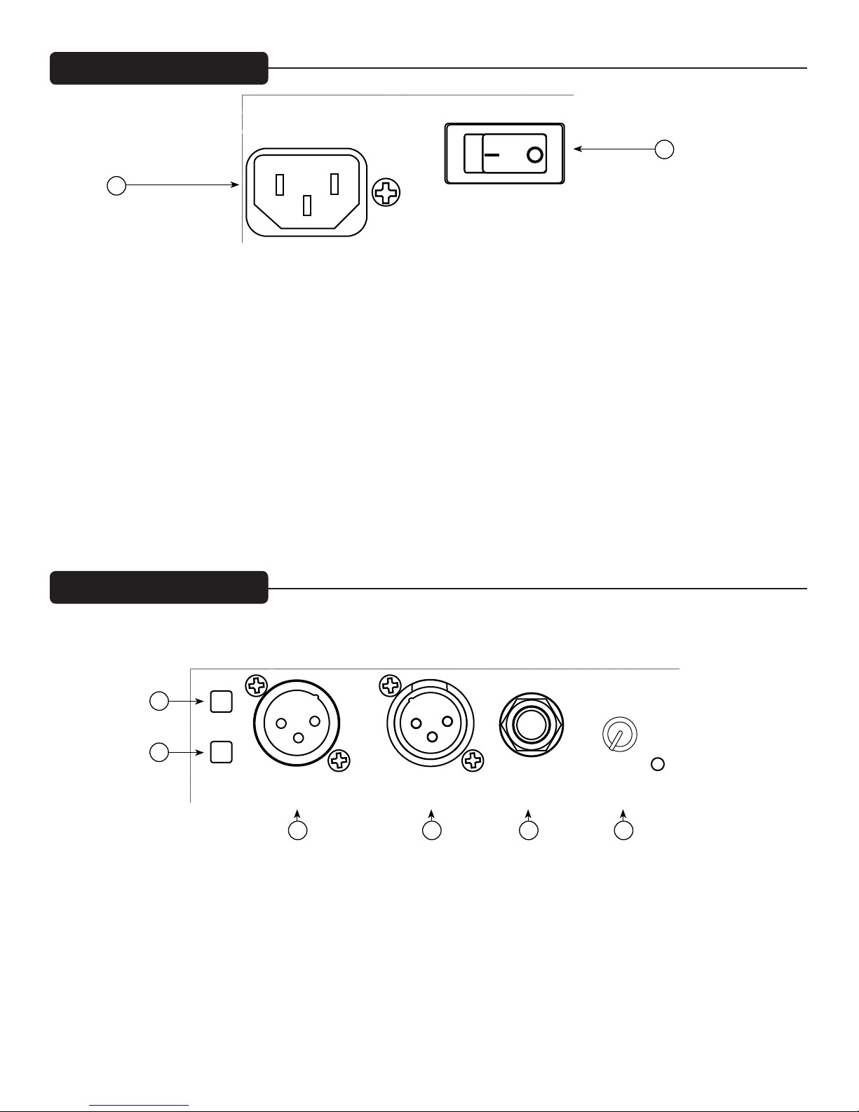
First, make sure the unit has AC power and is turned ON. Make sure the Power/Clip LED (9) is illuminated Green. If not, make
certain the ON/OFF switch (2) is in the ON position and check the IEC power cord connection (1) by ensuring it is fully engaged and
seated. Make certain the AC line cord is plugged into a working AC outlet.
Finally, check the internal fuse. (See the Rear Panel: Fuse section, for instructions.) Once assured your unit is getting AC power,
check that the 6505® SUB is getting a signal. Temporarily disconnect the cable running to its inputs and connect it to some other
device capable of reproducing the signal (i.e., a power amp and speaker). If this produces a signal, make sure that all Volume controls
being used have been turned up to a satisfactory level (one-third to halfway).
If the 6505® SUB has been subjected to direct sunlight or excessive heat, the built-in thermal protection may have been triggered. The
power/clip LED (9) will be illuminated RED if this is the case. If so, turn off the 6505® SUB and let it cool for a sufficient amount of
time.
If there is still no output, contact your authorized Peavey dealer or the Peavey International Service Center.
Hum or Buzz
If the 6505® SUB is producing a hum or buzz, this can be AC outlet related. Try plugging the 6505® SUB into a different AC outlet.
Sometimes, if a different circuit (breaker) is used for the guitar amp/combo and the 6505® SUB, it can cause hum problems.
Ensure that shielded cables have been used to route the signal to the 6505® SUBs inputs. If speaker cables with 1/4" plugs are used as
input cables instead of shielded cables, they will be prone to hum or buzz. Hum may be ground loop related. It will be helpful to lift
the shield ground on a balanced XLR cable at the 6505® SUB end only by using the ground lift switch (3). Check any input changes
carefully by first turning down the volume control, plugging and unplugging cables, or lifting the shield ground at the speaker end.
Check to make sure light dimmers are not on the same circuit as the 6505® SUB, the guitar amp/combo or any connected devices. If
light dimmers are used, then it may be necessary to turn them full ON or full OFF to eliminate or reduce hum. This is a typical AC
wiring/light dimmer interference problem, not a design flaw of the 6505® SUB.
The third wire (ground plug) on the AC plug should NEVER be removed or broken off.
Distorted or Fuzzy Sound When Sound Should be Clean
First, ensure the signal source is not clipping or being overdriven. Make sure the level control (8) on the 6505® SUB has not been set
too low or all the way up.
Check that the input plugs are fully seated in the input jacks (5) and (7) on the rear panel of the 6505® SUB. Ensure that a power amp
OUTPUT has not been plugged into the XLR input jack (5) of the 6505® SUB.
If an extension cord is being used to provide the AC power to the unit, ensure that it is of sufficient current capacity and that it is not
also being used to supply power to any other device.
Finally, realize that even though the 6505® SUB is a powerful and high output unit, it does ultimately have Limits. In this case, try
turning the levels down a little to see if that clears things up. If, after checking all the things listed to check and anything else you can
think of to check safely, and the system still exhibits problems, carefully note all conditions and check with your Peavey dealer for
advice.
Your 6505® SUB is a sturdy and durable product and will provide years of reliable use if properly cared for. Use common sense and
read the safety warnings to avoid hazardous operating conditions. The unit must be disconnected from the AC power source before
any work is done on it. Refer all servicing to qualified service personnel.
Sunlight/Heat
Avoid prolonged exposure to direct sunlight, as this may cause the unit to overheat and thermally shut off. Excessively hot operating
conditions can also cause a thermal shutdown. Do not store in extremely hot or cold conditions or extremely high humidity. Always
allow unit to come to room temperature before use.
Cleaning
Never clean the 6505® SUB while plugged in or turned ON! When the unit has been fully disconnected from AC power sources, use a
dry cloth or a plastic bristle brush to remove soil or other dirt. Never use strong solvents on the 6505® SUB, as they could damage the
cabinet. Do not allow ANY fluids to drip inside the 6505® SUB.

Specs
Architectural and Engineering Specifications
The powered loudspeaker system shall have a frequency range from 38 Hz to 120 Hz. The peak SPL with inaudible distortion shall
reach 119 dB with music as a source, when measured at a distance of 1 meter and driven to full output capacity. The system shall
utilize an 18” heavy-duty woofer.
The powered loudspeaker system shall have a medium impedance input connector consisting of a female XLR, and one 1/4” phone
jack for amplifier level signal input, located on the rear panel. A level control shall be provided.
The rear panel shall also provide a balanced XLR line-level output. A switch shall control whether the output is a full bandwidth
(thru) or a high-pass output with a corner frequency of 120 Hz, and a 4th order Linkwitz-Riley filter characteristic.
The system power amplifiers shall have an unfiltered frequency response of 10 Hz to 30 kHz which deviates no more than +0, -1 dB
up to rated power, a damping factor greater than 100 @ 1 kHz into 8 ohms, hum and noise better than 90 dB below rated power, and
THD and IMD of less than 0.1%. Each woofer amplifier shall be capable of 150 W RMS into an 8-ohm nominal load, providing a
total of 300 watts RMS, 600 watts total peak available power into the dual voice-coil woofer. Both amplifier channels shall incorporate
DDT™ compression.
The enclosure shall be constructed of 3/4” MDF, and covered in a black Tolex like material. A metal handgrip shall be provided on
each side of the enclosure.
A fabric-covered wooden frame grille shall be provided for woofer protection. The cabinet shall incorporate four sturdy rubber feet
for floor standing use, and four caster cups to hold a guitar amp/combo, on the top surface..
The outside dimensions shall be: 27” tall x 21.9” wide x 19.6” deep, and the weight shall be 87 lbs. Power requirements shall be:
100-Watts nominal (1/8 audio power), 100-120 VAC, 50/60 Hz Domestic and 220-240 VAC, 50/60 Hz (Export). The loudspeaker
system shall be called the Peavey 6505® SUB.
SPECS
Frequency Range, (-10 dB, half space) 38 Hz to 120 Hz
Frequency Response (+/- 3dB anechoic) 46 Hz to 90 Hz
Sensitivity (1w, 1m): 95 dB
Maximum SPL: 119 dB
122 dB peak
Transducer Complement: 18” Heavy-duty woofer with 3” voice coil, and 65 oz. magnet
Box Tuning Frequency: 46 Hz
Crossover Frequency: 120 Hz
Nominal Impedance (Z): 8 Ohms
Input Connections: Line level XLR jack input, speaker level 1/4" phone jack input
Note: DO NOT connect a bridged amplifier output to the speaker level input jack (7), or a single power amplifier channel that has the
polarity reversed. The jack sleeve is grounded!
Output Connections: Line-level XLR jack output, switchable to either Thru mode, or
High Pass Filter mode
Enclosure Materials & Finish: MDF covered in Black Tolex type material.
Dimensions (H x W x D): 22.00" x 29.88" x 19.19" / 559 mm x 759 mm x 487 mm
Net Weight: 87 lbs. (39.5 kg)
Specifications subject to change without notice.

Logo referenced in Directive 2002/96/EC Annex IV
(OJ(L)37/38,13.02.03 and defined in EN 50419: 2005
The bar is the symbol for marking of new waste and
is applied only to equipment manufactured after
13 August 2005
www.peavey.com
Warranty registration and information for U.S. customers available online at
www.peavey.com/warranty
or use the QR tag below
Features and specications subject to change without notice.
Peavey Electronics Corporation 5022 Hartley Peavey Drive Meridian, MS 39305 (601) 483-5365FAX (601) 486-1278
A
Table of contents
Other Peavey Subwoofer manuals

Peavey
Peavey TLS 2X User manual

Peavey
Peavey RBS 1 User manual

Peavey
Peavey SP 118 User manual

Peavey
Peavey TLS 115X User manual

Peavey
Peavey HDH-3 User manual

Peavey
Peavey Impulse 115P User manual

Peavey
Peavey SP 218 User manual

Peavey
Peavey SP 218X User manual

Peavey
Peavey PVX pSub User manual

Peavey
Peavey 118 Sub HC User manual

Peavey
Peavey Lo Max 15 User manual

Peavey
Peavey QW 118P User manual

Peavey
Peavey DJS 1500 User manual

Peavey
Peavey RX 22 User manual

Peavey
Peavey Impulse 1015 User manual

Peavey
Peavey 415 Sub User manual

Peavey
Peavey Impulse Impulse 500 User manual

Peavey
Peavey Low Rider 18 User manual

Peavey
Peavey Subcompact 18 User manual

Peavey
Peavey SP 118X User manual