©Copyright 2005 PECO, Inc. All Rights Reserved P/N 68841 3220-1479 Rev 0 Page 2
THERMOSTATOPERATION
APPLICATION NOTES
1.When nochangeover pipesensor isused, themain output
controlscooling andthe secondaryoutput controlsheating.
2.Thefanoutput,terminal 12,isenergizedwheneverthereis
ademandforheatingor cooling. This output can be
connected to a relay that can be used to provide fan cycling
to terminal 1.
3.Thechangeoverpipesensorshouldbe mountedonthe
main coil input for water system operation and in the main
ductsystemforforced airoperation.
4.The set pointandoperating mode willbe retained ona loss
ofpower.
5.Whenusing eitheraremoteprobeorpipesensor, runwiring
awayfromanyelectrical motorsorpowerwiring.
6. The auxiliary heat output supplies a 24 VAC signal with call
forheat. Thisoutputis shippedconfiguredforstaged heat.
7. The thermostat is shipped with all dip switches in the “ON”
(closed)position.
8.Thedamper outputis ONwhen modeisAUTO,HEATor
COOL, damper is OFF in set back.
CONFIGURATION
CIRCUIT BOARD JUMPER CONFIGURATION
Jumper
Designation Closed
ON* Open
OFF
JP1
JP2
JP3
JP4
JP5
LocalSensing
2PipeSystem
FactoryUseOnly
0-10VOC
Main Output
0-10VOC
SecondaryOutput
Remote Sensing
4PipeSystem
4-20mA
Main Output
4-20mA
SecondaryOutput
* On is with the dip switch handle to the right-see diagram below
DIP SWITCH CONFIGURATION
Switch
Designation Closed
On* Open
Off
1
2
3
4
5
6
Not Used Not Used
Not Used
Staged Heat
3°F Diff. (Term. 13) Aux. Heat No
Diff. (Term. 13)
FDisplay CDisplay
Main & Sec. Outputs
0-10 VOC (Term. 10 & 11)
requiresJP4 &JP5
Main & Sec. Outputs
4-20mA(Term. 10 & 11)
RemoveJP4 & JP5
Operating Position
Setback=90°F & 50°F Setback= 85°F & 60°F
Thesethermostatsaredesignedtocontrol0-10 VDC/4-0mA
valves. Theseunits mayincludea fanswitch withone or
morefanspeedselections.
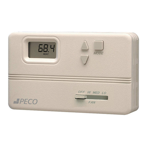
MODEBUTTONOPERATION
OFF All thermostat outputs are off, fan is still operational if
connected to a manual fan switch.
AUTO Thethermostat automaticallyselectsheating or
coolingmodedependingupontherelationshipofthe
setpoint andtheroomtemperature. Theappropriate
HEATor COOLindicator isenabled inaddition to
AUTO. A 3°Fdead bandisprovidedtoprevent
shortcyclingbetween heatingandcoolingmodes.
Afterchangeover,thecontrol pointsautomatically
shift so that the heating off point equals the set
pointtemperatureorthe coolingoffpointequalsthe
setpointtemperature.
COOL Thethermostatoperates asacooling only
thermostat. Theheatingoutputsare disabled.
HEAT The thermostatoperatesasaheating only
thermostat. Thecoolingoutputsaredisabled.
FANSPEEDSWITCHOPERATION
Fanspeedis determinedbymanual selectionfrom
fanswitch OFFto HIGH,MEDIUM and/orLOW. In
the OFF position all outputs are off and the display is
blank.
UP/DOWNARROW OPERATION
A first touch of either arrow will display the setpoint
(a single set point is employed for both heating and
cooling). Continuedpressure oneither arrowwill
scroll the setpoint to new values. After three
consecutiveseconds on eitherarrow,the selected
setpointbecomes effective andthe displayofthe
roomtemperate resumes.
Item# Function Range Default
1 Zone TempOffset -5.1Fto 5.1F 0F
2 Valve Stroke Time 30 sec. To 5 min. 120 sec.
3 Fan Delay to OFF 2to10 Minutes 120 Sec.
4 Compressor Minimum
Off Time 30 Sec. To 10 min. 120 Sec.
5 PurgeCycle 0= TimeBased
1= Temperature Based 1
Service Menu:
Access: Press UP and DOWN arrows for 5 seconds.
Menu Selection: Select 1 to 5 by pressing the mode button
or by pressing the UP and DOWN arrows simultaneously.
Adjust Value: Use UP or DOWN arrow.
