manuals.online logo
Brands
  1. Home
  2. •
  3. Brands
  4. •
  5. Peco
  6. •
  7. Thermostat
  8. •
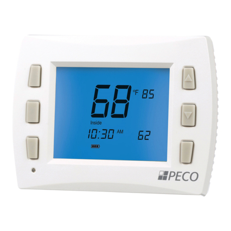
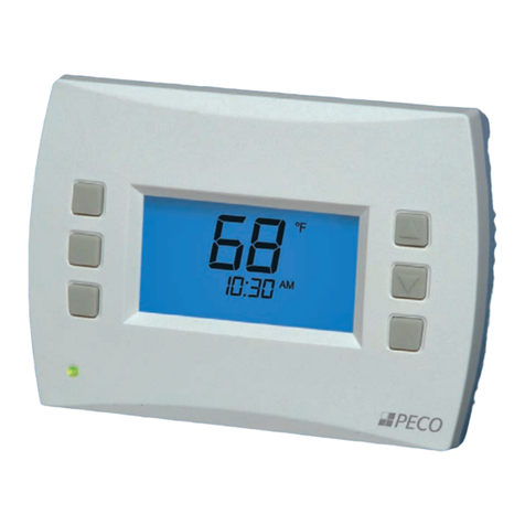
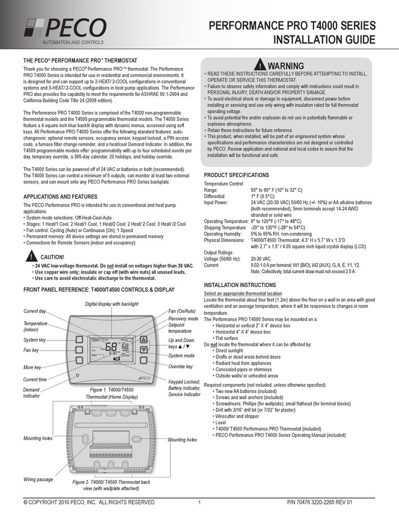
  9. Peco Performance pro T4000 series User manual

Peco Performance pro T4000 series User manual

Other manuals for Performance pro T4000 series

3

This manual suits for next models

1

Other Peco Thermostat manuals

Peco T2500-01 WavePRO User manual

Peco

Peco T2500-01 WavePRO User manual

Peco TA170 User manual

Peco

Peco TA170 User manual

Peco TH170 User manual

Peco

Peco TH170 User manual

Peco T158 User manual

Peco

Peco T158 User manual

Peco TB158 User manual

Peco

Peco TB158 User manual

Peco Performance PRO TW180 User manual

Peco

Peco Performance PRO TW180 User manual

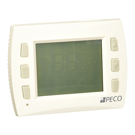
Peco Performance pro T4000 series User manual

Peco

Peco Performance pro T4000 series User manual

Peco TA180 User manual

Peco

Peco TA180 User manual

Peco T180 User manual

Peco

Peco T180 User manual

Peco T190 User manual

Peco

Peco T190 User manual

Peco WavePRO T2500 User manual

Peco

Peco WavePRO T2500 User manual

Peco T8000 series User manual

Peco

Peco T8000 series User manual

Peco TF115P-002 User manual

Peco

Peco TF115P-002 User manual

Peco Peco TW206 User manual

Peco

Peco Peco TW206 User manual

Peco TA155 User manual

Peco

Peco TA155 User manual

Peco WavePRO K2500-001 User manual

Peco

Peco WavePRO K2500-001 User manual

Peco Peco RW205 User manual

Peco

Peco Peco RW205 User manual

Peco TW180 User manual

Peco

Peco TW180 User manual

Peco TA167-006 User manual

Peco

Peco TA167-006 User manual

Peco T168 User manual

Peco

Peco T168 User manual

Peco TB167 User guide

Peco

Peco TB167 User guide

Peco Performance pro T12000 User manual

Peco

Peco Performance pro T12000 User manual

Peco TA170-001 Installation guide

Peco

Peco TA170-001 Installation guide

Peco T8000 series User manual

Peco

Peco T8000 series User manual

Popular Thermostat manuals by other brands

Full Gauge TIC-17C product manual

Full Gauge

Full Gauge TIC-17C product manual

Imit Chronomix S manual

Imit

Imit Chronomix S manual

ChiliTec ST-35 ana instruction manual

ChiliTec

ChiliTec ST-35 ana instruction manual

Salus VS05 Installer's/user's manual

Salus

Salus VS05 Installer's/user's manual

Azel D-500 user guide

Azel

Azel D-500 user guide

Honeywell Chronotherm III owner's manual

Honeywell

Honeywell Chronotherm III owner's manual

Charmeg MP-R user manual

Charmeg

Charmeg MP-R user manual

dixell WING XW40LS Installing and operating instructions

dixell

dixell WING XW40LS Installing and operating instructions

Network Thermostat NetX X7C-WIFI Installation and programming manual

Network Thermostat

Network Thermostat NetX X7C-WIFI Installation and programming manual

Radio Thermostat CT80 Operation guide

Radio Thermostat

Radio Thermostat CT80 Operation guide

HAI Omnistat RC-120 installation manual

HAI

HAI Omnistat RC-120 installation manual

Lennox iComfort E30 Installation and setup guide

Lennox

Lennox iComfort E30 Installation and setup guide

Lux Products PSD011Ba Installation and operating instructions

Lux Products

Lux Products PSD011Ba Installation and operating instructions

Computherm Q20 operating instructions

Computherm

Computherm Q20 operating instructions

Heatmiser neoStat user manual

Heatmiser

Heatmiser neoStat user manual

Mars HEAT CONTROLLER IR Wireless Thermostat user manual

Mars

Mars HEAT CONTROLLER IR Wireless Thermostat user manual

LUX LP0511D user manual

LUX

LUX LP0511D user manual

Saswell SAS920XWHB-7-S-RF User manual and warranty card

Saswell

Saswell SAS920XWHB-7-S-RF User manual and warranty card

manuals.online logo
manuals.online logoBrands
  • About & Mission
  • Contact us
  • Privacy Policy
  • Terms and Conditions

Copyright 2025 Manuals.Online. All Rights Reserved.

© COPYRIGHT 2014 PECO ASTRONICS. ALL RIGHTS RESERVED. P/N 70930 3220-2322 REV 00



Next.
Next

Next
Next

NextMo

Days
Done



Next  Go Back


Done





 
 
 
 
 
 
 



WARNING: DISCONNECT POWER BEFORE BEGINNING INSTALLATION.
• CAUTION: Use copper wire only. Insulate or wire-nut all unused leads.
• Use care to avoid electrostatic discharge to thermostat
• CAUTION: Do not connect unused wires together
• ALL ELECTRICAL LOADS MUST BE CONNECTED TO TERMINAL C
(24 VAC).

Conventional Heat Pump
C24 VAC, Unswitched side C24 VAC, Unswitched side
W1 Stage 1 Heat B/O Reversing Valve
W2 Stage 2 Heat AUX Auxiliary Heat (Stage 3 Heat)
GFAN GFAN
A A
E E
Y1 Stage 1 Cool Y1 Compressor Stage 1, Heat/Cool 1
Y2 Stage 2 Cool (or Dehumidify) Y2 Compressor Stage 2 Heat/Cool 2
(or Dehumidify)
RH 24 VAC Power for heating,
switched side RH 24 VAC Power for heating,
switched side
RC 24 VAC Power for cooling,
switched side RC 24 VAC Power for cooling,
switched side
SC Sensor Common SC Sensor Common
S1 Indoor Remote Sensor S1 Indoor Remote Sensor
S2 Occupancy Sensor S2 Occupancy Sensor
▲





QUICK START GUIDE
PERFORMANCE PRO T4000
AN ASTRONICS COMPANY
© COPYRIGHT 2014 PECO ASTRONICS. ALL RIGHTS RESERVED. P/N 70930 3220-2322 REV 00

MENU FEATURE OPTIONS STD. DEFAULT DESCRIPTION / COMMENTS
100 Schedule Format 0-3 1 Select the schedule format on the T4000 Series. (Menu not available on non-programmable
thermostats.)
0 = nonprogrammable
1 = programmable
2 = 5-1-1 schedule
3 = 5-2 schedule
101 Daylight-Saving
Time
0,1 0 Select daylight-saving time as it follows standard format in U.S.: It begins second Sunday of
March at 2:00 AM and ends on the rst Sunday of November at 2:00 AM.
0 = Disabled
1 = Enabled (2007 U.S. Format)
110 System Type 1-13 1 Select the appropriate system conguration (determines available Service Menus).
1 = 1 Heat/1 Cool conventional
2 = 1 Heat/1 Cool heat pump
3 = Heat only without fan (2-wire systems)
4 = Heat only with fan
5 = Cool only
6 = 2 Heat/1 Cool heat pump (with auxiliary heat) and Emergency (Em) heat
7 = 2 Heat/2 Cool multistage conventional
8 = 2 Heat/ 1 Cool multistage conventional
9 = 1 Heat/ 2 Cool multistage conventional
10 = 2 Heat/ 2 Cool heat pump (no auxiliary heat)
11= 3 Heat/ 2 Cool heat pump (with auxiliary heat) and Emergency (Em) heat
120 Fan Control
(heating)
0,1 0 0 = Fossil Fuel: Gas/Oil/Propane heat (equipment controls heating fan)
1 = Electric Furnace (thermostat controls heating fan)
130 O/B Reversing
valve
0,1 0 When 0, output is active for cooling. When 1, output is active for heating.
0 = (O) Active with cooling
1 = (B) Active with heating
140 Auxiliary Heat 0,1 0 0 = Electric backup heat
1 = Fossil fuel backup heat
150 Backlight 0,1 0 0 = Backlight temporarily on
1 = Backlight always on (low intensity, 24V only)
170 Remote Sensor 0-1 0 Select sensor if used. Contact PECO for information on the T4000 Series Indoor Remote Zone
Sensor.
0 = No Remote Sensors
1 = Indoor Sensor Only
240 Number of Program
Periods
2; 4 events 4 2 = 2 events per day (Selections OCC1 and UnOcc1)
4 = 4 events per day (Selections Occ1-UnOcc1-Occ2- UnOcc2)
250 Clock format 12 or 24 Hours 12 12 = 12-hour clock mode
24 = 24-hour clock mode
260 Temperature Format
(°F or °C)
0,1 1 0 = Celsius
1 = Fahrenheit
270 Fan Off Delay Heat 0-99 Seconds 0 Select the amount of time (in seconds) that the fan will run after the thermostat heat outputs are
turned off.
280 Fan Off Delay Cool 0-99 Seconds 0 Select the amount of time (in seconds) that the fan will run after the thermostat cool outputs are
turned off.
290 Range Low 50-90 °F or
10-32°C
50°F (10°C) Choose the lowest selectable temperature setpoint value.
300 Range High 50-90 °F or
10-32°C
90°F (32°C) Choose the highest selectable temperature setpoint value.
310 Setback Low Off; 50-82°F or
11-27°C
55°F (13°C) Select the heat setpoint for setback mode.
0 = Off
50-82°F (11-27°C)
320 Setback High Off; 58-90°F or
11-32°C
90°F (32°C) Select the cool setpoint for setback mode.
0 = Off
58-90°F (11-32°C)
330 Zone Temp Offset +/-9°F or +/-
4.5°C
0°F (18 °C) Adjusts the displayed value; may differ from actual zone temperature.
340 Keypad Lockout 0-3 0 Restricts access to certain features of device; Service Menu still available if enabled.
0 = No key pad lockout (Default)
1 = Disables Schedule and System keys
2 = Disables Schedule, System, and Fan keys
3 = Disables all keys


© COPYRIGHT 2014 PECO ASTRONICS. ALL RIGHTS RESERVED. P/N 70930 3220-2322 REV 00

MENU FEATURE OPTIONS STD. DEFAULT DESCRIPTION / COMMENTS
341 

  Applies a 3 digit access code to enter Service Menu 342
0 = Disable,
1 = Enable
342 Set PIN Access
Code
000-999 000 Choose a 3-digit code.
350 Fan Mode
Enable
1-3 3 1 = ON: Fan is turned on regardless of demand.
2 = Auto: Fan is turned on according to heating or cooling demand.
3 = ON or Auto: Allows occupant to select either 1 or 2 above.
360 System Mode
Enable
0-3 1 Allows ability to determine which system modes the occupant can select.
0 = OFF, Auto (0 is NOT valid for following congurations: Heat Only; Cool Only.)
1 = OFF, Heat, Cool, Auto
2 = OFF, Heat, Cool
3 = Heat, Cool, Auto
380 Minimum Deadband
Adjustment
3-10°F, 1.5-5°C 3°F Select a changeover deadband value to prevent short cycling between heating and cooling
modes.
The value is adjustable to meet various HVAC system requirements.
390 Pre-Occupancy
Purge
0-3 hours 0 hours Select to energize fan for selected number of hours (0-3) prior to all occupied events.
395 Maximum Override
Time Limit
0=Time until next
event; or
1-4 hours
3 Restricts the duration that a temporary hold can be set. The temporary hold is limited by the
maximum amount of time as dened in this Service Menu.
0 = Remainder of time until the next scheduled event.
1 = 1 Hour
2 = 2 Hours
3 = 3 Hours
4 = 4 Hours
400 Cycles Per Hour
(CPH)
Cooling Stage 1
0-6 CPH 0 CPH Denes the number of cycles per hour for cooling (Stage 1). Select 0 to enable ON-OFF
control for Stage 1 cooling.
410 Cycles Per Hour
(CPH)
Cooling Stage 2
0-6 CPH 0 CPH Denes the number of cycles per hour for cooling (Stage 2). Select 0 to enable ON-OFF
control for Stage 2 cooling.
420 Cycles Per Hour
(CPH)
Heating Stage 1
0-12 CPH 0 CPH Denes the number of cycles per hour for heating (Stage 1). Select 0 to enable ON-OFF
control for Stage 1 heating.
430 Cycles Per Hour
(CPH)
Heating Stage 2
0-12 CPH 0 CPH Denes the number of cycles per hour for heating (Stage 2). Select 0 to enable ON-OFF
control for Stage 2 heating.
450 Cycles Per Hour
Heating Stage 3
0-12 CPH 0 CPH Denes the number of cycles per hour for heating. Select 0 to enable ON-OFF control for
Heating Stage 3.
460 Heat Recovery Rate 0-18°F/Hr
0-10°C/Hr
0°F/Hr Denes the rate at which the device achieves the heat comfort setpoint. Select 0 to disable
ramp recovery.
470 Cool Recovery Rate 0-18°F/Hr
0-10°C/Hr
0°F/Hr Denes the rate at which the device achieves the cool comfort setpoint. Select 0 to disable
ramp recovery.
480 Minimum Off Time 1-10 minutes 4 minutes Sets the minimum off time for both the heat and cool output.
490 Humidity Control
Enable
(Select models only)
Selects how humidity will be controlled. When dehumidify control is enabled, the Y2
terminal becomes dehumidify.
0 = Disabled
1 = Dehumidify Control
500 Programmable/
Intermittent Fan
0-2 0 0 = Disable
1 = Programmable Fan: Fan operates continuously in occupied periods or with demand in
unoccupied periods.
2 = Intermittent Fan: Fan operates based on the on and off times set in menus 501 and
502.
501 Intermittent Fan On
Time
1-60 minutes 5 minutes Denes the on time for the Intermittent Fan.
502 Intermittent Fan Off
Time
0-60 minutes 25 minutes Denes the off time for the Intermittent Fan. Select 0 for continuous fan.
© COPYRIGHT 2014 PECO ASTRONICS. ALL RIGHTS RESERVED. P/N 70930 3220-2322 REV 00

MENU FEATURE OPTIONS STD. DEFAULT DESCRIPTION / COMMENTS
520 Default Display
Icons
0-4 0 Select icons that will be displayed in the Default Display screen.
0 = Time, Temp, Setpoint (SP)
1 = Time, Temp
2 = Time
3 = Temp
4 = None
530 Revision — — Displays  rmware revision information (for technician); not adjustable.
540 Factory Default
Reset
0,1 0 Select 1 (enable) to restore factory default settings for thermostat. Select 0 to disable.
0 = Disable
1 = Enable
Note: Press “Done” key to complete process.
600 System Test Main
Output (Cool)
0-2 0Select option to activate fan output for 10 minutes; select 0, Done or a different Service Menu to disable.
0 = Disable (Default)
1= Cool Stage 1
2 = Cool Stage 2
610 System Test Main
Output (Heat)
0-3 0 Select an option to activate the fan output for 10 minutes; select 0, Done or a different Service Menu to
disable. Note: Outputs will be activated based upon the system con guration.
0 = Disable (Default)
1 = Heat Stage 1
2 = Heat Stage 2
3 = Heat Stage 3
620 

  Select 0 or 1 to activate the fan output for 10 minutes; select 0, Done or a different Service Menu to
disable. Note: For Service Menus 610 and 620, outputs activated based upon the system con guration
0 = Disable Fan Output
1 = Enable Fan Output Note: Outputs will be activated based upon the system con guration.