Automation & Controls
Division of PECO, Inc.
Portland, OR 97282
800-874-8547 or 503-233-6401
www.pecomanufacturing.com
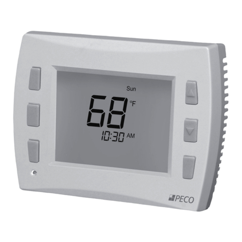
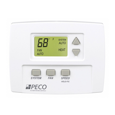
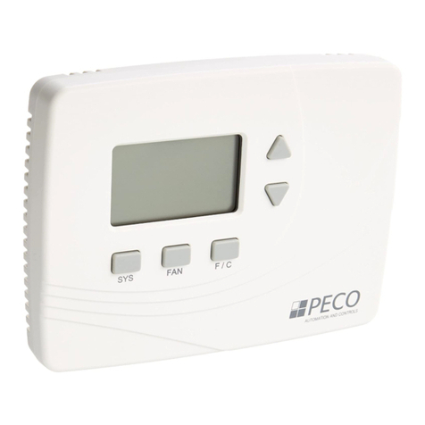
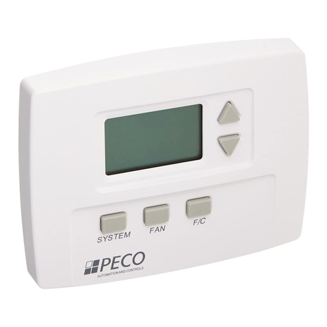
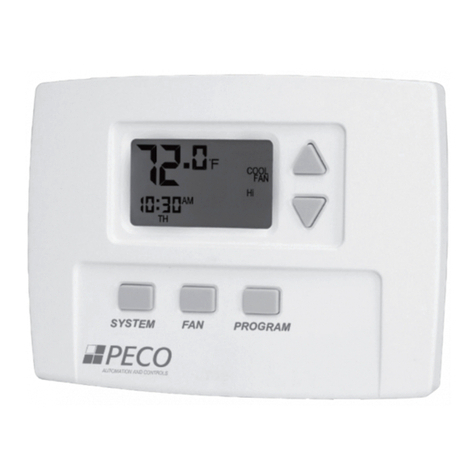
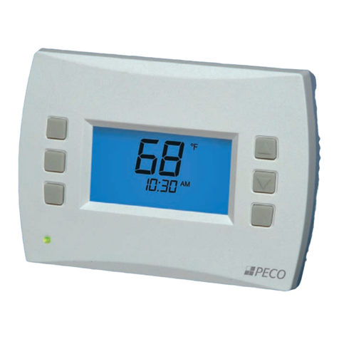
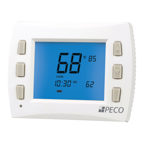
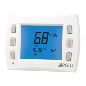
Performance PRO™ T8000 Series
T8000
Series Gas
Electric
Oil Heat Pump
Technical Data
Specifications
Temperature Control Range 50° to 90° F (10° to 32° C)
Operating Temperature Range 0° to 120° F (-18° to 49° C)
Storage Temperature Range -20° to 130° F (-29° to 55° C)
Electrical Input Frequency 50/60 Hz +/- 10%
Input Power 24 VAC (20-30 VAC) and/or 2 AA alkaline
batteries (Installing batteries recommended)
Output Terminal W - Heating 20-30 VAC 0.02-1.0 A
Output Terminal Y - Cooling 20-30 VAC 0.02-1.0 A
Output Terminal G - Fan 20-30 VAC 0.02-0.6 A
Output Terminal A - Economizer 20-30 VAC 0.02-1.0 A
Dehumidifi cation Sensor 0 - 100% RH
Dehumidifi cation Range 25% - 99% RH
Termination Connections Wallplate w/ terminal blocks
Memory Card SD (Secure Digital)
Specifications
Total load not to exceed 2.5 A
Mounting Direct mount; 2" x 4" horizontal
or vertical, or 4" x 4"
LCD Viewable Size 8 inch2 - 2.5" W x 3.2" H
51.8 cm2 - 6.4 cm W x 8.1 cm H
Physical Dimensions 5.7”W x 4.3"H x 1.3"D
Dimensions
Model Part No. Description
T8532-IAQ 70337 Performance PRO 3 Heat/2
Cool staging, programmable w/
Humidifi cation/Dehumidifi cation
control
T8532-001 69922 Performance PRO 3 Heat / 2
Cool staging, programmable.
T8522-001 70333 Performance PRO 2 Heat
/2 Cool staging, programmable.
70271 70271 Wallplate. Performance PRO
common wallplate: applicable to
all series models.
69308 69308 Indoor remote sensor
70327 70327 Outdoor remote sensor
SB200-001 68375 Occupancy sensor - time based
SK200-001 68381 Occupancy sensor - guest room
CONVENTIONAL
HEAT PUMP B/O AUX
C W1 W2 G A E Y1 Y2 RH RC SC S1 S2 S3
CONVENTIONAL
HEAT PUMP B/O AUX
C W1 W2 G A E Y1 Y2 RH RC SC S1 S2 S3
Performance PRO Wallplate
& Terminal Connections
DS-T8000 - 9/10 © PECO, Inc. 2010
Models & Accessories
Terminals
Conventional Heat Pump
C
W2
G
E
Unswitched side 24 VAC
Stage 2 Heat
Fan Relay
Stage 1 Heat
Stage 3 Heat
Sensor Common
W1
A
SC
Unswitched side 24 VAC
RC
Power to Cooling switched side Power to Cooling switched side
Y2
Stage 2 Cool or Dehumidify Compressor Stage 2
Heat / Cool or Dehumidify
Y1
Stage 1 Cool
Compressor Stage 1
Heat / Cool
Indoor remote sensor S1 Indoor remote sensor
Setback input S2 Setback input
Emergency
Sensor Common
RH
Power to Heating switched side Power to Heating switched side
Fan Relay
Outside remote sensor S3 Outside remote sensor
Economizer, Damper Control
or Humidify
B/O
AUX
Reversing valve
Auxiliary (Stage 3 Heat)
Economizer, Damper Control
or Humidify
4.3”
(10.9 cm)
5.7”
(14.5 cm)
1.3”
(3.3 cm)
Memory
Card
T8000 Thermostat
RoHS Compliant
