manuals.online logo
Brands
  1. Home
  2. •
  3. Brands
  4. •
  5. Peco
  6. •
  7. Thermostat
  8. •
  9. Peco TF115P-003 User manual

Peco TF115P-003 User manual

© COPYRIGHT 2019 PECO, INC. ALL RIGHTS RESERVED. P/N 73433 REV 00
1
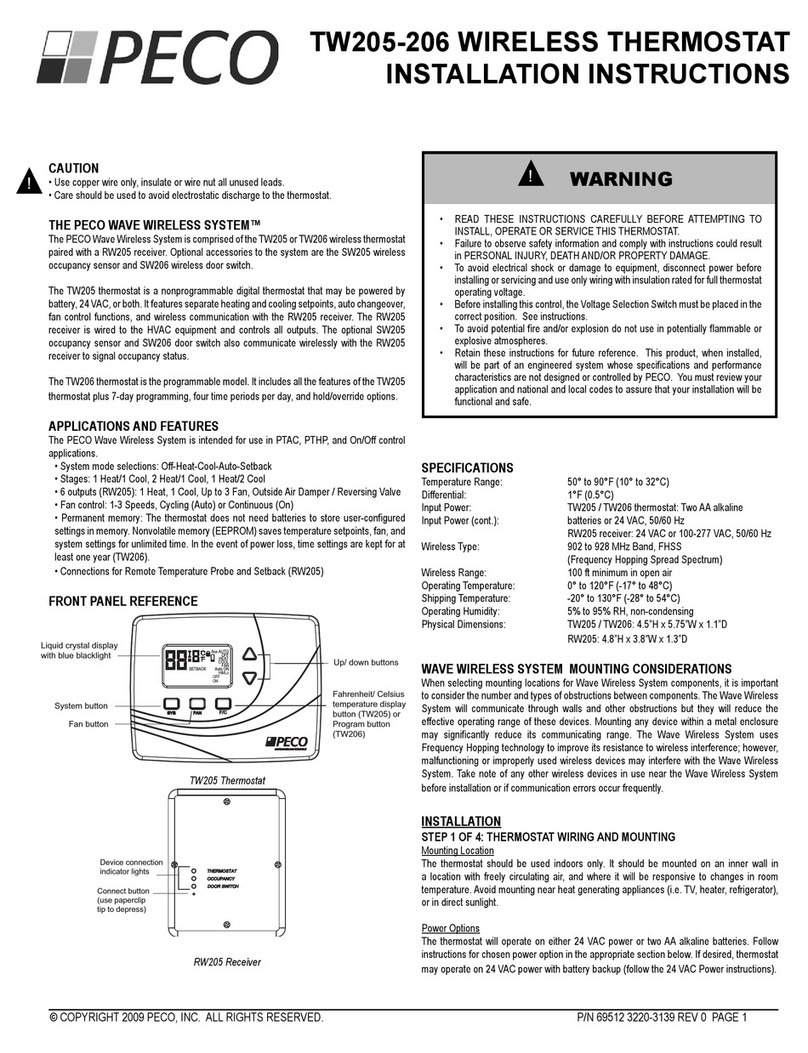
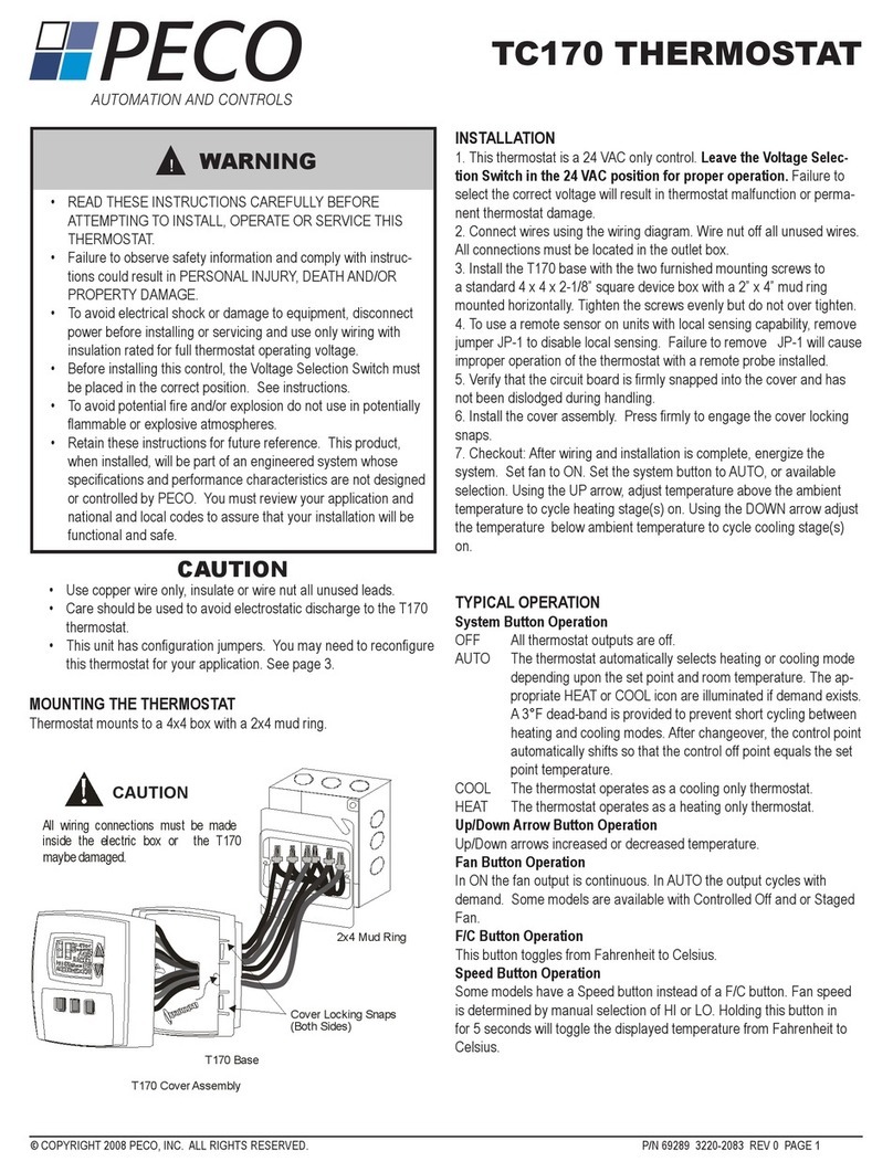
TF115P-003 THERMOSTAT
INSTALLATION GUIDE
TF115P-003 RAINTIGHT THERMOSTAT
The PECO®TF115F-003 is a robust commercial thermostat—fully assembled, and ready
to use — for plug-in temperature control of ventilation in greenhouses, warehouses and
industrial facilities. The rugged enclosure can be used for cooling or heating in indoor or
outdoor applications. Note: For cooling applications, see Wiring Diagram on page 2.
The PECO®TF115F-003 control, which is housed in the raintight gray plastic enclosure,
uses a stainless steel coil as a temperature-sensing bulb.
Maximum sensing element withstand temperature is 145°F (62°C). Maximum temperature
for the plastic enclosure is 140°F (60°C).
INSTALLATION INSTRUCTIONS
Locate the thermostat about four feet (1.2 m) above the oor on a wall in an area with
good ventilation and an average temperature, where it will be responsive to changes in
room temperature. The unit is to be assembled with cover, gasket, and four (4) screws
installed and fully tightened (see Fig. 1). The TF115P-003 enclosure may be mounted
onto a wall or panel surface with #8 or #10 screws.
• With the plug-in inserted to 120 VAC outlet, a heater may be plugged into the series plug
(see Fig. 2) to provide temperature-related operation.
• Power cord is attached to internal leads; default wiring is set for heating.
• Adjustable temperature range is 40° to 110° F (4° to 43° C)
• Temperature Dial: One dial division equals 2°F (1.1° C) (See Fig. 1)
• Cord seal must remain tightened around power cord to maintain rain-tight seal; if removed,
the locking nut must be held stationary while gland nut is fully tightened (see Fig 1, 2)
CAUTION! USE 120 VAC ONLY!
TF115P-003 FRONT PANEL AND SIDE REFERENCE
PRODUCT SPECIFICATIONS
VAC INDUCTIVE RESISTIVE
AMPS
PILOT
DUTY
FLA LRA
13 125 VA120 4.4 26.4
Temperature Control Range: 40° to 110° F (4° to 43° C)
Differential: 3° F (1.7°C)
Maximum Ambient Temperature: 140°F (60°C)
Dimensions: 2.80”(L) X 2.5” (W) X 7” (H) inches
Line cord: 6 feet, 7-wire, double insulated, 16 AWG,
U.L. Listed, Plug: 3-pole male/female,
120 VAC plug style, American (grounded)
Weight: 0.88 lbs
OPERATION AND CHECKOUT
Allow one hour or necessary amount of time for the thermostat and system to stabilize for
normal operation. This thermostat is factory calibrated and requires no correction on site.
By default, the TF115P-003 thermostat is wired for heating operation.
To Check Operation:
1. Set Temperature Dial to desired temperature setpoint.
2. Plug the controlled device (e.g., fan) into the series plug (female side of TF115P plug).
3. Plug the TF115P power cord into the wall outlet. Note: Outlet must be 120 VAC.
4. To start operation, rotate Temperature Dial. Wait for the unit to turn on.
Note: For units that are wired for Heating operation (default) rotate the Dial at least
ve (5) degrees above the current ambient temperature. For units that are rewired for
Cooling operation, rotate the Dial at least ve (5) degrees below the current ambient
temperature.
5. Return Temperature Dial to the desired temperature setpoint. (The TF115P will
automatically control to desired temperature).
▲
!
100
50
35
LO
10
40
5
40
C
110
F
25
60
20
15
70
30
90
80
CAUTION
PRECAUCION / ATTENTION
DISCONNECT POWER BEFORE REMOVING COVER.
DEBRANCHER LE COURANT AVANT
DE RETIRER LE COUVERCLE.
DESCONECTE LA ENERGIA ANTES
DE REMOVER LA CUBIERTA.
Sensing bulb
Temperature
Dial
Temperature
Dial
Junction
Box
Cover
Junction
Box
Cover
Cord
Seal
(Locking nut
and gland
nut)
Cord
Seal
(Locking nut
and gland
nut)
Power
Cord
Figure 1. TF115P-003. Frontal view Figure 2. TF115P-003. Side view
Power
Cord
Series
Knockout
(side)
Sensing bulb
WARNING
• READ THESE INSTRUCTIONS CAREFULLY BEFORE ATTEMPTING TO INSTALL,
OPERATE OR SERVICE THIS THERMOSTAT. Failure to observe safety information
and comply with instructions could result in PERSONAL INJURY, DEATH AND/OR
PROPERTY DAMAGE.
• Retain these instructions for future reference.
• To prevent overheating or re, use this control as an operating or regulating
thermostat. ALWAYS USE A BACKUP CONTROL OR ALARM if a control failure could
cause the controlled appliance to overheat or could cause a re.
• Do not install, use or operate if product appears damaged, the enclosure is cracked or
broken or if the sensor has been bent, crimped or is dirty.
• To avoid potential re and/or explosion, do not use in potentially ammable or
explosive atmospheres.
• IMPORTANT: Do not impact, dent or use the sensor for support. This will cause
calibration and/or thermostat failure.
▲
!
© COPYRIGHT 2019 PECO, INC. ALL RIGHTS RESERVED. P/N 73433 REV 00
2
WIRING DIAGRAMS
HEATING (DEFAULT ) OPERATION
By default, the TF115P-003 is wired as a heating control (see Fig. 3).
COOLING OPERATION
• WARNING: Disconnect power before changing wiring.
To change the operation from a heating control to a cooling control, proceed
with the following steps.
1. Remove TF115P plug from the outlet to disconnect power.
2. Unscrew four screws and remove the junction box cover (see Fig. 4).
3. Disconnect the red and white wires by removing the wirenut.
4. Connect the blue and white wires together with the wirenut (see Fig. 5).
5. Twist the wirenut on the red wire only.
6. Re-install the junction box cover and tighten four screws.
LIMITED WARRANTY
1. WARRANTY COVERAGE. PECO Automation and Controls warrants to the original
user of its products that the products will, at the date of initial purchase, meet the
applicable specication for such products and will be free from any defects in materials or
manufacture under normal use for 18 months after date of manufacture.
2. DISCLAIMER OF WARRANTY OF PRODUCT SUITABILITY. PECO Automation and
Controls makes no warranty to the purchaser or any third party that its products are
suitable for a particular application or design. Many states and localities have differing
codes or regulations governing the installation and/or use of PECO Automation and
Controls’ products. PECO Automation and Controls cannot guarantee compliance with
such regulations; purchaser is solely responsible for safe and correct installation and use
of the product and for compliance with applicable codes and regulations.
3. EXCLUSION OF IMPLIED WARRANTIES. This warranty is the only warranty
applicable to this product and excludes all other warranties, including any WARRANTY
OF MERCHANTABILITY, any warranty of tness for a particular purpose, and any implied
warranties otherwise arising from course of dealing or usage of trade, except where the
product purchased is subject to consumer product warranty laws, in which case ANY
APPLICABLE IMPLIED WARRANTIES ARE LIMITED TO 18 MONTHS, or such shorter
period as permitted or required under applicable law. Some States do not allow limitations
on how long an implied warranty lasts, so the above limitations may not apply to you.
4. REMEDIES FOR NONCONFORMITY. If the product purchased does not conform to
the applicable warranty, PECO Automation and Controls will provide, at its option and in
accordance with the procedures in the following section, one of the following remedies:
(1) repair of the nonconforming product, (2) replacement with a conforming product, (3)
refund of the original purchase price. THESE REMEDIES SHALL BE THE EXCLUSIVE
AND SOLE REMEDY for any breach of warranty.
5. TO OBTAIN WARRANTY SERVICE. For any product believed to be defective within
the limited warranty period, rst write or call dealer from whom product was purchased.
Dealer will give additional directions. If unable to resolve satisfactorily, write to PECO
Automation and Controls at the address below, giving dealer’s name, address, date and
number of dealer’s invoice, and describe the nature of the defect.
6. LIMITATION OF LIABILITY. PECO Automation and Controls WILL NOT BE LIABLE
FOR ANY INCIDENTAL, SPECIAL, INDIRECT OR CONSEQUENTIAL DAMAGES
resulting from any defect in the product purchased. Some States do not allow the
exclusion or limitation of incidental or consequential damages, so the above limitation
or exclusion may not apply to you. This warranty gives you specic legal rights, and you
may also have other rights which vary from State to State.
Manufactured by PECO, Inc.
11241 SE Highway 212
Clackamas, OR 97015 USA
(PECO Automation and Controls is a division of PECO, Inc.)
Note: Even though this thermostat is sealed, water or dust may enter through improperly
sealed wiring. The cover must be tightened securely to compress the gasket and provide
a watertight seal. Use only screws provided. Do not over-tighten.
PECO is a registered trademark of PECO, Inc. All other trademarks, and/or registered trademarks, are the property of their respective owners.
GRND
STAT
WHITE
BLACK
GREEN GREEN
BLACK
BLUE
RED
THERMOSTAT
ENCLOSURE
HEATING
GROUNDED
SERIES PLUG
▲
!
Figure 3.
TF115P-003.
Wiring for
HEATING.
Figure 4.
TF115P-003
Junction Box
removed.
GRND
STAT
WHITE
BLACK
GREEN GREEN
BLACK
BLUE
RED
THERMOSTAT
ENCLOSURE
COOLING
GROUNDED
SERIES PLUG
Figure 5.
TF115P-003.
Wiring for
COOLING.
TO ENSURE WATER TIGHTNESS, THE GASKET MUST BE RE-INSTALLED UNDER THE
JUNCTION BOX COVER.
WARNING
▲
!

Other Peco Thermostat manuals

Peco TC170 User manual

Peco

Peco TC170 User manual

Peco TA155 User manual

Peco

Peco TA155 User manual

Peco TA170-001 Installation guide

Peco

Peco TA170-001 Installation guide

Peco TA155-046 Installation guide

Peco

Peco TA155-046 Installation guide

Peco PERFORMANCE PRO MULTI-FAN User manual

Peco

Peco PERFORMANCE PRO MULTI-FAN User manual

Peco TB158 User manual

Peco

Peco TB158 User manual

Peco Perfomance Pro School T4900 User manual

Peco

Peco Perfomance Pro School T4900 User manual

Peco T190 User manual

Peco

Peco T190 User manual

Peco Peco TW206 User manual

Peco

Peco Peco TW206 User manual

Peco TA170 User manual

Peco

Peco TA170 User manual

Peco T158 User manual

Peco

Peco T158 User manual

Peco Performance pro T4000 series User manual

Peco

Peco Performance pro T4000 series User manual

Peco TA180-001 User manual

Peco

Peco TA180-001 User manual

Peco TH170 User manual

Peco

Peco TH170 User manual

Peco Performance pro T4000 series User manual

Peco

Peco Performance pro T4000 series User manual

Peco WavePRO T2500 User manual

Peco

Peco WavePRO T2500 User manual

Peco Performance pro T4000 series User manual

Peco

Peco Performance pro T4000 series User manual

Peco Performance Pro T12000 Series User manual

Peco

Peco Performance Pro T12000 Series User manual

Peco TB167 User guide

Peco

Peco TB167 User guide

Peco T2500-01 WavePRO User manual

Peco

Peco T2500-01 WavePRO User manual

Peco Performance PRO TW180 User manual

Peco

Peco Performance PRO TW180 User manual

Peco TF115P-002 User manual

Peco

Peco TF115P-002 User manual

Peco T8000 series User manual

Peco

Peco T8000 series User manual

Peco Performance pro T4000 series User manual

Peco

Peco Performance pro T4000 series User manual

Popular Thermostat manuals by other brands

Watts WTC-ES instructions

Watts

Watts WTC-ES instructions

Watts FloorStat 500650-120CS user manual

Watts

Watts FloorStat 500650-120CS user manual

Computherm Q5RF operating instructions

Computherm

Computherm Q5RF operating instructions

Full Gauge Controls RT-607RiL power manual

Full Gauge Controls

Full Gauge Controls RT-607RiL power manual

CALORIQUE EUROSTER 506 user manual

CALORIQUE

CALORIQUE EUROSTER 506 user manual

Netatmo Thermostat for Smartphone Installing

Netatmo

Netatmo Thermostat for Smartphone Installing

Honeywell WebStat T7351F Application selection and  cross-reference guide

Honeywell

Honeywell WebStat T7351F Application selection and cross-reference guide

Vimar Eikon 20440 Instruction handbook

Vimar

Vimar Eikon 20440 Instruction handbook

Vykon VST5000W5028W user guide

Vykon

Vykon VST5000W5028W user guide

Heatmiser PRT-E1 user guide

Heatmiser

Heatmiser PRT-E1 user guide

Etherma ITR-80 Installation and usage instructions

Etherma

Etherma ITR-80 Installation and usage instructions

Sonder Siesta 105 WiFi instruction manual

Sonder

Sonder Siesta 105 WiFi instruction manual

Hunter F42213 owner's manual

Hunter

Hunter F42213 owner's manual

Inspire NS1001 installation guide

Inspire

Inspire NS1001 installation guide

Lux Products EcoStat PSM010 Installation and operating instructions

Lux Products

Lux Products EcoStat PSM010 Installation and operating instructions

Sinope TH1120-3000 user guide

Sinope

Sinope TH1120-3000 user guide

Honeywell T8700B owner's guide

Honeywell

Honeywell T8700B owner's guide

Honeywell t8501A installation instructions

Honeywell

Honeywell t8501A installation instructions

manuals.online logo
manuals.online logoBrands
  • About & Mission
  • Contact us
  • Privacy Policy
  • Terms and Conditions

Copyright 2025 Manuals.Online. All Rights Reserved.