peerless-AV HDS-OWK Series Guide

2016-09-07 SHEET #: 180-9091-1
Models: HDS-OWK-%
Installation and Assembly:
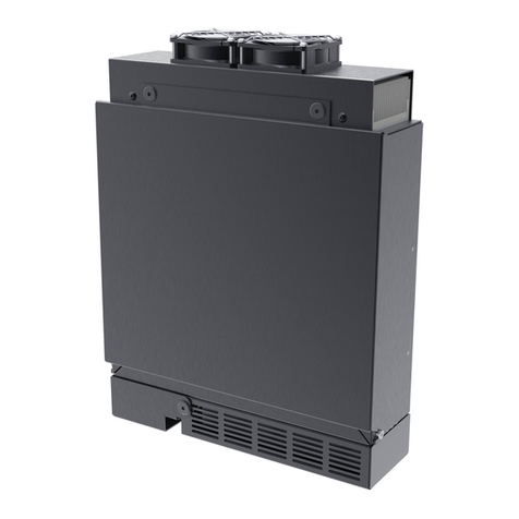
Outdoor Wireless Kit
2300 White Oak Circle • Aurora, Il 60502 • (800) 865-2112 • Fax: (800) 359-6500 • www.peerless-av.com

2 of 22 2016-09-07 SHEET #: 180-9091-1
Note: Read entire instruction sheet before you start installation and assembly.
Table of Contents
Parts List.............................................................................................................................................................................3, 4
Enclosure Wall installation......................................................................................................................................................5
Enclosure Installation to ESA763PU Articulating Wall Mount.................................................................................................7
Enclosure Installation to EPT650 Tilt Wall Mount.................................................................................................................16
Wireless Receiver Setup......................................................................................................................................................18
Tools Needed for Assembly
• stud finder ("edge to edge" stud finder is recommended)
• phillips screwdriver
• drill
• 5/16" (8 mm) bit for concrete and cinder block wall
• 5/32" (4 mm) bit for wood stud wall
• level
• 7/16" open end wrench
• 5mm allen wrench
• 6mm allen wrench
• Do not begin to install your Peerless product until you have read and understood the instructions and warnings
contained in this Installation Sheet. If you have any questions regarding any of the instructions or warnings, for US
customers please call Peerless customer care at 1-800-865-2112, for all international customers, please contact
your local distributor.
• This product should only be installed by someone of good mechanical aptitude, has experience with basic building
construction, and fully understands these instructions.
• Due to outdoor environmental conditions such as heavy snow, hail, rain, etc. the environmental mount and
hardware must be inspected at least once a year. This product should not be exposed to high winds. A qualified
installer or inspector must check for signs of rust, loose fasteners, bent metal, etc. If evidence of excessive wear,
deterioration or any unsafe condition is observed, this product must be taken out of service immediately. Direct all
inquiries to customer care if you have any questions.
• Make sure that the supporting surface will safely support the combined load of the equipment and all attached
hardware and components.
• Never exceed the Maximum Load Capacity. See page one.
• If mounting to wood wall studs, make sure that mounting screws are anchored into the center of the studs. Use of
an "edge to edge" stud finder is highly recommended.
• Always use an assistant or mechanical lifting equipment to safely lift and position equipment.
• Tighten screws firmly, but do not overtighten. Overtightening can damage the items, greatly reducing their holding
power.
• This product was designed to be installed on the following wall construction only;
WALL CONSTRUCTION HARDWARE REQUIRED
• Wood Stud Included
•Wood Beam Included
•Solid Concrete Included
•Cinder Block Included
• Metal Stud Contact Qualified Professional
• Brick Contact Qualified Professional
• Other or unsure? Contact Qualified Professional
WARNING

3 of 22 2016-09-07 SHEET #: 180-9091-1
HDS-OWK-%
#traP.ytQnoitpircseD
Awireless receiver assembly, outdoor 1 180-1427
B0230-0952rohcnaetercnoc
C3305-0252wercsdoow"5.2x41#
Dcable tie .187 x 7.5 lg. 2 590-1168
Ecable tie .04 x 5.75 lg. 4 560-9711
Fpush-in round plastic plug, 3/8" 4 590-9465
G1/4-20 x 1/2 socket head screw 6 500-2093
H3105-0356
02-4/1tunkcol
I8649-0951htaehstnemeganamelbac
Jenclosure mounting bracket, small 2 120-T1195
Kenclosure mounting bracket, large 2 120-T1196
L6469-0651hcnerwnellamm4
Parts List
BCDE
GH
JL
F
K
I
A
Parts may appear slightly different than illustrated.
Before you begin, make sure all parts shown are included with your product.

4 of 22 2016-09-07 SHEET #: 180-9091-1
Adapter Bracket Fasteners
M4 x 12 mm (6)
(510-D1079)
M4 x 25 mm (4)
(510-D1082)
M5 x 12 mm (4)
(520-D1064) M5 x 25 mm (4)
(520-D1122)
M8 x 12 mm (6)
(520-D1068)
M8 x 40 mm (4)
(520-D1152)
M8 x 25 mm (4)
(520-D1101)
I.D. .34" (4)
(540-1059)
I.D. .22" (4)
(540-1057)
M6 x 30 mm (4)
(520-D1067)
M6 x 12 mm (4)
(520-D1050)
M6 x 25 mm (4)
(520-D1211)
M6 x 20 mm (4)
(520-D1554)
multi-washer (6)
(580-D1036)
ISSUED:06-12-12 SHEET#: 180-9023-1
User Manual and Installation Guide
Pro Wireless Multimedia Kit
Models:
HDS200
HDS200-2
HDS200-3
HDS200-4 READY
®
Step7 While turning on the display device the HD Flow Pro Wireless Multimedia units will be going through the star tup process. This process may
takeupto two minutes to complete. The Power/Link indicator lights on the Transmitter and the Receiverwill b e flashing at first. Flashing indicates
thattheunits are establishing a secure connection. Wait until the connection is successfully established, indicated by the Power/Linkindic ator
lightbecomingsolid.
Minutes
2
1xTransmitter
1xReceiver
2xStand
1xRemote Control
1xIR Flasher
1xIR Extender
1xComponent Adaptor
2xPower Adapter
1xQuick Start Guide
1xUsers Manual
Step2 Connect the provided IR Flasher to the IR-OUT port on the Transmitter.
Findthelocation of the IR window on your source device and adhere the
IRFlashereye directly over the IR window on your source device.
NOTE:OneIRFlasher ey e is to be used for one comp onent device.
Step4 Install the IR Extender by plugging in the provided IR E xtender in to
theIR-INport on the Receiver and adhering the other end of the IR Extender
toavertical surface near the output device. Ensure that the IR Ex tenderis in
alineof sight to the remote control that controls your source devices.
NOTE:ForMulticastmodels, receivers two, three and four do not come wi th an IR Extender. AdditionalIREx tenders
(HDS-IRE)canbep urchased separ ately; visit peerle ss-av.com for more inform ation.
Step6 Turn on your display device (TV, monitor, projector,etc .).
Step3 Connect the display device (TV, monitor, projector, etc.)
totheReceiver.
Step5 Power-up the HD Flow Pro Devices.
1.Plugin the power adapter for the Transmitter and the Receiver to nearby
availablepower outlets.
2.Plugin the power adapter endtothe Transmitter and then to the Receiver.
3.Theunits will automatically turn-on. The aver age power-on/synctime
isapproximately two minutes.
What’sin the Box
Installationan d Setup
TroubleshootingTips
TipTheIR window
maybeeasierto
locatewithadirect
lightshiningon
sectionsofthe
frontpanelof the
componentdevice.
Asmallflashlight
workswell.
Power/Source
SelectionButton
TipRepeatSteps
3-11toconnect
morethanone
Receiverunit
(HDS200-2,
HDS200-3,
HDS200-4).
Step1 Connect the Transmitter to the source devices
(Blu-ray™Discplayer,set top box, gaming console, etc.).
Step9 Turn on the desired source device that is connected to
theTransmitter.
Step11 Play the source device content and enjoy up to Full HD 1080p
wirelessentertainmentexperience.
• Check the media source resolution. The display device must be able
tosupportthe resolution of the media source that is being streamed.
UtilizingtheINFO button will allow you to see the resolution data that
thedisplaydevice supports. If the display device suppor ts the highest
resolutionof720p but the source device is outputting 1080p content,
thecontentneeds to be down-scaled to the maximum resolution of the
displaydevice,in this case 720p.
ReceiverOutputIn dicator Light Blinks:
• Make sure that your display device, source device and the HD Flow Pro units
areallturned ON and the Receiver is properly connected to the output device.
• Verify that the Receiver is set to the appropriate output port.
• Check the resolution setting of your source device. This may need to be
changedtoa resolution supported by the HD Flow Pro unit. Reference
theResolutionChart in the HD Flow Pro Manual for compatibility.
Referenceyoursource devices’ manual for instruction on changing
theoutputresolution.
Iftheabove troubleshooting tips donot re solvethe issues for a unicast setup,
pleasereferencethe Factory Reset Section of the HD Flow Pro Manual. For a
multicastsystemconfiguration, please contact Peerless-AV Customer Care at
800-856-2112forfurther instruction.
Step8 Select the output that connects the Receiver to the display using
thePower/SourceSelection Button or the provided remote control.
Theoutputindicator light will become solid and the HD Flow logo will
appearonthe display device.
Step10 Select the desired source or device input on the Transmitter
usingthePower/Source Selection Button on the remote control.
Transmitterand/orReceiverIndicator Lights are all Blinking:
• The HD Flow Pro units are establishing a connection. It can take
uptotwo minutes for the HD Flow Pro units to establish a complete
connection.Ifafter two minutes have passed and the units have not
establishedaconnection, unplug the power cable, wait 30 seconds
andreconnectthe power supply to the units.
TransmitterorReceiverPower Indicator Light is OFF:
• Check and verify the power supply connection.
TransmitterInputIndicatorLight Blinks:
• Make sure that your source device is turned ON and the cable
isproperlyconnected.
• Verify that the Transmitter is set to the appropriate input port.
• Check the resolution from your source device. This may need to
bechangedto a resolution supported by the HD Flow Pro Wireless
MultimediaKit.Reference the Resolution Chart in the HD Flow Pro
Manualforcompatibility. Reference your source devices’ manual
forinstructionon changing the output resolution.
ReceiverPowerIndicator Light Blinks:
• Verify that the HD Flow Pro Transmitter and Receiver are within
therecommendedrange of 131 feet. Physical obstructions such as
walls,floorsand ceilings between the Transmitter and Receiver may
decreasethestrength of the connection sig nal and reducethe over all
transmissionrange.
Ifaconnection has been established and the HD Flowlogo can be seen
onthedisplay device, but contentis not playing:
• Make sure that the input/output cables are properly connected.
• Verify that the Transmitter is set to the appropriate input port.
WarningDo not place the HD Flow
Prounitsnear other devices that
emitexcessiveamounts of heat.
Increasedtemperaturesmay
causetheHD Flow Pro Transmitter
orReceiverunit to malfunction
orstopworking.
tthdi l di (TV it j t t )
S
teps
ect
ne
t
QuickStartGuide for HD Flow Pro Wi reless Multime dia Kit -LIT-0906
Power/Source
SelectionButton
©2012PeerlessInd ustries, In c. Peerless -AV™ is a tradema rk of Peerless I ndustries , Inc. All righ ts reserv ed.
HDFlow™isa trademark o f I Do It, LTD. Other par ties’ mark s are the proper ty of their res pective own ers. hdflow.com
Quick Start Guide
PROWIRELESSMULTIMEDIA KIT
ModelNo.HDS200 (-2, -3, -4)
READY
®
Additional Wireless Components
wireless transmitter (1) vga to rca adapter (1) remote (1)
ir flasher (1)
plastic stand (1)
instruction sheet (1)12v power adapter (1)3v battery (1)
install guide (1)
hdmi cable (2)

5 of 22 2016-09-07 SHEET #: 180-9091-1
Enclosure Wall Installation
Use a stud finder to locate the edges of the stud. Use of an
edge-to-edge stud finder is highly recommended. Based
on its edges, draw a vertical line down the stud’s center.
Place enclosure on wall as a template, making sure that two
vertical mounting holes are over the stud centerline. Level the
enclosure, and mark the center of the two holes. Drill two 5/32"
(4mm) dia. holes 2-1/2" (64mm) deep. Make sure that the
enclosure is level, secure it using two #14 x 2-1/2" wood screws
(C) as shown.
Skip to step 7.
A
C
• Installer must verify that the supporting surface will safely support the combined load of the equipment and all
attached hardware and components.
• Tighten wood screws so that the enclosure is firmly attached, but do not overtighten. Overtightening can damage
the screws, greatly reducing their holding power.
• Never tighten in excess of 80 in. • lb (9 N.M.).
• Make sure that mounting screws are anchored into the center of the stud. The use of an "edge to edge" stud finder
is highly recommended.
• Hardware provided is for attachment of mount through standard thickness drywall or plaster into wood studs. Install-
ers are responsible to provide hardware for other types of mounting situations.
WARNING
2
Open the wireless receiver enclosure (A) and unplug the wireless receiver power cord from the wireless receiver.
Remove the wireless receiver and sub panel assembly as shown in fig. 1.1. Choose two holes for securing the
wireless receiver enclosure (A). Press in plastic plug (F) into the four remaining holes shown in figure 1.2.
1
fig. 1.1 fig. 1.2
A
F
A
WIRELESS
RECEIVER
SUB PANEL
ASSEMBLY
WIRELESS
RECEIVER
POWER CORD
MOUNTING
HOLES
Installation to Single Wood Stud Wall

6 of 22 2016-09-07 SHEET #: 180-9091-1
Make sure that the enclosure is level, use it as a
template to mark two mounting holes. Drill two 5/16"
(8mm) dia. holes to a minimum depth of 2-1/2"
(64mm). Insert anchors (B) in holes flush with wall
as shown (right). Place the enclosure over anchors
and secure with two #14 x 2-1/2" screws (C). Level,
then tighten all fasteners.
C
CINDER BLOCK
SOLID CONCRETE
AB
1
3
2
B
Drill holes and insert anchors (B).
Place enclosure (A) over anchors (B) and secure with screws (C).
Tighten all fasteners.
A
B
C
concrete
surface
2
• Verify that you have a minimum of 1-3/8" (35mm) of actual concrete thickness in the hole to be used for the con-
crete anchors. Do not drill into mortar joints! Be sure to mount in a solid part of the block, generally 1" (25mm) mini-
mum from the side of the block. Cinder block must meet ASTM C-90 specifications. It is suggested that a standard
electric drill on slow setting is used to drill the hole instead of a hammer drill to avoid breaking out the back of the
hole when entering a void or cavity.
• Concrete must be 2000 psi density minimum. Lighter density concrete may not hold concrete anchor.
• Make sure that the wall will safely support four times the combined load of the equipment and all attached hardware
and components.
WARNING
CUTAWAY VIEW
INCORRECT CORRECT
wall
plate wall
plate
plaster/
drywall plaster/
drywall
concrete concrete
• Tighten screws so that wall plate is firmly attached,
but do not overtighten. Overtightening can damage
screws, greatly reducing their holding power.
• Never tighten in excess of 80 in. • lb (9 N.M.).
• Always attach concrete expansion anchors directly
to load-bearing concrete.
• Never attach concrete expansion anchors to
concrete covered with plaster, drywall, or other
finishing material. If mounting to concrete surfaces
covered with a finishing surface is unavoidable,
the finishing surface must be counter bored as
shown below. Be sure concrete anchors do not
pull away from concrete when tightening screws. If
plaster/drywall is thicker than 5/8" (16mm), custom
fasteners must be supplied by installer.
WARNING
Skip to step 11.
Enclosure Wall Installation to Solid Concrete or Cinder Block

7 of 22 2016-09-07 SHEET #: 180-9091-1
NOTE: If display has a VESA 400 horizontal
mounting pattern, skip to step 4 on page 8.
NOTE: For VESA 200x200 or VESA 200x100
mount hole patterns, skip to step 6 on page 11.
Remove four 1/4-20 x .6" screws using 5 mm allen
wrench and loosen two 1/4-20 x 1.25" screws 1/2
turn to allow for display bracket adjustment.
1/4-20 x .6" SCREWS
1/4-20 x 1.25" SCREWS
3
To prevent scratching the display, set a cloth on a flat, level surface that will support the weight of the display.
Place display face side down and refer to display manufacturers instructions for removing obstructions from the
back of the display. Adjust display brackets to align with display mounting holes.
Measure horizontal mounting hole pattern and choose fixed stop-position from chart below.
3-1
FIXED STOP-POSTION #2
FIXED STOP-POSTION #1
FIXED STOP-POSTION #3
horizontal mounting hole pattern fixed stop-position
10-3/4" - 16-1/16" (273 - 408 mm) #1
15-1/16" - 21-9/16" (383 - 548 mm) #2
20-7/16" - 27-9/16" (519 - 700 mm) #3
Enclosure Installation to ESA763PU Articulating Wall Mount

8 of 22 2016-09-07 SHEET #: 180-9091-1
Open the wireless receiver enclosure (A) and unplug the wireless receiver power cord from the wireless receiver.
Remove the wireless receiver and sub panel assembly as shown in fig. 4.1. Loosely attach the small enclosure
mounting brackets (J) to the wireless receiver enclosure (A) with two 1/4-20 x 1/2 socket head screws (G) and
two 1/4-20 nuts (H) as shown in fig. 4.2. NOTE: The enclosure mounting bracket can be installed with the inside
notch facing downward if additional side to side adjustment is needed. Position and tighten the four 1/4-20 x 1/2
socket head screws (G) using 4mm allen wrench (L). Press in two plastic plugs (F) into holes shown in figure 4.2.
Attach the mounting brackets (J), open end of notch facing downward, to the left display bracket with two
1/4-20 x 1/2 socket head screws (G) and two 1/4-20 nuts (H) as shown in fig. 5.1.
Adjust the position of the enclosure (A) to your desired location as shown in fig. 5.2 Once in position, tighten the
four 1/4-20 x 1/2 socket head screws (G) using 4mm allen wrench (L).
4
5
fig. 4.1
fig. 5.1 fig. 5.2
fig. 4.2
H
JG
A
A
A
H
A
J
F
G
H
WIRELESS
RECEIVER
SUB PANEL
ASSEMBLY
WIRELESS
RECEIVER
POWER CORD
DISPLAY
BRACKET
INSIDE NOTCH

9 of 22 2016-09-07 SHEET #: 180-9091-1
Select the screws from the baffled fastener pack that best fit your display and secure to display following step 5-2
on page 10.
NOTE: Top and bottom mounting holes must be used for attaching display brackets. Middle holes should also be
used where the fasteners and displays allow.
Verify that all holes are properly aligned, then tighten screws using a phillips screwdriver.
CENTER DISPLAY BRACKETS VERTICALLY AND
HORIZONTALLY ON BACK OF DISPLAY
NOTE: "X" dimensions should be equal.
"Y" dimensions should be equal.
• Tighten screws so display brackets are firmly attached to display. Do not tighten with excessive force.
Overtightening can cause stress damage to screws, greatly reducing their holding power and possibly causing
screw heads to become detached. Tighten to 40 in. • lb (4.5 N.M.) maximum torque.
• If screws don't get three complete turns in the display inserts or if screws bottom out and bracket is still not tightly
secured, damage may occur to display or product may fail.
WARNING
Installing Adapter Brackets to Display
5-1
DISPLAY
DISPLAY BRACKETS
X
X
YY

10 of 22 2016-09-07 SHEET #: 180-9091-1
NOTE: enclosure removed for clarity.
Begin with the longest length screw, hand thread
screw through multi-washer, display brackets and
spacer in that order into display as shown below.
Screw must make at least three full turns into the
mounting hole and fit snug into place. Do not over
tighten. If screw cannot make three full turns into
the display, select a shorter length screw from
the baffled fastener pack. Repeat for remaining
mounting holes, level display brackets and tighten
screws.
5-2 DISPLAY MULTI-WASHER
DISPLAY BRACKET
SPACER SCREW
Center display brackets horizontally and vertically
on back of display. Tighten two 1/4-20 x 1.25"
screws. Reinstall four 1/4-20 x .6" screws using
a 5 mm allen wrench into appropriate fixed-stop
position from chart on page 7.
5-3 1/4-20 x 1.25" SCREWS
1/4-20 x .6" SCREWS

11 of 22 2016-09-07 SHEET #: 180-9091-1
Remove four 1/4-20 x .6" screws using a 5mm allen wrench
and loosen two 1/4-20 x 1.25" screws 1/2 turn to allow for
display bracket adjustment.
Remove four 1/4-20 self tapping screws to detach display brackets from outer mount holes of the universal
adapter bracket using a 5mm allen wrench as shown in figure 6.1. Reinstall four 1/4-20 self tapping screws to
secure display brackets to inner set of mounting holes on the universal adapter bracket as shown in figure 6.2.
1/4-20 SELF
TAPPING SCREWS 1/4-20 SELF
TAPPING SCREWS
DISPLAY
BRACKETS DISPLAY
BRACKETS
INNER
MOUNTING
HOLES
OUTER
MOUNTING
HOLES
fig. 6.1 fig. 6.2
Enclosure Installation to ESA763PU Articulating Wall Mount
VESA 200 x 200 or VESA 200 x 100 Mounting Pattern
To prevent scratching the display, set a cloth on a
flat, level surface that will support the weight of the
display. Place display face side down and place the
universal adapter bracket onto display.
6-1
6
BB
1/4-20 x .6" SCREWS
1/4-20 x 1.25" SCREWS

12 of 22 2016-09-07 SHEET #: 180-9091-1
6-2
DISPLAY
BRACKET
GA
K
H
G
H
F
fig. 6.3 fig. 6.4
fig. 6.5
Slide universal adapter bracket to the side to expopse the display bracket mounting slots. Attach the mounting
brackets (K), open end of notch facing downward, to the left display bracket with two 1/4-20 x 1/2 socket head
screws (G) and two 1/4-20 nuts (H) as shown in fig. 6.5.
6-3
Open the wireless receiver enclosure (A) and unplug the wireless receiver power cord from the wireless receiver.
Remove the wireless receiver and sub panel assembly as shown in fig. 6.3. Loosely attach the large enclosure
mounting brackets (K) to the wireless receiver enclosure (A) with two 1/4-20 x 1/2 socket head screws (G) and
two 1/4-20 nuts (H) as shown in fig. 6.4. NOTE: The enclosure mounting bracket can be installed with the inside
notch facing downward if additional side to side adjustment is needed. Position and tighten the four 1/4-20 x 1/2
socket head screws (G) using 4mm allen wrench (L). Press in two plastic plugs (F) into holes shown in figure 6.4.
A
WIRELESS
RECEIVER
SUB PANEL
ASSEMBLY
WIRELESS
RECEIVER
POWER CORD

13 of 22 2016-09-07 SHEET #: 180-9091-1
Align one display bracket with one set of display mounting holes. Place spacers between display bracket and
display. Begin with the longest length screw, hand thread screw through the multi-washer, display brackets, and
spacer into display as shown. Screw must make at least three full turns into the mounting hole and fit snug into
place. Do not over tighten. If screw cannot make three full turns into the display, select a shorter length screw
from the baffled fastener pack. Center display brackets vertically and tighten screws.
Slide universal adapter bracket to the opposite side to expopse the display bracket mounting slots. Place spacers
between display bracket and display. Begin with the longest length screw, hand thread screw through the multi-
washer, display brackets, and spacer into display as shown. Screw must make at least three full turns into the
mounting hole and fit snug into place. Do not over tighten. If screw cannot make three full turns into the display,
select a shorter length screw from the baffled fastener pack. Center display brackets vertically and tighten
screws.
SCREW
SCREW
MULTI-
WASHER
MULTI-
WASHER
SPACER
SPACER
DISPLAY
BRACKET
DISPLAY
BRACKET
6-4
6-5

14 of 22 2016-09-07 SHEET #: 180-9091-1
Center the universal adapter bracket horizontally on back of display as shown in figure 6.6.
Tighten two 1/4-20 x 1.25" screws. Reinstall four 1/4-20 x .6" screws using a 5 mm allen wrench into fixed-stop
position 1 as shown in figure 6.7.
6-6
6-7
fig. 6.7
fig. 6.8
FIXED STOP POSITION #1 WITH
1/4-20 x .6" SCREWS
fig. 6.6
1/4-20 x 1.25" SCREWS
N
G
Adjust the position of the enclosure (A) to your desired location as shown in fig. 6.8 Once in position, tighten the
four 1/4-20 x 1/2 socket head screws (G) shown in fig. 6.8 using 4mm allen wrench (L) and a 7/16" open end
wrench.

15 of 22 2016-09-07 SHEET #: 180-9091-1
Hook M10 x 15 mm screws into keyslots of wall arm adapter plate as shown figure 7.1.
Insert two M10 x 15 mm screws included with wall arm into bottom holes of wall arm adapter plate as shown in
figure 7.2. Tighten all fasteners with a 6 mm allen wrench.
Skip to step 11.
7-1
WALLARMADAPTER PLATE
DISPLAY NOT
SHOWN FOR
CLARITY
DISPLAY NOT
SHOWN FOR
CLARITY
• Do not lift more weight than you can handle. Use additional man power or mechanical lifting equipment to safely
handle placement of the display.
• Do not tighten screws with excessive force. Overtightening can cause damage to mount. Tighten M10 x 15 mm
screws (E) to 40 in. • lb. (4.52 N.M.) maximum torque.
WARNING
Mounting Flat Panel Display
7
1/4"
M10 X 15 MM SCREW
fig. 7.1
fig. 15.2
M10 X 15 MM SCREW
WALLARM ADAPTER PLATE
ADAPTER PLATE

16 of 22 2016-09-07 SHEET #: 180-9091-1
Open the wireless receiver enclosure (A) and unplug the wireless receiver power cord from the wireless receiver.
Remove the wireless receiver and sub panel assembly as shown in fig. 8.1. Loosely attach the small enclosure
mounting brackets (J) to the wireless receiver enclosure (A) with two 1/4-20 x 1/2 socket head screws (G) and
two 1/4-20 nuts (H) as shown in fig. 8.2. NOTE: The enclosure mounting bracket can be installed with the inside
notch facing downward if additional side to side adjustment is needed. Position and tighten the four 1/4-20 x 1/2
socket head screws (G) using 4mm allen wrench (L). Press in two plastic plugs (F) into holes shown in figure 8.2.
8
Enclosure Installation to EPT650 Tilt Wall Mount
fig. 8.1 fig. 8.2
A
F
J
H
G
WIRELESS
RECEIVER
SUB PANEL
ASSEMBLY
WIRELESS
RECEIVER
POWER CORD
INSIDE NOTCH
Attach the mounting brackets (J), open end of notch facing downward, to the left tilt bracket with two
1/4-20 x 1/2 socket head screws (G) and two 1/4-20 nuts (H) as shown in fig. 9.1. Adjust the position of the
enclosure (A) to your desired location and tighten the four 1/4-20 x 1/2 socket head screws (G) using 4mm allen
wrench (L).
9
fig. 9.1
H
A
G
LEFT TILT BRACKET

17 of 22 2016-09-07 SHEET #: 180-9091-1
To prevent scratching the display, set a cloth on a flat, level surface that will support the weight of the display. Place
display face side down. If display has knobs on the back, remove them to allow the adapter brackets to be at-
tached. Place adapter brackets on back of display, align to holes, and center on back of display as shown below.
Attach the adapter brackets to the back of the display using the appropriate combination of screws, multi-washers,
and spacers as shown in figure 10.1.
NOTE: "X" dimensions should be equal.
CENTER BRACKETS
VERTICALLY ON BACK
OF DISPLAY
X
X
TILT LOCKING SCREWS
FACE OUT
10
Notes:
• The number of fasteners used will vary,
depending upon the type of display.
• Multi-washers and spacers may not
be used, depending upon the type of
display.
• Use the corresponding hole in the multi-
washer that matches your screw size as
shown.
MEDIUM HOLE FOR M5 SCREWS
SMALL HOLE FOR M4 SCREWS
LARGE HOLE FOR M6 SCREWS
MULTI-WASHER
Installing Tilt Brackets
NOTE: Top and bottom mounting holes on display must be used for attaching brackets.
NOTE: Be sure to attach tilt brackets with tilt locking screws facing outward as shown below. Verify that all holes
are properly aligned, and then tighten screws using a phillips screwdriver.
• Tighten screws so adapter brackets are firmly attached. Do not tighten with excessive force. Overtightening
can cause stress damage to screws, greatly reducing their holding power and possibly causing screw heads to
become detached. Tighten to 40 in. • lb (4.5 N.M.) maximum torque.
• If screws don't get three complete turns in the display inserts or if screws bottom out and bracket is still not tightly
secured, damage may occur to display or product may fail.
WARNING

18 of 22 2016-09-07 SHEET #: 180-9091-1
If you have any questions, please call Peerless customer care at 1-800-865-2112.
Begin with longer length screw, hand thread through multi-washer, tilt bracket and spacer in that order into display
as shown below. Screw must make at least three full turns into the mounting hole and fit snug into place. Do not
over tighten. If screw cannot make three full turns into the display, select a longer length screw from the baffled
fastener pack. Repeat for remaining mounting holes, level brackets and tighten screws.
10-1
DISPLAY
MULTI-WASHER
SCREW
TILT BRACKET
fig. 10.1
SPACER

19 of 22 2016-09-07 SHEET #: 180-9091-1
Insert the sub panel assembly into the wireless receiver enclosure (A) above the foam pads as shown. Push
the sub panel assembly towards the rear of the until it makes contact with the back wall and the bottom of the
enclosure .
Insert an extension cord (not included) through the cord access hole in the bottom of the enclosure as shown. Plug
entension cord into the triple tap grounded outlet.
11
TRIPLE TAP
GROUNDED OUTLET
EXTENSION CORD
CORD ACCESS
HOLE
12
Wireless Receiver Setup
FOAM PADS
A
SUB PANEL
ASSEMBLY

20 of 22 2016-09-07 SHEET #: 180-9091-1
Insert the power cord from your display through the cord access hole in the bottom of the enclosure as shown. Plug
the power cord into the triple tap grounded outlet. Coil up the excess cord and secure with a cable tie (E). Store
excess cord inside enclosure.
Remove the tie from the IR receiver and insert the
end through the cord access hole in the bottom of the
enclosure as shown.
CORD ACCESS
HOLE
DISPLAY POWER
CORD
IR RECEIVER
Position the IR receiver on the front of the display
within line of sight of your remote as shown. Remove
the adhesive backing from the IR receiver eye and
attach to the display. Coil up the excess cord near
the wireless receiver enclosure and secure with a
cable tie (E). Store excess cord inside enclosure.
15
IR RECIEVER
13
14
Table of contents
Other peerless-AV Enclosure manuals

peerless-AV
peerless-AV KIP640-S User manual

peerless-AV
peerless-AV KIL640 User manual

peerless-AV
peerless-AV FPE47F-S Guide

peerless-AV
peerless-AV KL546-TOSHIBA02 Guide

peerless-AV
peerless-AV KL540-S Guide

peerless-AV
peerless-AV XACE-01 User manual

peerless-AV
peerless-AV KIP640 User manual

peerless-AV
peerless-AV KIL655-S-EUK User manual

peerless-AV
peerless-AV CL-ENCL68 User manual
Popular Enclosure manuals by other brands

Akitio
Akitio Taurus Mini Super-S user manual

Mustang Sampling
Mustang Sampling Pony Installation operation & maintenance

ELBOX
ELBOX BlackBOX 1200 Assembly manual

CommScope
CommScope FOSC-450-BS Installation instruction

Dormakaba
Dormakaba Crane 2000LE owner's manual

Clas Ohlson
Clas Ohlson GD25604 quick start guide