peerless-AV XACE-01 User manual

12019-09-26 #:180-9135-4 (2020-08-25)
XACE-01, XACE-02
Visit website for translated user guide.
Visite la página web para ver la traducción de la
guía del usuario.
Veuillez consulter le site internet pour la traduction
du guide de l'utilisateur.
Siehe Website für Bedienungsanleitung auf Deutsch.
Visitare il sito web per la guida dell'utente tradotta.
ENG
ESP
FRN
DEU
ITL
RUS
https://www.peerless-av.com/products/xace-01

22019-09-26 #:180-9135-4 (2020-08-25)
Relevant Information
Record your products model and serial number here for future reference. Keep this user manual in an accessible
location in the event service is required.
Model Number ____________________________________
Serial Number ____________________________________
Electrical Code
Note: To the system installer: Outlet shall be installed near the equipment and shall be easily accessible.
Installation shall incorporate UL Listed external surge protection rated 2500 Vpk or less, for 150 to 300 Vac mains,
installed in accordance with ANSI/NFPA 70 or applicable local codes.
FCC STATEMENT
This equipment has been tested and found to comply with the limits for a Class A digital device, pursuant to Part
15 of the FCC Rule. These limits are designed to provide reasonable protection against harmful interference in a
residential installation. This equipment generates, uses and can radiate radio frequency energy and, if not installed
and used in accordance with these instructions, may cause harmful interference to radio communications; however,
there is no guarantee that interference will not occur in a particular installation. If this equipment does cause harmful
is encouraged to try to correct the interference by one or more of the following measures:
1. Increase the separation between the equipment and receiver.
2.
3.
This device complies with Part 15 of the FCC Rules. Operation is subject to the following two conditions:
• This device may not cause harmful interference.
• This device must accept any interference received, including interference that may cause undesired operation.
Power Source
The product must be connected to a mains socket outlet with a protective grounding connection.
The mains plug is used as the disconnect device and shall remain readily accessible.
To prevent electric shock, do not use with an extension cord, receptacle, or other outlet unless the blades and
ground terminal can be fully inserted to prevent blade exposure.
All secondary lines must be routed through grounded conduit and kept separate from AC line.
Symbols
ENG
WARNING
ENG
Tools Needed for Assembly.
ENG
Do not overtighten screws.
ENG

32019-09-26 #:180-9135-4 (2020-08-25)
GENERAL SAFETY PRECAUTIONS
Read before operating equipment
Thank you for purchasing our product. Before using it, please read this user guide carefully and follow the
instructions for safe operation. Please keep this manual for future reference and always include it when transferring
• In case of product malfunction or unusual events such as electrical burning smell, smoke, or loss of
manufacturer.
• Do NOT disassemble, modify or service product in any way other than that contained in this instruction. Any
• Do NOT touch wires, electrical cables or plugs when lightning or thunder is present or with wet hands
• Do NOT submerge in water.
• Do NOT destroy, process, or place close to any heat source.
• Do NOT install near poisonous gas or chemically unstable atmosphere.
•
• Do NOT install the product in unstable locations or near moving objects, constantly vibrating equipment, or
uneven surfaces.
•
• Do NOT operate the product if it has been dropped or struck. Severe physical impact to the product may
cause components to fall out of place within and break.
• Do NOT bend or twist electrical cords, electrical plugs, cables, or wires with excessive force.
• Do NOT block ventilation slots or place any heavy object on the product.
• Use properly rated electrical voltage.
• Do NOT use any electrical sockets or power strips with many other devices jointly plugged in. Use a single,
directly dedicated and rated GFCI electrical outlet for the product for safe operation.
• Do NOT move or transport with any cables (electrical, content connectivity) plugged in to the source devices.
•
plug and not the cord.
• Do not defeat the safety purpose of the polarized or grounding type electrical plug. A polarized plug has two
blades with one wider than the other. A grounding type plug has two blades and a third grounding prong. The
consult an electrician for replacement of the obsolete outlet.
• Protect the electrical cord from being walked on or pinched particularly at plugs, convenience receptacles, and
the point where they exit from the apparatus.
• Do NOT climb on the product.
•
•
•
WARNING
42019-09-26 #:180-9135-4 (2020-08-25)
Power Consumption
(Wattage)
Active Enclosure
Temperature Dierential
20W
30W
50W
Your device will run at a higher or lower temperature than the outside ambient temperature. To verify your
device will function under typical operating conditions, consult the device's manual to identify and record the
power consumption ( _______ wattage) and maximum operating temperature (_______ °).
consumption (wattage).
For example, if your device has a 20W power consumption, the temperature inside the active enclosure will
ENG
OPERATING PARAMETERS
If active enclosure temperature exceeds device's
maximum temperature, the product may be damaged or
destroyed, voiding the warranty.
CAUTION
Device(s) (not included)
Active Enclosure
20 Watts 30 Watts 50 Watts
102 BTU
Load in watts and BTU
Temperature Dierential vs. Load
171 BTU 205 BTU

52019-09-26 #:180-9135-4 (2020-08-25)
OPERATING PARAMETERS
Two device maximum. Do not stack devices.
CAUTION
internal surfaces for appropriate ventilation.
CAUTION
Part
Grommet
Size
Grip
Range
E3mm
F
G5mm
-
-7mm
-
Hdual 3mm
I
Jdual 5mm
K
-dual 7mm
-
-blank N/A

62019-09-26 #:180-9135-4 (2020-08-25)
Parts (Before beginning, make sure you have all parts shown below).
ENG
Parts List XACE-01
Part #
XACE-02
Part #Description Qty
Aenclosure assembly 1
B 1
Cvelcro strap 1
Dwire gauge 1
E3mm grommet 1
F 1
G5mm grommet 1
Hdual 3mm grommet 1
I 1
Jdual 5mm grommet 1
K 1
LM5 x 10mm phillips screw
M 2
A (1)
enclosure asy
D (1)
wire gauge
H (1)
dual 3mm
grommet
I (1)
grommet
J (1)
dual 5mm
grommet
K (1)
grommet
E (1)
3mm grommet F (1)
G (1)
5mm grommet
C (1)L (4)
M (2)
velcro strap M5 x 10mm
B (1)
wrench
12357

72019-09-26 #:180-9135-4 (2020-08-25)
1-1
Loosen
ENG
1-2
Remove enclosure cover plate.
ENG
B
electricity. Failure to do so may result in injury or death.
WARNING
A
Optional security screws.
ENG
B
M

82019-09-26 #:180-9135-4 (2020-08-25)
2-1
2-2
ENG loosen
Remove.
ENG

92019-09-26 #:180-9135-4 (2020-08-25)
3-2
3-1
C
ENG not included
Two device maximum. Do not stack devices.
CAUTION
internal surfaces for safe ventilation.
CAUTION
Refer to operating parameters before attaching
device.
ENG
ENG tighten

10 2019-09-26 #:180-9135-4 (2020-08-25)
4-1
4-2
Remove gasket cover, and save hardware.
ENG B
ENG not included
ENG Loosen. Do not remove.

11 2019-09-26 #:180-9135-4 (2020-08-25)
Remove cable gland and save hardware.
ENG
5
B

12 2019-09-26 #:180-9135-4 (2020-08-25)
6
Remove unused grommets. Do not remove preinstalled cable.
ENG

13 2019-09-26 #:180-9135-4 (2020-08-25)
D
12357
7-1
7-2
ENG
ENG Grommet must seal around cable.
Part
Grommet
Size
Grip
Range
E3mm
F
G5mm
-
-7mm
-
Hdual 3mm
I
Jdual 5mm
K
-dual 7mm
-
-blank N/A

14 2019-09-26 #:180-9135-4 (2020-08-25)
8-1
8-2
Slide grommets into enclosure, aligning grooves of grommet with grooves in cable gland.
ENG
ENG Align grooves
Top View
ENG Note orientation of red edge
Front View

15 2019-09-26 #:180-9135-4 (2020-08-25)
9
ENG Orient grommet using red edges. Red edges must join in the
center. Failure to follow these instructions can result in the
product being damaged or destroyed, voiding the warranty.
CAUTION
RED EDGES
MUST JOIN
RED EDGES
ENG
CAUTION

16 2019-09-26 #:180-9135-4 (2020-08-25)
10-1
10-2
ENG Groove must align and face inside enclosure.
Reassemble cable gland.
ENG
B

17 2019-09-26 #:180-9135-4 (2020-08-25)
11-1
11-2
Replace gasket cover, routing cables between inner and outer gasket covers.
ENG
Route cables between gap in gasket cover.
ENG
B
B
Tighten.
ENG

18 2019-09-26 #:180-9135-4 (2020-08-25)
12-1
Replace enclosure cover plate.
ENG
12-2
15 in. • lb (1.7 N.M.).
B
CAUTION
from internal devices.

19 2019-09-26 #:180-9135-4 (2020-08-25)
13
Mounting hole pattern
ENG
300mm
L (4)
100mm
100mm
100mm
100mm
200mm
hardware. When mounting the enclosure outdoors or in harsh environments, only use wall mounts that are
designed to resist water and rust.
WARNING
Mount sold separately
ENG

20 2019-09-26 #:180-9135-4 (2020-08-25)
Power
AC Input
Power Consumption
150W MAX
Environmental
IP Rating
Unit Cooling
Activation
Unit Heating
Activation
Mechanical
Overall Dimensions
Internal Storage
Dimensions
VESA Mount
100x100mm, 300x200mm
100x100mm
Net Weight
Shipping Size
Shipping Weight
22.55 lbs. (10.23kg)
Finish Outdoor Powder Coat Black
PRODUCT SPECIFICATIONS
This manual suits for next models
1
Table of contents
Other peerless-AV Enclosure manuals

peerless-AV
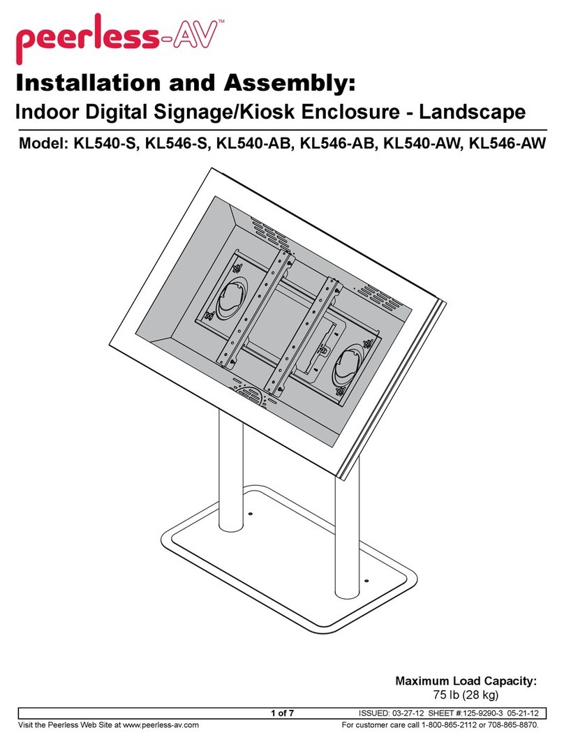
peerless-AV KL540-S Guide

peerless-AV
peerless-AV KIP640 User manual

peerless-AV
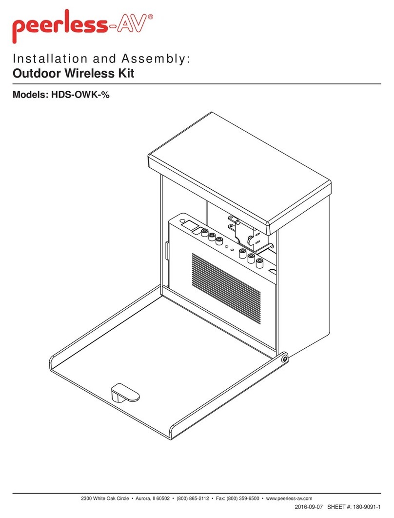
peerless-AV HDS-OWK Series Guide

peerless-AV
peerless-AV KL546-TOSHIBA02 Guide

peerless-AV
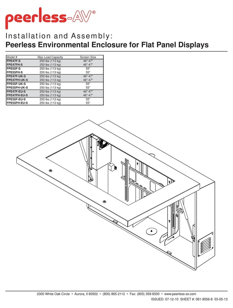
peerless-AV FPE47F-S Guide

peerless-AV
peerless-AV KIL655-S-EUK User manual

peerless-AV
peerless-AV CL-ENCL68 User manual

peerless-AV
peerless-AV KIP640-S User manual

peerless-AV
peerless-AV KIL640 User manual