Pegasus PS1133 User manual

www.Pegasustech.net
PS1133 Barcode Scanner
User Manual

www.Pegasustech.net

www.Pegasustech.net
NOTICE
Ensure that the optional DC adapter works at +5 VDC, especially for the RS-232 interface
cable.
1. All software, including firmware, furnished to the user is on a licensed basis.
2. The right is reserved to make changes to any software or product to improve reliability, function, or
design.
3. The material in this manual is subject to change without notice. Please go to www.pegasustech.net
for latest service information.
4. A standard packing includes a scanner, a PS2 cable and a CD (or a user manual). Accessories
include a stand, a RS-232 cable, a 5 VDC adaptor and a USB cable.
i

www.Pegasustech.net
ii

www.Pegasustech.net
Contents
NOTICE.......................................................................................................................................................i
Contents...................................................................................................................................................iii
1 Specifications........................................................................................................................................1
1-1 Technical specifications ...................................................................................................................1
1-2 Default setting for each barcode......................................................................................................1
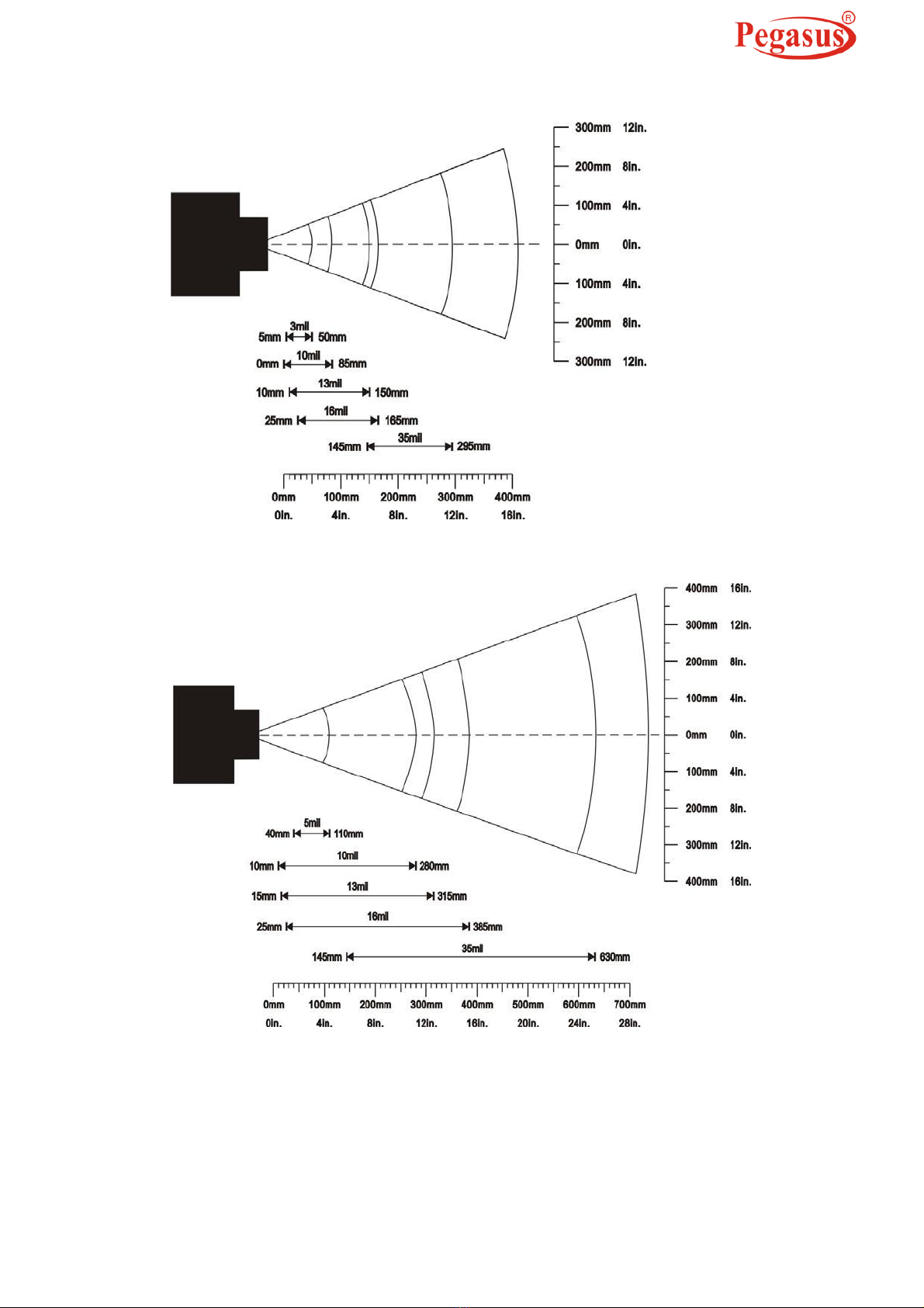
1-3 Decode zone ....................................................................................................................................2
2 Get Started.............................................................................................................................................3
2-1 Cable connector pin-outs descriptions.............................................................................................3
2-2 Dimensions.......................................................................................................................................4
2-3 Parts of the scanner .........................................................................................................................5
2-4 Introduction to installation.................................................................................................................6
2-4-1 Installation - keyboard wedge............................................................................................6
2-4-2 Installation - RS-232...........................................................................................................6
2-4-3 Installation - USB ...............................................................................................................7
2-4-5 Remove the interface cable...............................................................................................7
2-5 Scanning...........................................................................................................................................8
2-6 Auto-detection ..................................................................................................................................8
3 Parameter menus..................................................................................................................................9
3-1 Example: configure scanner.............................................................................................................9
3-2 Operate the scanner by receiving command via UART.................................................................11
3-3 Interface selection ..........................................................................................................................12
3-4 Keyboard wedge interface..............................................................................................................13
3-5 RS-232 interface.............................................................................................................................17
3-6 USB interface .................................................................................................................................20
3-7 Scan mode & some global settings................................................................................................23
3-8 Indication ........................................................................................................................................27
3-9 Auto-detection setting.....................................................................................................................28
3-10 UPC-A...........................................................................................................................................29
3-11 UPC-E...........................................................................................................................................31
3-12 UPC-E1.........................................................................................................................................33
3-13 EAN-13 (ISBN/ISSN)....................................................................................................................35
3-14 EAN-8...........................................................................................................................................38
3-15 Code 39 (Code 32, Trioptic Code 39) ..........................................................................................40
3-16 Interleaved 2 of 5..........................................................................................................................43
3-17 Industrial 2 of 5 (Discrete 2 of 5)..................................................................................................45
3-18 Matrix 2 of 5..................................................................................................................................46
3-19 Codabar........................................................................................................................................48
3-20 Code 128......................................................................................................................................51
3-21 UCC/EAN 128 ..............................................................................................................................53
3-22 ISBT 128.......................................................................................................................................55
3-23 Code 93........................................................................................................................................57
3-24 Code 11........................................................................................................................................59
3-25 MSI/Plessey..................................................................................................................................61
3-26 UK/Plessey...................................................................................................................................63
3-27 China Post....................................................................................................................................65
3-28 China Finance ..............................................................................................................................67
3-29 Telepen.........................................................................................................................................70
3-30 GS1 DataBar (GS1 DataBar Truncated)......................................................................................72
3-31 GS1 DataBar Limited ...................................................................................................................73
3-32 GS1 DataBar Expanded...............................................................................................................74
3-33 G1-G4 & C1-C2 & FN1 substitution string setting........................................................................76
3-34 G1-G4 string position & Code ID position....................................................................................80
3-35 String transmission.......................................................................................................................81
4 Troubleshooting..................................................................................................................................84
5 Maintenance.........................................................................................................................................85
6 Assembling the stand.........................................................................................................................86
iii

www.Pegasustech.net
7 Barcode representing non-printable character ...............................................................................87
8 ASCII Table ..........................................................................................................................................88
9 Test Chart.............................................................................................................................................89
10 Return default parameters & Firmware version list ......................................................................91
11 Configuration alphanumeric entry barcode...................................................................................92
iv

www.Pegasustech.net
1 Specifications
1-1 Technical specifications
Table 1-1 Technical specifications
Dimensions
Height × Width × Depth:8.2 cm × 6.7 cm × 16.8 cm
Weight
168 g, without cable
Cable
Straight 2.0 m
Connector Type
RJ-45 phone jack connector
Case Material
PC+TPU
Programming Method
Manual (reading special barcode)
Firmware Upgrade
Online
Indicator
Beeper, LED
Interface Supported
Keyboard wedge, RS-232, USB Keyboard, USB virtual COM
Operating Mode
Hand-held, Auto-detection (optional)
Input Voltage
5 VDC ± 0.25 V
Power
500 mW (operating), 650 mW (maximum)
Current
100 mA (operating), 130 mA (maximum)
Standby Current
<250 μA
Laser
645-660 nm laser diode
Decoding Rate
200 times/sec
Scanning Angle
±60°, ±65°, ±42° (skew, pitch, roll)
Print Contrast
25% minimum reflection difference
UPC-A, UPC-E, UPC-E1, EAN-13, EAN-8, ISBN (Bookland EAN), ISSN, Code
39, Code 39 full ASCII, Code 32, Trioptic Code 39, Interleaved 2 of 5, Industrial 2
Decoding Capability
of 5 (Discrete 2 of 5), Matrix 2 of 5, Codabar (NW7), Code 128, UCC/EAN 128,
ISBT 128, Code 93, Code 11 (USD-8), MSI/Plessey, UK/Plessey, China Post,
China Finance, GS1 DataBar (formerly RSS) variants, Telepen
(1 mil = 0.0254 mm)
Long-Range series
High-Density series
Decoding depth
5 mil: 40-110 mm
3 mil: 5-50 mm
10 mil: 10-280 mm
10 mil: 10-85 mm
& Min. element width
13 mil: 15-315 mm
13 mil: 10-150 mm
16 mil: 25-385 mm
16 mil: 25-165 mm
35 mil: 145-630 mm
35 mil: 145-295 mm
Temperature
0° to 50°C (32° to 120°F), operating; -40° to 60°C (-40° to 140°F), storage
Humidity
5% to 95% (non-condensing)
Laser Safety: EN60825-1, Class 1
EMC: EN55022, EN55024
Safety
Electrical Safety: EN60950-1
Drop resistance: Multiple 4.0 m (13.1 ft.) drops to concrete
Protection class: IP52
1

www.Pegasustech.net
1-2 Default setting for each barcode
Table 1-2 Default setting for each barcode
Code type
Read
Check digit
Check digit
Min. code
Proprietary
AIM
enable
verification
transmission
length
code ID
code ID
UPC-A
√
√
√
(12)
2
A
]Em
UPC-E
√
√
√
(8)
2
D
]Em
UPC-E1
√
√
√
(8)
2
D
]Em
EAN-13
√
√
√
(13)
2
A
]Em
EAN-8
√
√
√
(8)
2
C
]Em
ISBN (Bookland EAN)
√
√
√
(13)
2
B
]Em
/ ISSN
1
Code 39
√
-
-
1
M
]Am
Interleaved 2 of 5
√
-
-
6
I
]Im
Industrial 2 of 5
-
-
-
4
H
]Im
Matrix 2 of 5
√
-
-
6
X
]Im
Codabar
√
-
-
4
N
]Fm
Code 128
√
√
-
1
K
]Cm
UCC/EAN 128
√
√
-
1
K
]Cm
ISBT 128
√
√
-
1
K
]Cm
Code 93
√
√
-
1
L
]Gm
Code 11
-
√
-
4
V
-
MSI/Plessey
-
-
-
4
O
]Mm
UK/Plessey
√
√
-
1
U
]Mm
China Post
√
-
-
(11)
2
T
]Im
China Finance
√
-
-
(10)
2
Y
-
Telepen
√
√
-
1
P
]Em
GS1 DataBar
√
-
-
(16)
2
R
]em
GS1 DataBar Truncated
3
√
-
-
(16)
2
R
]em
GS1 DataBar Limited
√
-
-
(16)
2
R
]em
GS1 DataBar Expanded
√
-
-
1
R
]em
Note: 1The settings for ISBN/ISSN and EAN-13 must be the same except the code ID.
2Fixed-length barcodes.
3The settings for GS1 DataBar Truncated and GS1 DataBar must be the same.
1

www.Pegasustech.net
1-3 Decode zone
Figure 1-1 High-density series
Figure 1-2 Long-range series
2

www.Pegasustech.net
2 Get Started
2-1 Cable connector pin-outs descriptions
Figure 2-1 Cable connector interface pin-outs
The pin-outs descriptions in Table 2-1 apply to the cable connector on the scanner and are for
reference only.
Table 2-1 Cable connector pin-outs descriptions
Pin
RS232
Keyboard (PS2)
USB
1
Power (+5V)
Power (+5V)
Power (+5V)
2
+3.3V ( for interface auto
Ground (for interface auto
+3.3V ( for interface auto
selection purpose)
selection purpose)
selection purpose)
3
Ground
Ground
Ground
4
+3.3V ( for interface auto
Reserved
Ground (for interface auto
selection purpose)
selection purpose)
5
TxD
KeyClock
Reserved
6
RxD
KeyData
Reserved
7
Reserved
TermClock
Reserved
8
Reserved
TermData
Reserved
9
CTS
Reserved
D-
10
RTS
Reserved
D+
Note: Voltage level of all RS232 Pin-outs (RxD, TxD, CTS and RTS) is 0V for logic low and 3.3V for
logic high.
3

www.Pegasustech.net
2-2 Dimensions
Figure 2-2 Dimensions of scanner
4

www.Pegasustech.net
2-3 Parts of the scanner
Figure 2-3
①LED
②Exit window
③Trigger
④Cable interface port
⑤Release-hole of the cable
⑥Beeper
5

www.Pegasustech.net
2-4 Introduction to installation
Note: If any of the below operation is incorrect, turn off the power immediately and check the scanner
for any improper connections. Go through all steps again.
2-4-1 Installation - keyboard wedge
1. Switch off the host and unplug the keyboard connector.
2. Attach the modular connector of the Y-cable to the cable interface port on the scanner.
3. Connect the round male DIN host connector of the Y-cable to the keyboard port on the host device.
4. Connect the round female DIN keyboard connector of the Y-cable to the keyboard.
5. Ensure that all connections are secure.
6. Switch on the host system.
Figure 2-4
2-4-2 Installation - RS-232
1. Connect the RS-232 interface cable to the bottom of the scanner.
2. Connect the other end of the interface cable to the serial port on the host. Tighten the two screws to
secure the connector to the port.
3. If the host does not have power supply (on PIN 9), connect the external power supply (DC adapter)
to the RS-232 cable.
Figure 2-5
6

www.Pegasustech.net
2-4-3 Installation - USB
The scanner attaches directly to a USB host, and is powered by it. No additional power supply is
required.
1. Refer to Figure 7-3, connect the USB interface cable to the bottom of the scanner.
2. Plug the series A connector in the USB host, or an available port of the terminal.
3. Windows will automatically detect the USB device.
Figure 2-6
2-4-5 Remove the interface cable
Figure 2-7
1. Find the release-hole.
2. Insert a thin wire into the hole and pull out the cable gently.
7

www.Pegasustech.net
2-5 Scanning
The scanner has two scanning modes: hand-held and auto-detection. When the scanner is scanning,
ensure the scan line crosses every bar and space of the symbol.
RIGHT
WRONG
Figure 2-8
2-6 Auto-detection
The auto-detection scanning mode has two operating modes: in-stand and always ON. The following is
an introduction to in-stand auto-detection mode.
1. When the scanner is seated in the stand, the scanner operates in auto-detection mode (see Figure
2-9). When scanner is removed from the stand, it operates in its normal hand-held mode.
2. To scan a bar code, present the bar code and ensure the scan line crosses every bar and space of
the symbol.
3. Upon successful decode, the scanner beeps and the LED lights.
4. When the laser light is off, the present bar code must be removed to active next scanning.
Figure 2-9
8

www.Pegasustech.net
3 Parameter menus
3-1 Example: configure scanner
Important notes:
1. After each successful programming, the scanner will beep twice.
2. Throughout the programming barcode menus, the factory default settings are indicated with
asterisks (*).
3. During the process of programming, LED is lighting to indicate the programming correctness. LED
will go off if any incorrect programming operation performed.
4. After each successful programming, LED will go off and the scanner will beep twice.
Two programming modes have been provided as bellows:
❶Single-scan setting
Scan the appropriate Single-scan setting (e.g. %0101D00%) according to the user’s demand.
Example: to set Flow control to be XON/XOFF.
Steps: Scan the following barcode.
❷Multiple-scan setting
The steps of configure scanner are:
1. Scan the SETUP bar code on the parameter setting part.
2. Enter the option mode by scanning the Option bar code.
3. To the right of the option barcode, the necessary alphanumeric inputs are listed. Scan these
alphanumeric entries.
4. Scan the END bar code, listed on the lower right hand corner of each parameter setting part.
5. Notes that only one parameter can be setup at each time.
Example: to set Flow control to be XON/XOFF.
Steps: Scan the following barcodes in order.
SETUP bar code
SETUP
Single-scan setting
Option bar code
Option
Alpha. entry
Single-scan setting
Flow control
None
00*
RTS/CTS
01
(Host: Low RTS)
9

www.Pegasustech.net
RTS/CTS
02
(Host: High RTS)
XON/XOFF
03
ACK/NAK
04
Inter-character delay
0ms
00*
5ms
01
END
Option bar code
END bar code
Alpha. entries
10

www.Pegasustech.net
3-2 Operate the scanner by receiving command via UART
Note
1) The information in this chapter is provided for the scanner with RS232 cable or USB cable.
2) If the scanner is with USB cable, the setting of USB device type must be set as “USB virtual COM”.
Please refer to chapter of 3-6 USB interface.
3) Please read the chapter of 3-7 Scan mode & some global settings about the setting of Scan mode
in details.
4) UART parameter setting:
a) Baud rate: 9600 bps.
b) Data bits: 8 bits.
c) Stop bit: 1 bit.
d) Parity check bit: None.
e) Flow control: None.
Guide of control command: all commands are sent by UART
1) Start command: “0x54” (T)
When the scanner received the above command, it will start barcode scanning following the setting
of Scanning mode. If the scanner is in the mode of “Auto-detection”, the scanner will have a single
scan, then returns to “Auto-detection” mode.
2) Stop command: “0x50” (P)
If the Scanning mode is set as “Alternate continue” or “Continue”, and the scanner received the
above command, it will stop barcode scanning and act as in an idle mode.
3) Restart command: “0x35” (R)
Once the scanner received the above command, it will restart.
Returning message from the scanner
1) A successful decode
Once the scanner successfully decoded a barcode, the scanner will stop scanning and returns the
barcode data to the Host.
2) Not a successful decode
Once the scanner failed to decode a barcode before stopping scanning, the scanner will return a
message to the Host. The message is set as “0x25, 0x25, 0x4E, 0x6F, 0x52, 0x65, 0x61, 0x64”
(%%NoRead).
11

www.Pegasustech.net
3-3 Interface selection
This scanner supports interfaces such as keyboard wedge, RS-232 serial wedge, and USB interface. In
most of the cases, simply selecting an appropriate cable provided by the manufacturer will work for a
specific interface.
Interface selection:
Auto detection -By setting this function, the scanner will automatically detect the keyboard wedge,
RS-232 or USB interface for user.
SETUP
Option bar code
Option
Alpha. entry
Single-scan setting
Auto detection
00*
(Keyboard wedge /RS-232/USB)
Interface selection
Keyboard wedge
01
RS-232
02
USB
03
END
12

www.Pegasustech.net
3-4 Keyboard wedge interface
Keyboard type: As a keyboard interface, the scanner supports most of the popular PCs and IBM
terminals.
Keyboard layout: The scanner supports different national keyboard layouts.
Clock period: According to the PS2 protocol, the clock is provided by the device, e.g. keyboard or
scanner, with the period between 60us to 100us.
Delay-after-compound-key: In some rare occasions, machine with low speed PS2 communication
port would require a free time gap following the press/release of the compound key (Shift, Ctrl or Alt).
Numeric key:
Alphabetic key- the scanner will output code result as alphabetic key.
Numeric key- the scanner will output code result as pressing numeric keypad ( ‘0’, ‘1’, ‘2’, ‘3’, ‘4’, ‘5’,
‘6’, ‘7’, ‘8’, ‘9’, ‘.’, ‘+’, ‘-‘, ‘/’, ‘*’ only).
Alt+ keypad- the scanner will output code result as pressing Alt+ numeric key (on keypad). Note that
the Num Lock control key must be ON. This setting can be specially adapted for use with different
national keyboard layout.
Power-on simulation: All of the PCs check the keyboard status during power-on self test. It simulates
keyboard timing and passes keyboard present status to the PC during power-on.
Inter-character delay: This delay is inserted after each data character transmitted.
Inter-byte delay: This delay is inserted after each byte transmitted. Normally a character is comprised
of three or above bytes.
Block trans. delay: It is a delay timer between barcode data output. This feature is used to transfer
continually with shorter barcode data.
Caps Lock reversion: By setting enable, the status of Caps Lock key (i.e. being pressed ON or OFF)
on the keyboard is simulated in a reversion status.
Caps Lock override: If this function is enabled, on AT or AT notebook hosts, the keyboard ignores the
state of the Caps Lock key. Therefore, an ‘A’ in the bar code is sent as an ‘A’ no matter what the state
of the keyboard’s Caps Lock key.
A guide of setting while the scanned data is incorrectly displayed on the host
If some characters are missed or some additional characters are incorrectly displayed on the host,
set the Inter-byte delay (0208) to be “01” or greater value.
If some capital character (e.g. “A”) or compound-key-characters (e.g.“shift+”, “Ctrl+”,
“Alt+”) are displayed incorrectly, set the Delay-after-compound-key to be “01” or greater value.
If some digits are incorrectly displayed as some symbol characters (e.g. “1” and “2” are displayed
incorrectly as “!” and “@”), set the Clock period (0203) to be greater value (e.g. 04, 05).
13
Table of contents
Other Pegasus Barcode Reader manuals