PEHA 293/2 User manual

291 Z (Rev01_080728) D - 1
Paul Hochköpper GmbH & Co. KG
Postfach 1727 • D-58467 Lüdenscheid • Tel.: +49 (0)2351 185-0 • Fax: +49 (0)2351 27666 • e-mail: [email protected] • Internet: www.peha.de
31060000-143
Installations- und Bedienungsanleitung
Oberteil Zeitschaltuhr
für UP Relaiseinsatz 293/2 und 293/6
Art.Nr.: 291 Z
D
1. Allgemeines
1.1 Verwendung
Die Zeitschaltuhr (291 Z) wird in Kombination mit dem
Relaiseinsatz 293/2 und 293/6 verwendet. Mit der
Zeitschaltuhr können Verbraucher automatisch durch
Schaltzeiten oder manuell ein-/ ausgeschaltet werden.
Zusätzlich ist eine Schaltfunktion über die Nebenstellen
der Relaiseinsätze möglich.
– Manuell bedienbar
– Minimale Schaltzeit 1 Minute
– Tages-/Wochenprogrammierung
– 24 Schaltzeiten programmierbar
– 30 Minuten Netzpuffer bei Spannungsausfall,
die Programmierung bleibt erhalten.
Hinweis: Vor Inbetriebnahme Bedienungsanleitung sorg-
fältig durchlesen.
1.2 Garantiebestimmungen
Diese Bedienungsanleitung ist Bestandteil des Gerätes
und der Garantiebedingungen. Sie ist dem Benutzer zu
überreichen. Die technische Bauart der Geräte kann sich
ohne vorherige Ankündigung ändern. PEHA Produkte
sind mit modernsten Technologien nach geltenden nati-
onalen und internationalen Vorschriften hergestellt und
qualitätsgeprüft. Sollte sich dennoch ein Mangel zeigen,
übernimmt PEHA, unbeschadet der Ansprüche des End-
verbrauchers aus dem Kaufvertrag gegenüber seinem
Händler, die Mängelbeseitigung wie folgt:
Im Falle eines berechtigten und ordnungsgemäß geltend
gemachten Anspruchs wird PEHA nach eigener Wahl den
Mangel des Gerätes beseitigen oder ein mangelfreies
Gerät liefern. Weitergehende Ansprüche und Ersatz von
Folgeschäden sind ausgeschlossen. Ein berechtigter
Mangel liegt dann vor, wenn das Gerät bei Übergabe an
den Endverbraucher durch einen Konstruktions-, Ferti-
gungs- oder Materialfehler unbrauchbar oder in seiner
Brauchbarkeit erheblich beeinträchtigt ist. Die Gewähr-
leistung entfällt bei natürlichem Verschleiß, unsachge-
mäßer Verwendung, Falschanschluss, Eingriff ins Gerät
oder äußerer Einwirkung. Die Anspruchsfrist beträgt 24
Monate ab Kauf des Gerätes durch den Endverbraucher
bei einem Händler und endet spätestens 36 Monate
nach Herstellung des Gerätes. Für die Abwicklung von
Gewährleistungsansprüchen gilt Deutsches Recht.
1.3 Entsorgung des Gerätes
Zur Entsorgung des Gerätes sind die Gesetze und Nor-
men des Landes einzuhalten, in dem das Gerät betrie-
ben wird!
2. Sicherheit
Das Gerät ist nur für die bestimmungsgemäße Verwen-
dung vorgesehen. Ein eigenmächtiger Umbau oder eine
Veränderung ist verboten! Es darf nicht in Verbindung
mit anderen Geräten verwendet werden, durch deren
Betrieb Gefahren für Menschen, Tiere oder Sachwerte
entstehen können.
Folgende Punkte sind zu berücksichtigen:.
• Die Bedienungsanleitung des Gerätes und
der Relaiseinsätze.
• Eine Bedienungsanleitung kann nur allgemeine Be-
stimmungen anführen. Diese sind im Zusammenhang
mit einer spezifischen Anlage zu sehen.
3. Technische Daten
4. Aufbau und Beschreibung
4.1 Ansicht und Zubehör
4.2 Anzeige und Bedienungstasten
5. Installation und Inbetriebnahme
5.1 Wichtige Installationshinweise !!
– Zeitschaltuhr nur bei ausgeschalteter Spannungsver-
sorgung aus Steckerbuchse entfernen oder einstecken.
– Nur in geschlossenen Räumen
verwenden
.
5.2 Installation
• Montage und Installation des Relaiseinsatzes nach
Anleitung vornehmen (nur Elektrofachkraft).
• Zeitschaltuhr vorsichtig in Steckerbuchse einstecken.
5.3 Inbetriebnahme
• Nach Installation Elektrische Anlage einschalten.
• Grundeinstellung vornehmen (s. Punkt 6.1).
• Schaltzeiten programmieren (s. Punkt 6.2).
Artikelnummer 291 Z
Einbauhöhe 0,8 – 1,5 m
Minimale Umschaltzeit 1 Minute
Umgebungstemperatur 0° bis + 40qC
Lagertemperatur - 25° bis + 75°C
Kennzeichnung CE
Schutzart IP20
6. Funktionen
6.1 Grundeinstellungen
Bei der ersten Inbetriebnahme oder nach einem RESET
muss die Grundeinstellung vorgenommen werden.
Schritt 1: Anzahl der Ausgänge einstellen
Die Zeitschaltuhr wird in Kombination mit dem Relaisein-
satz 293/6 (1 Ausgang) oder 293/2 (2 Ausgänge) verwen-
det. Daher ist die Anzahl der zu verwendenden Ausgänge
einzustellen.
Die Einstellung bleibt auch bei Spannungsausfall erhal-
ten und muss nur einmal vorgenommen werden.
Hinweis:
Die Einstellung wird bei der ersten Inbetrieb-
nahme automatisch aktiviert.
Schritt 2: Uhrzeit und Wochentag einstellen
Hinweise:
– Ist keine Uhrzeit gespeichert, wird die Einstellung der
Uhrzeit und des Wochentags automatisch aktiviert.
– Ohne die Betätigung einer Taste, kehrt das Gerät
nach 30s automatisch zur Grundanzeige zurück.
Einstellung beenden
drücken
kurz drücken
CH:02 = 2 Ausgänge
CH:01 = 1 Ausgang
p
p
Anzahl der Ausgänge
einstellen
CH:01
Uhrzeit blinkt
ca. 3s betätigen 1
00:00
1
15:45
Uhrzeit einstellen
kurz drücken:
Minuten einstellen
lang drücken:
Stunden einstellen
p
p
1 2 3 4 5 6 7
15:45
Wochentag einstellen
drücken
1 = Mo, 2 = Di, 3 = Mi,
4 = Do, 5 = Fr ...........
day
Einstellung beenden
drücken
00:00
C1 C2
1
Ausgang 1 ein-/ ausschalten
Ausgang 2 ein-/ ausschalten
Wochenblock / Wochentag auswählen
Programmiermodus aktivieren
Ausgang / Ausgänge einstellen
Uhrzeit und Wochentag einstellen
Rückstelltaste (RESET)
Hinweis: Die Tasten day und prg werden nur bei der
ersten Inbetriebnahme oder der Programmierung der
Zeitschaltuhr verwendet.
p
p
day
prg
ch
-ENà
0ROGRAMMIERUNG
!NGABE DES !USGANGSKANALS
-ANUELLE"EDIENUN
G
-ENà
:EITEINSTELLUNG
Anzeige Ausgang 1 u. 2
(EIN/AUS, automatisch)
.POUBH
4QFJDIFSQMBU[
293/2
230V~/µ4A 50Hz
L
1
08:15
�
�
day
prg ch
293/6
230V~/µ10A 50Hz
Zeitschaltuhr
(291 Z)
Relaiseinsatz
293/2
Steckerbuchse für Oberteil Steckerbuchse für Oberteil
Relaiseinsatz
293/6

291 Z (Rev01_080728) D - 2
Paul Hochköpper GmbH & Co. KG
Postfach 1727 • D-58467 Lüdenscheid • Tel.: +49 (0)2351 185-0 • Fax: +49 (0)2351 27666 • e-mail: [email protected] • Internet: www.peha.de
31060000-143
6.2 Schaltzeiten programmieren
Das Gerät kann
Verbraucher automatisch durch
Schalt-
zeiten
ein-/ausschalten.
24 Schaltzeiten sind program-
mierbar (
01 bis 24)
.
Zusätzlich ist der Wochentag oder Wochenblock und der
Schaltzustand der Ausgänge auszuwählen.
a) Schaltzeit hinzufügen
Hinweise:
– Die Einstellung kann jederzeit beendet werden.
– Die Anzahl der noch freien Schaltzeiten wird z.B.
mit rE:21 = 21 restliche Schaltzeiten angezeigt.
– Ohne die Betätigung einer Taste, kehrt das Gerät
nach 30s automatisch zur Grundanzeige zurück.
kurz drücken
gedrückt halten
prg
Werkseinstellungen
CH:01
b) Schaltzeit ändern
Hinweise:
– Die Einstellung kann jederzeit beendet werden.
– Die Anzahl der noch freien Schaltzeiten wird z.B.
mit rE:21 = 21 restliche Schaltzeiten angezeigt.
– Ohne die Betätigung einer Taste, kehrt das Gerät
nach 30s automatisch zur Grundanzeige zurück.
c) Schaltzeit löschen
6.3 Reset-Taste
Zur Behebung eines Störungsfalls kurz auf die RESET-
Taste drücken. Die Programmierung bleibt erhalten.
6.4 Werkseinstellungen aufrufen
Alle vom Benutzer programmierten Einstellungen und
Schaltzeiten werden gelöscht. Achtung! Danach muss
eine neue Grundeinstellung vorgenommen werden !
Danach wird die Einstellung zur Anzahl der Ausgänge
aktiviert (s. Schritt 1 unter Punkt 6.1).
7. Bedienung
Die Bedienung des Relaiseinsatzes erfolgt automatisch
über programmierte Schaltzeiten oder manuell über die
Tasten pund q. Der Relaiseinsatz ist zusätzlich über
zwei Nebenstellen schaltbar.
7.1 Manuelle Bedienung
Eine manuelle Bedienung kann jederzeit erfolgen.
Dabei blinkt das Handsymbol „manuelle Bedienung“
und der zugehörige Ausgang (C1, C2).
7.2 Automatik AUS / EIN
Der automatische Betrieb mit programmierten Schalt-
zeiten kann ein-/ oder ausgeschaltet werden.
Anzeigen automatischer / manueller Betrieb:
7.3 Funktion der Nebenstellen (Relaiseinsatz)
Externe Taster an den Nebenstelleneingang E1 und
E2 des Relaiseinsatzes haben die folgende Funktion:
8. Störungsdiagnose- /behebung
8.1 Neuanlage oder vorhandene Anlage
• Sicherungsautomat und Spannungsversorgung
prüfen (nur Elektrofachkraft).
• Angeschlossenen Verbraucher und Anschluss-
leitungen prüfen (nur Elektrofachkraft).
8.2 Kontakt
Telefon:.................... +49 (0)2351 185-0
Telefax:..................... +49 (0)2351 27666
Internet:.................... www.peha.de/contact.aspx
E-Mail:...................... [email protected]
Zeitschaltuhr Funktion
Taste pkurz drücken Ausgang 1 EIN/AUS
Taste qkurz drücken Ausgang 2 EIN/AUS
Zeitschaltuhr
Funktion
Taste p,qlange
(ca. 3s) drücken
Automatik AUS
Ausgang dauerhaft
EIN/AUS
Taste p,q
kurz drücken
Automatik EIN
Ausgang EIN/AUS
Relaiseinsatz Funktion
Taster (E1) kurz drücken Ausgang 1 EIN/AUS
Taster (E1) lange
(ca. 3s) drücken
Ausgang 1 EIN/AUS
(ohne Automatik)
Taster (E2) kurz drücken Ausgang 2 EIN/AUS
Taster (E2) lange
(ca. 3s) drücken
Ausgang 2 EIN/AUS
(ohne Automatik)
Einstellung beenden
drücken
16:10
prg
C1 C2
1
Wochenblock oder
Wochentag einstellen
kurz drücken
day
Schaltzeit einstellen
kurz drücken:
Minuten einstellen
lang drücken:
Stunden einstellen
p
p
drücken
ch
Ausgänge aktivieren
21:30 Prog.
1 2 3 4 5
02 C1 C2
21:30 Prog.
1 2 3 4 5
02 C1 C2
22:00 Prog.
1 2 3 4 5
02 C1 C2
kurz drücken
(01 ...24)
Schaltzeit auswählen
prg 22:00 Prog.
1 2 3 4 5 6 7
02 C1 C2
Programmiermodus
(Anzeige blinkt)
ca. 3s drücken 07:45 Prog.
1 2 3 4 5
01 C1 C2
Einstellung beenden
drücken
16:05
prg
C1 C2
1
Wochenblock oder
Wochentag einstellen
kurz drücken
day
Schaltzeit einstellen
kurz drücken:
Minuten einstellen
lang drücken:
Stunden einstellen
p
p
drücken
ch
Ausgänge aktivieren
07:45 Prog.
1 2 3 4 5
01 C1 C2
07:45 Prog.
1 2 3 4 5
01 C1 C2
--:--
Prog.
1 2 3 4 5
01 C1 C2
kurz drücken
(01 ...24)
Schaltzeit hinzufügen
prg
--:--
Prog.
1 2 3 4 5 6 7
02 C1 C2
Programmiermodus
(Anzeige blinkt)
ca. 3s drücken
--:--
Prog.
1 2 3 4 5 6 7
01 C1 C2
Einstellung beenden
drücken
Programmiermodus
(Anzeige blinkt)
ca. 3s drücken
16:20
prg
C1 C2
1
kurz drücken
(01 ...24)
Schaltzeit auswählen
prg 22:00 Prog.
1 2 3 4 5 6 7
03 C1 C2
07:45 Prog.
1 2 3 4 5
01 C1 C2
Schaltzeit löschen
gleichzeitig
drücken
p
p
--:--
Prog.
1 2 3 4 5 6 7
03 C1 C2
Wochentag
Mo = 1, Di = 2, Mi = 3, Do = 4, Fr = 5, Sa = 6, So = 7
Wochenblock
Mo - So (ganze Woche)
a1 2 3 4 5 6 7
Mo - Sa (lange Arbeitswoche) a1 2 3 4 5 6
Mo - Fr (kurze Arbeitswoche) a1 2 3 4 5
Fr - So (langes Wochenende) a5 6 7
Sa - So (kurzes Wochenende) a6 7
Schaltzustand der Ausgänge C1 und C2
Bei Verwendung des Relaiseinsatzes 293/2 (2 Aus-
gänge) ergeben sich die folgenden Schaltzustände
in der Reihenfolge:
C1 O = AUS C2 O = AUS
C1 O = EIN C2 O = AUS
C1 O = AUS C2 O = EIN
C1 O = EIN C2 O = EIN
C1 O = AUS —
C1 O = EIN —
— C2 O = AUS
— C2 O = EIN
Schaltzustand des Ausgangs C1
Bei Verwendung des Relaiseinsatzes 293/6 (1 Aus-
gang) ergeben sich die folgenden Schaltzustände in
der Reihenfolge:
C1 O = AUS
C1 O = EIN
Betriebsmodus Symbole
Automatik
EIN
C1/C2 aAUS
C1/C2 aEIN
Automatik
AUS + manuell
C1/C2 aDauerhaft AUS
C1/C2 aDauerhaft EIN
Automatik
EIN + manuell
C1/C2 + blinken aAUS
C1/C2 + blinken aEIN

291 Z (Rev01_080728) GB - 1
Paul Hochköpper GmbH & Co. KG
Postfach 1727 • D-58467 Lüdenscheid • Tel.: +49 (0)2351 185-0 • Fax: +49 (0)2351 27666 • e-mail: [email protected] • Internet: www.peha.de
31060000-143
Installation and operating instructions
Upper section Timer
for FM relay inset 293/2 and 293/6
Art. No.: 291 Z
GB
1. General
1.1 Application
The timer (291 Z) is used in combination with relay in-
set 293/2 and 293/6. The timer can be used to switch
consumers on/off automatically at programmed times or
manually. It can also be switched using two relay inset
remote stations.
– Manual operation
– Minimum switching time 1 minute
– Day/Week programming
– 24 programmable switch times
– 30 minutes reserve power in case of power failure,
no loss of programming.
Note: Read through the operating instructions carefully
before putting the device into service.
1.2 Warranty conditions
These operating instructions are an integral part of both
the device and our terms of warranty. They must be
handed over to the user. The technical design of the
device is subject to change without prior notification.
PEHA products are manufactured and quality-checked
using the latest technology and according to applicable
national and international regulations. Nevertheless, if a
product should exhibit a defect, PEHA warrants to make
remedy as follows (regardless of any claims against the
dealer to which the end-user may be entitled as a result
of the sales transaction):
In the event of a justified and properly-established claim,
PEHA shall exercise its prerogative to either repair or
replace the defective device. Further claims or liability
for consequential damage are explicitly excluded. A jus-
tifiable deficiency is one in which the device exhibits a
structural, manufacturing, or material defect that makes
it unusable or substantially impairs its utility at the time
it is turned over to the end-user. The warranty does
not apply to natural wear, unintended usage, incorrect
connection, device tampering or the effects of external
influences. The warranty period is for 24 months from
the date of purchase by the end-user from a dealer and
ends not later than 36 months after the device’s date
of manufacture. German law shall be applicable for the
settlement of warranty claims.
1.3 Disposal of the device
The device must be disposed of in compliance with the
laws and standards of the country in which it is ope-
rated!
2. Safety
This device is only intended to be used for its stated
application. Unauthorised conversions, modifications or
changes are not permissible! This device may not be
used in conjunction with other devices whose operation
could present a hazard to persons, animals or property.
The following must be observed:
• The operating instructions for the device and the relay
insets.
• Operating instructions can only cite general stipula-
tions. These are to be viewed in the context of a spe-
cific system.
3. Technical specifications
4. Structure and description
4.1 View and accessories
4.2 Display and operating buttons
5. Installation and commissioning
5.1 Important installation information!!
– Only remove or plug the timer into the jack when the
power is turned off.
– Only use indoors.
5.2 Installation
• Assemble and install the relay inset in accordance
with the instructions (should only be performed by a
qualified electrician).
• Carefully plug the timer into the jack.
5.3 Start-up
• Switch on the power supply following installation.
• Programme the basic setting (see 6.1).
• Programme the switch times (see 6.2).
293/2
230V~/µ4A 50Hz
L
1
08:15
�
�
day
prg ch
293/6
230V~/µ10A 50Hz
Timer
(291 Z)
Relay inset
293/2
Jack for upper section Jack for upper section
Relay inset
293/6
Art. no. 291 Z
Installation height 0,8 – 1,5 m
Minimum transit time 1 minute
Ambient temperature 0° to + 40qC
Storage temperature - 25° to + 75°C
Identification CE
Type of protection IP20
Complete setting
press
press briefly
CH:02 = 2 outputs
CH:01 = 1 output
p
p
Set the number
of outputs
CH:01
Time flashes
press for about 3s 1
00:00
1
15:45
Set the time
press briefly:
Set the minutes
press longer:
Set the hours
p
p
1 2 3 4 5 6 7
15:45
Set the day of the week
press
1 = Mon, 2 = Tues, 3 = Wed,
4 = Thur, 5 = Fri ...........
day
Complete setting
press
00:00
C1 C2
1
6. Functions
6.1 Basic settings
The basic setting must be programmed prior to first use
or following a reset.
Step 1: Set the number of outputs
The timer is used in combination with relay inset 293/6
(1 output) or 293/2 (2 outputs). The number of outputs
to be used must be set.
The setting is maintained in case of a power outage and
only needs to be programmed once.
Note: The setting is activated automatically when the
system is commissioned for the first time.
Step 2: Set time and day
Notes:
– The setting for time and day of the week is activated
automatically if no time is stored.
– The device returns automatically to basic display if no
buttons are pressed for 30s.
Switch output 1 on/off
Switch output 2 on/off
Select part of week / day
Activate programming mode
Set output / outputs
Set time and day
Reset
Note:
The day and prg buttons are only used when the timer
is commissioned for the first time or programmed.
p
p
day
prg
ch
-ENà
0ROGRAMMIERUNG
!NGABE DES !USGANGSKANALS
-ANUELLE"EDIENUN
G
-ENà
:EITEINSTELLUNG
Anzeige Ausgang 1 u. 2
(EIN/AUS, automatisch)
.POUBH
4QFJDIFSQMBU[
Manual operation
1 = Monday
Display output channel
(ON/OFF and automatic)
Menu
programming
Memory
capacity
Menu
time setting

291 Z (Rev01_080728) GB - 2
Paul Hochköpper GmbH & Co. KG
Postfach 1727 • D-58467 Lüdenscheid • Tel.: +49 (0)2351 185-0 • Fax: +49 (0)2351 27666 • e-mail: [email protected] • Internet: www.peha.de
31060000-143
6.2 Programming the switching times
The device can switch consumers on/off at programmed
times. 24 switch times can be programmed (01 - 24).
The day or part of the week and the switching state of the
outputs must also be selected.
a) Adding a new switch time
Notes:
– The setting can be interrupted at any time.
– The number of remaining free switch times is dis-
played, e.g. rE: 21 = 21 switch times remaining.
– The device returns automatically to basic display if no
buttons are pressed for 30s.
b) Changing a switch time
Notes:
– The setting can be interrupted at any time.
– The number of remaining free switch times is dis-
played, e.g. rE: 21 = 21 switch times remaining.
– The device returns automatically to basic display if
no buttons are pressed for 30s.
c) Deleting a switch time
6.3 Reset button
In case of malfunction, press the RESET button briefly.
Programmed settings are maintained.
6.4 Call up factory settings
All of the settings and switch times programmed by the
user will be deleted. Caution! A new basic setting must
then be programmed!
The setting for the number of outputs is then activated
(see Step 1, 6.1)
7. Operation
The relay inset is operated automatically using pro-
grammed switch times or manually using the pand q
buttons. The relay inset can also be switched from two
remote stations.
7.1 Manual operation
The system can be operated manually at any time. The
hand symbol “manual operation” and the relevant out-
put (C1, C2) flash.
7.2 Automatic OFF / ON
Automatic operation using programmed switch times
can be switched on or off.
Displaying automatic / manual operation:
7.3 Remote station operation (relay inset)
The external buttons on remote station inputs E1 and
E2 on the relay inset perform the following functions:
8. Troubleshooting & remedies
8.1 New system or existing system
• Check circuit breaker and voltage supply (qualified
electrician only).
• Check connected electrical loads and connection
cables (qualified electrician only).
8.2 Contact
Telephone:................ +49 (0)2351 185-0
Fax:.......................... +49 (0)2351 27666
Internet:.................... www.peha.de/contact.aspx
E-Mail:...................... [email protected]
Operating mode
Symbole
Automatic
ON
C1/C2 aOFF
C1/C2 aON
Automatic
OFF + manual
C1/C2 apermanently OFF
C1/C2 apermanently ON
Automatic
ON + manual
C1/C2 + flashing aOFF
C1/C2 + flashing aON
Complete setting
press
16:05
prg
C1 C2
1
Set the part of the
week or day
press briefly
day
Set the switch time
press briefly:
Set the minutes
press longer:
Set the hours
p
p
press
ch
Activate outputs
07:45 Prog.
1 2 3 4 5
01 C1 C2
07:45 Prog.
1 2 3 4 5
01 C1 C2
--:--
Prog.
1 2 3 4 5
01 C1 C2
press briefly
(01 ...24)
Add a new switch time
prg
--:--
Prog.
1 2 3 4 5 6 7
02 C1 C2
Programming mode
(Display flashes)
press for about 3s
--:--
Prog.
1 2 3 4 5 6 7
01 C1 C2
Day of the week
Mon=1,Tues= 2,Wed=3,Thur =4, Fri=5, Sat=6, Sun=7
Part of week
Mon - Sun (full week)
a1 2 3 4 5 6 7
Mon - Sat (long working week) a1 2 3 4 5 6
Mon - Fri (short working week) a1 2 3 4 5
Fri - Sun (long weekend) a5 6 7
Sat - Sun (short weekend) a6 7
Switching state of outputs C1 and C2
When using the relay inset 293/2 (2 outputs), the
following switching states apply in the following se-
quence:
C1 O = OFF C2 O = OFF
C1 O = ON C2 O = OFF
C1 O = OFF C2 O = ON
C1 O = ON C2 O = ON
C1 O = OFF —
C1 O = ON —
— C2 O = OFF
— C2 O = ON
Switching state of output C1
When using the relay inset 293/6 (1 output), the
following switching states apply in the following se-
quence:
C1 O = OFF
C1 O = ON Complete setting
press
16:10
prg
C1 C2
1
Set the part of the week
or day
press briefly
day
Set the switch time
press briefly:
Set the minutes
press longer:
Set the hours
p
p
press
ch
Activate outputs
21:30 Prog.
1 2 3 4 5
02 C1 C2
21:30 Prog.
1 2 3 4 5
02 C1 C2
22:00 Prog.
1 2 3 4 5
02 C1 C2
press briefly
(01 ...24)
Select switch time
prg 22:00 Prog.
1 2 3 4 5 6 7
02 C1 C2
Programming mode
(Display flashes)
press for about 3s 07:45 Prog.
1 2 3 4 5
01 C1 C2
Complete setting
press
Programming mode
(Display flashes)
press for about 3s
16:20
prg
C1 C2
1
press briefly
(01 ...24)
Select switch time
prg 22:00 Prog.
1 2 3 4 5 6 7
03 C1 C2
07:45 Prog.
1 2 3 4 5
01 C1 C2
Delete switch time
simultaneously
press
p
p
--:--
Prog.
1 2 3 4 5 6 7
03 C1 C2
press briefly
keep pressing
prg
Factory settings
CH:01
Timer Function
Press pbriefly Output 1 ON/OFF
Press qbriefly Output 2 ON/OFF
Timer
Function
Press p,qfor
about 3s
Automatic OFF
Output permanently ON/OFF
Press p,q
briefly
Automatic ON
Output ON/OFF
Relay inset Function
Press (E1) briefly Output 1 ON/OFF
Keep pressing (E1)
(about 3s)
Output 1 ON/OFF
(non-automatic)
Press (E2) briefly Output 2 ON/OFF
Keep pressing (E2)
(about 3s)
Output 2 ON/OFF
(non-automatic)

NL - 1
PEHA Elektro B.V.
Pieter Calandweg 58 • 6827 BK Arnhem • Tel.: +31 (0)26 368 7500 • Fax: +31 (0)26 368 7509 • e-mail: [email protected] • Internet: www.peha-elektro.nl
291 Z (Rev01_080728) 31060000-143
Installatie- en bedieningshandleiding
bovendeel tijdschakelklok voor
inbouw relais inzetmodule 293/2 en 293/6
Art.nr.: 291 Z
NL
1. Algemeen
1.1 Gebruik
De
tijdschakelklok
(291 Z) wordt in combinatie met de
relais inbouwmodule 293/2 en 293/6 gebruikt. Met de
tijdschakelklok kan een verbruiker automatisch door
schakeltijden of handmatig aangestuurd worden. Boven-
dien is een schakelfunctie via 2 externe contacten van
de relais inzetmodule mogelijk.
– Manueel bedienbaar
– Minimale schakeltijd 1 minuut
– Dag-/weekprogrammering
– 24 schakeltijden programmeerbaar
– 30 minuten spanningsbuffer bij spanningsuitval,
de programmering blijft behouden
Aanwijzing: Voor ingebruikname de handleiding zorg-
vuldig doorlezen.
1.2 Garantiebepalingen
Deze handleiding is bestanddeel van het apparaat en de
garantiebepalingen. Deze moet aan de gebruiker over-
handigd worden. De technische bouwwijze van het appa-
raat kan veranderen zonder voorafgaande aankondiging.
PEHA-producten zijn met ultramoderne technologieën
overeenkomstig de van toepassing zijnde nationale en
internationale voorschriften vervaardigd en op kwaliteit
gecontroleerd. Indien desondanks gebreken optreden,
verleent PEHA, ongeacht de claims van de eindverbru-
ikers, uit het koopcontract jegens de handelaar de her-
stelwerkzaamheden als volgt:
In het geval van een terechte en overeenkomstig de
voorschriften ingediende claim zal PEHA naar eigen
keuze het mankement aan het apparaat verhelpen of het
apparaat door een goed werkend exemplaar vervangen.
Verder gaande rechten en de vergoeding van gevolg-
schade zijn uitgesloten. Een reclamatie is terecht, als het
apparaat bij overhandiging aan de eindverbruiker door
een constructie-, fabricage-, of materiaalfout onbruikbaar
of in zijn bruikbaarheid aanzienlijk beperkt is. De garantie
vervalt in het geval van natuurlijke slijtage, onvakkundig
gebruik, verkeerd aansluiten, ingrepen in het apparaat
of externe invloeden. De garantieperiode bedraagt 24
maanden vanaf de aankoop van het apparaat door de
eindverbruiker bij een dealer en eindigt uiterlijk 36 maan-
den na de productie van het apparaat. Voor de afhande-
ling van de garantieclaims geldt het Duitse recht.
1.3 Afvoeren van het apparaat
Voor het afvoeren van het apparaat moeten de wetge-
ving en normen van het land waarin het apparaat ge-
bruikt wordt, worden nageleefd.
2. Veiligheid
Het apparaat is alleen voor de ontworpen doeleinden ge-
schikt. Eigenhandig ombouwen of veranderen is verbo-
den! Het apparaat mag niet in verbinding worden gesteld
met apparaten die door inschakeling gevaar voor men-
sen, dieren of materialen tot gevolg kunnen hebben.
Volgende punten in acht nemen:
• De bedieningshandleiding van het apparaat en van
de relais inbouwmodule.
• Een bedieningshandleiding kan slechts algemene
aanwijzingen aandragen. Deze moeten in samen-
hang met een specifieke installatie worden gezien.
3. Technische gegevens
4. Opbouw en beschrijving
4.1 Aanzicht en toebehoren
4.2 Aanduidingen en bedieningstoetsen
5. Installatie en ingebruikname
5.1 Belangrijke installatieaanwijzingen!!
– Tijdschakelklok alleen bij uitgeschakelde spanning
van de stekkerbus halen of plaatsen.
– Alleen in gesloten ruimten gebruiken.
5.2 Installatie
• Montage en installatie van de relais inbouwmodule
volgens richtlijnen uitvoeren (alleen elektrotechnisch
vakpersoneel).
• Tijdschakelklok voorzichtig op de stekkerbus steken.
5.3 Ingebruikname
• Na installatie de elektrische installatie inschakelen.
• Basisinstellingen programmeren (zie punt 6.1).
Schakeltijden programmeren (zie punt 6.2).
Artikelnummer 291 Z
Inbouwhoogte 0,8 - 1,5 m
Minimale omschakeltijd 1 Minuut
Omgevingstemperatuur 0° tot + 40°C
Opslagtemperatuur - 25° tot + 75°C
Goedkeuringen CE
Veiligheidsklasse IP20
293/2
230V~/µ4A 50Hz
L
1
08:15
�
�
day
prg ch
293/6
230V~/µ10A 50Hz
Timer
(291 Z)
Relais inzet-
module293/2
Stekkerbus voor bovendeel Stekkerbus voor bovendeel
Relais inzet-
module293/6
Uitgang 1 in-/uitschakelen
Uitgang 2 in-/uitschakelen
Weekblok / weekdag kiezen
Programmeermodus activeren
Uitgang / uitgangen instellen
Tijd en weekdag instellen
Herstelknop (RESET)
Aanwijzing: De toetsen day en prg worden slechts
bij eerste ingebruikname of bij programmering van de
tijdschakelklok gebruikt.
p
p
day
prg
ch
-ENà
0ROGRAMMIERUNG
!NGABE DES !USGANGSKANALS
-ANUELLE"EDIENUN
G
-ENà
:EITEINSTELLUNG
Anzeige Ausgang 1 u. 2
(EIN/AUS, automatisch)
.POUBH
4QFJDIFSQMBU[
Handmatige
bediening
1 = maandag
Aanduiding uitgang
(AAN/UIT, automatisch)
Menu
Programmering
Geheugen-
plaats
Menu
Tijdinstelling
6. Functies
6.1 Basisinstellingen
Bij de eerste ingebruikname of na een RESET moet de
basisinstelling uitgevoerd worden.
Stap 1: Aantal uitgangen instellen
De tijdschakelklok wordt in combinatie met de relais in-
zetmodule 293/6 (1 uitgang) of 293/2 (2 uitgangen) ge-
bruikt. Daarom moet het aantal te gebruiken uitgangen
worden ingesteld.
De instelling blijft ook bij spanningsuitval behouden en
hoeft slechts eenmalig te worden geprogrammeerd.
Aanwijzing: Bij de eerste ingebruiksname wordt de in-
stelling automatisch geactiveerd.
Stap 2: Tijd en weekdag instellen
Aanwijzingen:
–
Is er geen tijd ingesteld, wordt de instelling van de
tijd en de weekdag automatisch geactiveerd.
– Als er geen toets wordt ingedrukt, keert het apparaat
naar 30s automatisch naar de basisaanduiding terug.
Instellen beëindigen
Kort drukken:
CH:02 = 2 uitgangen
CH:01 = 1 uitgang
CH:01
p
p
Aantal uitgangen
instellen
Indrukken
Kloktijd knippert
ca. 3s indrukken 1
00:00
1
15:45
Kloktijd instellen
Kort drukken:
Minuten instellen
Lang drukken:
Uren instellen
p
p
1 2 3 4 5 6 7
15:45
Weekdag instellen
Indrukken
1= ma, 2=di, 3=wo,
4=do, 5=vr........
day
Instellen beëindigen
Indrukken
00:00
C1 C2
1

NL - 2
PEHA Elektro B.V.
Pieter Calandweg 58 • 6827 BK Arnhem • Tel.: +31 (0)26 368 7500 • Fax: +31 (0)26 368 7509 • e-mail: [email protected] • Internet: www.peha-elektro.nl
291 Z (Rev01_080728) 31060000-143
6.2 Schakeltijden programmeren
Het apparaat kan verbruikers automatisch middels
schakeltijden in-/uitschakelen. Er zijn 24 schakeltijden
programmeerbaar (01 tot 24).
Bovendien is de weekdag of weekblok en de schakelto-
estand te programmeren.
a) Schakeltijd toevoegen
Aanwijzingen:
– De instelling kan ieder moment beëindigd worden.
– Het aantal nog vrije schakelmomenten wordt bijv. met
rE:21 = 21 resterende schakeltijden aangeduid.
– Als er geen toets wordt ingedrukt, keert het apparaat
naar 30s automatisch naar de basisaanduiding terug.
b) Schakeltijd veranderen
Aanwijzingen:
– De instelling kan ieder moment beëindigd worden.
– Het aantal nog vrije schakelmomenten wordt bijv. met
rE:21 = 21 resterende schakeltijden aangeduid.
– Als er geen toets wordt ingedrukt, keert het apparaat
naar 30s automatisch naar de basisaanduiding terug.
c) Schakeltijd wissen
6.3 Reset toets
Voor het herstellen van een storingsgeval kort op de RE-
SET toets drukken. De programmering blijftbehouden.
Instelling beëindigen
Indrukken
Weekblok of
weekdag instellen
Kort indrukken
day
Schakeltijd instellen
Kort indrukken:
Minuten instellen
Lang indrukken:
Uren instellen
p
p
Indrukken
ch
Uitgang activeren
Kort indrukken
(01..24)
Schakeltijd toevoegen
prg
Programmeermodus
(aanduiding knippert)
ca. 3s indrukken
--:--
Prog.
1 2 3 4 5 6 7
01 C1 C2
--:--
Prog.
1 2 3 4 5 6 7
02 C1 C2
07:45 Prog.
1 2 3 4 5
01 C1 C2
07:45 Prog.
1 2 3 4 5
01 C1 C2
--:--
Prog.
1 2 3 4 5
01 C1 C2
16:05
prg
C1 C2
1
Weekdag
Ma = 1, di = 2, wo = 3, do = 4, vr = 5, za = 6, zo = 7
Weekblok
ma - zo (hele week)
a1 2 3 4 5 6 7
ma - za (lange werkweek) a1 2 3 4 5 6
ma – vr (korte werkweek) a1 2 3 4 5
vr – zo (lang weekend) a5 6 7
za – zo (kort weekend) a6 7
Schakeltoestand van uitgangen C1 en C2
Bij gebruik van de relais inzetmodule 293/2 (2 uit-
gangen) zijn er de volgende schakeltoestanden in
de volgorde:
C1 O = UIT C2 O = UIT
C1 O = AAN C2 O = UIT
C1 O = UIT C2 O = AAN
C1 O = AAN C2 O = AAN
C1 O = UIT —
C1 O = AAN —
— C2 O = UIT
— C2 O = AAN
Schakeltoestand van uitgang C1
Bij gebruik van de relais inbouwmodule 293/6 (1 uit-
gang) zijn er de volgende schakeltoestanden in de
volgorde:
C1 O = UIT
C1 O = AAN
Instelling beëindigen
Indrukken
Programmeermodus
(aanduiding knippert)
ca. 3s indrukken
16:20
prg
C1 C2
1
Kort indrukken
(01..24)
Schakeltijd kiezen
prg 22:00 Prog.
1 2 3 4 5 6 7
03 C1 C2
07:45 Prog.
1 2 3 4 5
01 C1 C2
Schakelmoment wissen
Gelijktijdig
indrukken
p
p
--:--
Prog.
1 2 3 4 5 6 7
03 C1 C2
Instelling beëindigen
Indrukken
16:10
prg
C1 C2
1
Weekblok of
weekdag instellen
Kort indrukken
day
Schakeltijd instellen
Kort indrukken:
Minuten instellen
Lang indrukken:
Uren instellen
p
p
Indrukken
ch
Uitgang activeren
21:30 Prog.
1 2 3 4 5
02 C1 C2
21:30 Prog.
1 2 3 4 5
02 C1 C2
22:00 Prog.
1 2 3 4 5
02 C1 C2
22:00 Prog.
1 2 3 4 5 6 7
02 C1 C2
Programmeermodus
(aanduiding knippert)
ca. 3s indrukken 07:45 Prog.
1 2 3 4 5
01 C1 C2
Kort indrukken
(01..24)
Schakeltijd kiezen
prg
6.4 Fabrieksinstellingen terugzetten
Alle door gebruiker geprogrammeerde instellingen en
schakelmomenten worden gewist. Let op! Hierna moet
een nieuwe basisinstelling uitgevoerd worden!
Hierna word de instelling voor het aantal uitgangen ge-
actieveerd (zie stap 1 onder punt 6.1).
7. Bediening
De bediening van de relais inzetmodule gebeurt automa-
tisch middels de geprogrammeerde schakelmomenten of
manueel met de toetsen penq. Bovendien is de relais
inzetmodule schakelbaar via 2 externe contacten.
7.1 Manuele bediening
Op ieder moment kan een handmatige bediening ged-
aan worden. Hierbij knippert het handsymbool “manue-
le bediening” en de bijbehorende uitgang (C1, C2).
7.2 Automatisch UIT / AAN
Het automatisch bedrijf met geprogrammeerde scha-
kelmomenten kan worden in- of uitgeschakeld.
Aanduiding automatisch / manueel bedrijf:
7.3 Functie externe contacten (relais inzetmodule)
Externe toetsen op de ingangen E1 en E2 van de relais
inzetmodule hebben de volgende functie:
8. Storingsdiagnose- /oplossing
8.1 Nieuwe of bestaande installatie
• Installatieautomaat en voedingsspanning testen
(alleen elektrotechnisch vakpersoneel).
• Aangesloten verbruikers en bekabeling testen
(alleen elektrotechnisch vakpersoneel).
8.2 Contact
Telefoon:.................... +31 (0)26 36 875 00
Fax:............................ +31 (0)26 36 875 09
Internet:...................... www.peha-elektro.nl
Email:......................... [email protected]
Tijdschakelklok Functie
Toets pkort indrukken Uitgang 1 AAN/UIT
Toets qkort indrukken Uitgang 2 AAN/UIT
Relais inbouwmodulemodule
Functie
Toets (E1) kort indrukken Uitgang 1 AAN/UIT
Toets (E1) lang
(ca. 3s) indrukken
Uitgang 1 AAN/UIT
(zonder automaat)
Toets (E2) kort indrukken Uitgang 2 AAN/UIT
Toets (E2) lang
(ca. 3s) indrukken
Uitgang 2 AAN/UIT
(zonder automaat)
Kort indrukken
Ingedrukt houden
prg
Fabrieksinstellingen
CH:01
Tijdschakelklok Functie
Toets
p,q
lang
(ca. 3s) indrukken
Automaat UIT
Uitgang continu AAN/UIT
Toets p,q
kort indrukken
Automaat AAN
Uitgang AAN/UIT
Bedrijfsmodus Symbool
Automaat
AAN
C1/C2 aUIT
C1/C2 aAAN
Automaat
UIT + manueel
C1/C2 aContinu UIT
C1/C2 aContinu AAN
Automaat
AAN + manueel
C1/C2 + knipperen
aUIT
C1/C2 + knipperen
aAAN

291 Z (Rev01_080728) F - 1
Paul Hochköpper GmbH & Co. KG
Postfach 1727 • D-58467 Lüdenscheid • Tel.: +49 (0)2351 185-0 • Fax: +49 (0)2351 27666 • e-mail: [email protected] • Internet: www.peha.de
31060000-143
Notice d’installation et d’utilisation
Partie supérieure composée d’une minuterie
pour les inserts à relais encastrés 293 (2 et 6)
Réf. 291 Z
F
1. Généralités
1.1 Utilisation
La minuterie (291 Z) est utilisée en combinaison avec
les inserts à relais 293/2 et 293/6. La minuterie permet
d’activer ou de désactiver manuellement ou automatique-
ment via des heures d’activation des consommables.
Une fonction de commutation via les postes secondaires
des inserts à relais est, en outre, possible.
– Commande manuelle
– Heure d’activation minimale d’une minute
– Programmation quotidienne/journalière
– 24 heures programmables
– Tampon d’alimentation réseau de 30 mn en cas de
panne de secteur, la programmation est conservée.
Remarque : Lire attentivement la notice d’utilisation
avant la mise en service.
1.2 Clauses de garantie
Cette notice d’utilisation fait partie intégrante de
l’appareil et de nos conditions de garantie. Elle doit être
remise sys-tématiquement à l’utilisateur. Nous nous
réservons le droit de modifier sans préavis la construc-
tion technique des appareils. Les produits PEHA sont
fabriqués et leur qualité est contrôlée en ayant recours
aux technologies ultramodernes et en tenant compte
des directives nationales et internationales en vigueur.
Si toutefois un défaut apparaissait, PEHA s’engage à
remédier au défaut comme suit, sans préjudice des dro-
its du consommateur final résultant du contrat de vente
vis-à-vis de son revendeur:
En cas de l’exercice d’un droit légitime et régulier, PEHA,
à son seul gré, éliminera le défaut de l’appareil ou liv-
rera un appareil sans défaut. Toute revendication allant
au-delà et toute demande de réparation de dommages
consécutifs est exclue. Un défaut légitime existe si
l’appareil est inutilisable au moment de sa livraison au
consommateur final en raison d’un vice de construction,
de fabrication ou de matière ou si son utilisation pratique
est considérablement limitée. La garantie est annulée en
cas d’usure naturelle, d’utilisation incorrecte, de branche-
ment incorrect, d’intervention sur l’appareil ou d’influence
extérieure. La durée de la garantie est de 24 mois à partir
de l’achat de l’appareil par le consommateur final chez un
revendeur et elle prend fin au plus tard 36 mois après la
fabrication de l’appareil. Le droit allemand est applicable
pour le règlement des droits à la garantie.
1.3 Élimination de l’appareil
Pour l’élimination de l’appareil, se conformer à la lé-
gislation et aux normes en vigueur dans le pays où
l’appareil est utilisé.
2. Sécurité
L’appareil est prévu exclusivement pour une utilisation
conforme à sa destination. Toute intervention ou modi-
fication par l’utilisateur est interdite ! Ne pas l’utiliser en
liaison avec d’autres appareils dont le fonctionnement
pourrait mettre en danger les personnes, les animaux
ou les biens.
Tenir compte des points suivants :
• La notice d’utilisation de l’appareil et celle des inserts à
relais.
• Unenoticed’utilisationnepeutdonnerquedesconsignes
denaturegénérale.Ellesdoiventêtreinterprétéesdansle
contexte d’une installation spécifique.
3. Caractéristiques techniques
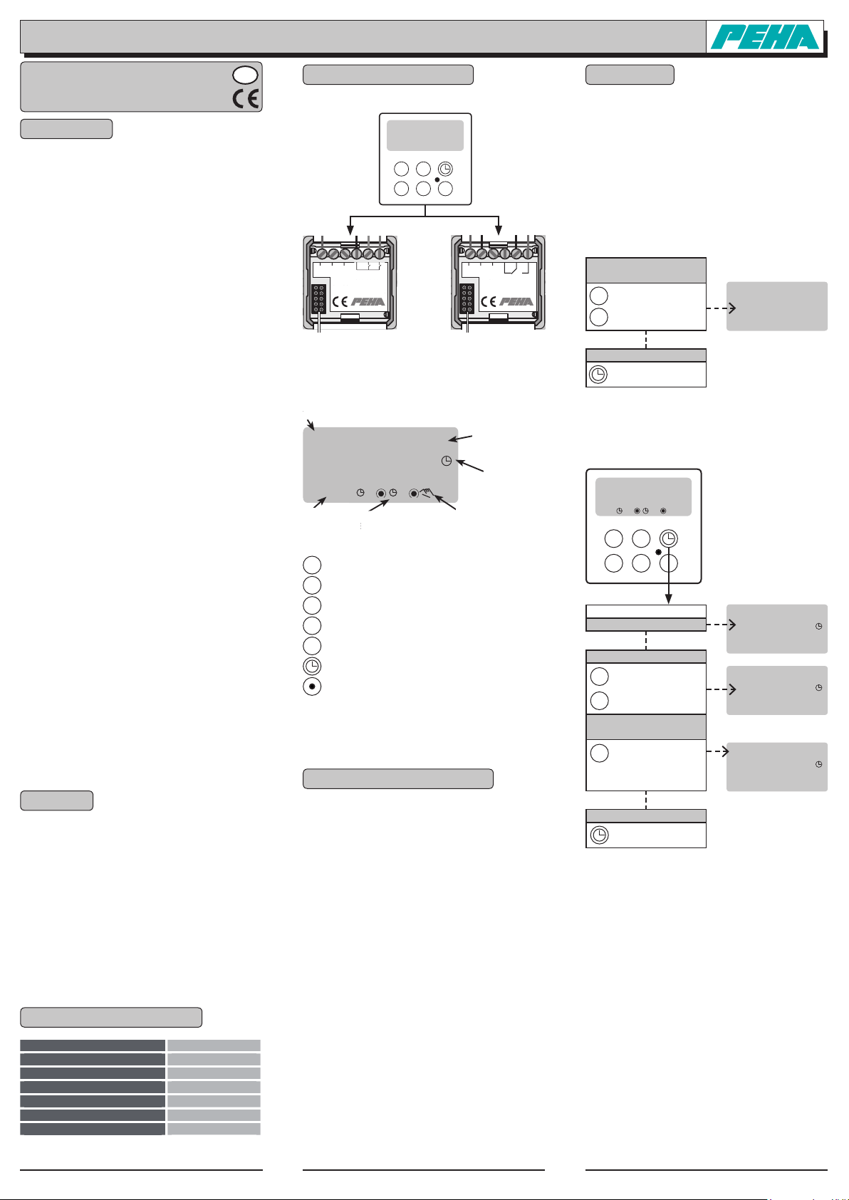
4. Structure et description
4.1 Vue d’ensemble et accessoires
4.2 Écran d’affichage et touches de commande
5. Installation et mise en service
5.1 Consignes d’installation importantes !!
– Ne retirer ou n’enficher la minuterie de ou dans la
douille enfichable qu’en cas d’alimentation électrique
déconnectée !
– À utiliser uniquement dans des locaux fermés.
5.2 Pose
• Procéderaumontageetàl’installationdel’insertàrelais
conformémentàlanotice(àconfieruniquementàunélec-
tricien spécialisé).
• Enficheravecprécautionlaminuteriedansladouilleen-
fichable.
5.3 Mise en service
• Mettre l’installation électrique sous tension
après la pose.
• Procéder au réglage de base (voir le point 6.1).
• Programmer les durées d’activation (voir le point 6.2).
6. Fonctions
6.1 Réglages de base
Il est nécessaire de procéder au réglage de base à la
première mise en service ou après une remise à zéro
(RESET).
1ère étape: Réglage du nombre des sorties
La minuterie est utilisée en combinaison avec l’insert à
relais 293/6 (une sortie) ou 293/2 (deux sorties). C’est
pourquoi, il est nécessaire de régler le nombre des sor-
ties à utiliser.
Le réglage est conservé également en cas de panne de
secteur et ne doit être effectué qu’une seule fois.
Remarque: Le réglage est activé automatiquement à la
première mise en service.
2e étape: Réglage de l’heure et du jour de la semaine
Remarques :
– Si aucune heure n’est mémorisée, le réglage de
l’heure et du jour de la semaine est activé automa-
tiquement.
– Si l’utilisateur appuie sur aucune touche, l’appareil
revient automatiquement en mode d’affichage de
base après 30 secondes.
293/2
230V~/µ4A 50Hz
L
1
08:15
�
�
day
prg ch
293/6
230V~/µ10A 50Hz
Minuterie
(291 Z)
Insert à relais
293/2
Douille enfichable pour
la partie supérieurel
Douille enfichable pour
la partie supérieurel
Insert à relais
293/2
Activation/Désactivation de la sortie 1
Activation/Désactivation de la sortie 2
Sélection du bloc semaine/jour de la semaine
Activation du mode de programmation
Réglage de la sortie/ des sorties
Réglage de l’heure et du jour de la semaine
Touche de remise à zéro (RESET)
Remarque : Les touches day et prg ne sont utilisées que
pour la première mise en service ou la programmation
de la minuterie.
p
p
day
prg
ch
-ENà
0ROGRAMMIERUNG
!NGABE DES !USGANGSKANALS
-ANUELLE"EDIENUN
G
-ENà
:EITEINSTELLUNG
Anzeige Ausgang 1 u. 2
(EIN/AUS, automatisch)
.POUBH
4QFJDIFSQMBU[
Commande manuelle
1 = Lundi
Affichage sortie 1 et 2
(ACTIVÉE/DÉSACTIVÉE,
automatique)
Menu de
programmation
Emplacement
de la mémoire
Menu de
réglage
du temps
Référence 291 Z
Hauteur de pose 0,8 à 1,5 m
Durée de parcours minimale 1 minute
Température ambiante de 0 °C à +40 °C
Température de stockage de – 25 °C à 75°C
Marquage CE
Type de protection IP20
Mettre n au réglage
à actionner
à actionner
brièvement
CH:02 = 2 sorties
CH:01 = 1 sortie
p
p
Réglage du nombre
des sorties
CH:01
L’heure clignote
à actionner pendant env. 3 s
1
00:00
1
15:45
1 2 3 4 5 6 7
15:45
Réglage de l’heure
à actionner brièvement:
Réglage des minutes
à actionner longuement:
Réglage des heures
p
p
Réglage du jour
de la semaine
à actionner
1 = Lu, 2 = Mar, 3 = Mer,
4 = Jeu,5 = Vend ...........
day
Mettre n au réglage
à actionner
00:00
C1 C2
1

291 Z (Rev01_080728) F - 2
Paul Hochköpper GmbH & Co. KG
Postfach 1727 • D-58467 Lüdenscheid • Tel.: +49 (0)2351 185-0 • Fax: +49 (0)2351 27666 • e-mail: [email protected] • Internet: www.peha.de
31060000-143
6.2 Programmation des heures d’activation
L’appareil peut activer/désactiver des consommables
via les heures d’activation. Il est possible de program-
mer 24 heures d’activation (01 à 24). Il est également
possible de sélectionner le jour de la semaine ou le bloc
de la semaine et l’état de commutation des sorties.
a) Ajout d’une heure d’activation
Remarques :
– Il est possible de mettre fin à tout moment au réglage.
– Le nombre des heures d’activation encore libres par ex.
avec rE:21 = 21 heures d’activation restantes s’affiche.
– Si l’utilisateur appuie sur aucune touche, l’appareil
revient automatiquement en mode d’affichage de
base après 30 secondes.
b) Modification de l’heure d’activation
Remarques :
– Il est possible de mettre fin à tout moment au réglage.
– Le nombre des heures d’activation encore libres par ex.
avec rE:21 = 21 heures d’activation restantes s’affiche.
– Si l’utilisateur appuie sur aucune touche, l’appareil re-
vient automatiquement en mode d’affichage de base
après 30 secondes.
c) Effacement de l’heure d’activation
6.3 Touche RESET
Appuyer brièvement sur la touche RESET pour remédier à
un dysfonctionnement. La programmation est conservée.
6.4 Sélection des réglages usine
Tous les réglages programmés par l’utilisateur et toutes
les heures d’activation sont effacés. Attention ! Il faut
ensuite procéder à un nouveau réglage de base !
Le réglage du nombre des sorties est ensuite activé
(voir la 1ère étape au point 6.1).
7. Commande
La commande de l’insert à relais a lieu automatiquement
via les heures d’activation programmées ou manuelle-
ment via les touches pet q. Il est, en outre, possible de
commuter l’insert à relais via deux postes secondaires.
7.1 Commande manuelle
Une commande manuelle est tout le temps possible. Le
symbole représentant une main « commande manuelle »
et la sortie correspondante (C1, C2) clignotent alors.
7.2 Fonctionnement automatique ACTIVÉ/DÉSACTIVÉ
Il est possible d’activer et/ou de désactiver le mode de
fonctionnement automatique avec les heures d’activation
programmées.
Affichages du mode de fonctionnement
automatique/manuel :
7.3 Fonction des postes secondaires (insert à relais)
Des boutons-poussoirs externes aux entrées des pos-
tes secondaires E1 et E2 de l’insert à relais ont la fonc-
tion suivante :
8. Recherche de pannes / dépannage
Installation nouvelle ou existante:
• Contrôler le coupe-circuit automatique et l’alimentation
électrique (électriciens professionnels).
• Contrôlerleconsommableconnectéetlescâblesdecon-
nexion (électriciens professionnels).
Insert à relais Fonction
Appuyer brièvement sur
le bouton-poussoir (E1)
Sortie 1
ACTIVÉE/DÉSACTIVÉE
Appuyer longuement (3s)
sur le bouton-poussoir (E1)
Sortie 1 ACT. / DÉS.
(sans automatique)
Appuyer brièvement sur
le bouton-poussoir (E2)
Sortie 2
ACTIVÉE/DÉSACTIVÉE
Appuyer longuement (3s)
sur le bouton-poussoir (E2)
Sortie 2 ACT. / DÉS.
(sans automatique)
Betriebsmodus Symboles
automatique
ACTIVÉ C1/C2 aDÉSACTIVÉE
C1/C2 aACTIVÉE
automatique
ACTIVÉ
+ manuel
C1/C2 apermanence DÉS.
C1/C2 apermanence ACT.
automatique
DÉSACTIVÉ
+ manuel
C1/C2
+ clignotement aDÉS.
C1/C2
+
clignotement aACT.
Jour de la semaine
Lun = 1, Mar = 2, Mer = 3, Jeu = 4, Vend = 5, Sam = 6, Dim = 7
Bloc de la semaine
Lun à dim (semaine entière)
a1 2 3 4 5 6 7
Lun à sam (longue semaine de travaul ) a1 2 3 4 5 6
Lun à ven (semaine de travail courte) a1 2 3 4 5
Ven à dim (long week-end) a5 6 7
Sam à dim (week-end court) a6 7
État de commutation des sorties C1 et C2
On obtient les états de commutation suivants dans cet
ordre si l’on utilise l’insert à relais 293/2 (deux sorties):
C1 O = DÉS. C2 O = DÉS.
C1 O = ACT. C2 O = DÉS.
C1 O = DÉS. C2 O = ACT.
C1 O = ACT. C2 O = ACT.
C1 O = DÉS. —
C1 O = ACT. —
— C2 O = DÉS.
— C2 O = ACT.
État de commutation de la sortie C1
On obtient les états de commutation suivants dans cet
ordre si l’on utilise l’insert à relais 293/6 (une sortie) :
C1 O = DÉS.
C1 O = ACT.
Mettre n au réglage
à actionner
16:05
prg
C1 C2
1
Réglage du bloc ou du
jour de la semaine
à actionner
brièvement
day
Réglage de l’heure
d’activation
à actionner brièvement:
Réglage des minutes
à actionner longuement:
Réglage des heures
p
p
à actionner
ch
Activation des sorties
07:45 Prog.
1 2 3 4 5
01 C1 C2
07:45 Prog.
1 2 3 4 5
01 C1 C2
--:--
Prog.
1 2 3 4 5
01 C1 C2
à actionner briève-
ment (01 à 24)
Ajout d’une heure
d’activation
prg
--:--
Prog.
1 2 3 4 5 6 7
02 C1 C2
Mode de programmation
(l’affichage clignote)
à actionner pendant env. 3 s
--:--
Prog.
1 2 3 4 5 6 7
01 C1 C2
Mettre n au réglage
à actionner
16:10
prg
C1 C2
1
Réglage du bloc ou du
jour de la semaine
à actionner
brièvement
day
Réglage de l’heure
d’activation
à actionner
ch
Activation des sorties
à actionner brièvement
Réglage des minutes
à actionner longuement
Réglage des heures
p
p
21:30 Prog.
1 2 3 4 5
02 C1 C2
21:30 Prog.
1 2 3 4 5
02 C1 C2
22:00 Prog.
1 2 3 4 5
02 C1 C2
à actionner briève-
ment (01 ...24)
Sélection de l’heure
d’activation
prg 22:00 Prog.
1 2 3 4 5 6 7
02 C1 C2
Mode de programmation
(l’affichage clignote)
à actionner pendant env. 3 s 07:45 Prog.
1 2 3 4 5
01 C1 C2
Mettre n au réglage
à actionner
Mode de programmation
(l’affichage clignote)
à actionner pendant env. 3 s
16:20
prg
C1 C2
1
à actionner briève-
ment (01 à 24)
Sélection de l’heure
d’activation
prg 22:00 Prog.
1 2 3 4 5 6 7
03 C1 C2
07:45 Prog.
1 2 3 4 5
01 C1 C2
Effacement de l’heure
d’activation
à actionner en
même temps
p
p
--:--
Prog.
1 2 3 4 5 6 7
03 C1 C2
à actionner
brièvement
à maintenir
enfoncée
prg
Réglages usine
CH:01
Minuterie Fonction
Appuyer brièvement
sur la touche p
Sortie 1
ACTIVÉE/DÉSACTIVÉE
Appuyer brièvement
sur la touche q
Sortie 2
ACTIVÉE/DÉSACTIVÉE
Minuterie Fonction
Appuyer longuement
(env. 3 s)
sur la touche p,q
AUTOMATIQUE DÉSACTIVÉE
Sortie en permanence
ACTIVÉE/DÉSACTIVÉE
Appuyer brièvement
sur la touche p,q
AUTOMATIQUE ACTIVÉE
Sortie ACTIVÉE/DÉSACTIVÉE
This manual suits for next models
2
Table of contents
Languages:
Other PEHA Timer manuals