Pehamed CD-LUX User manual

p e h a m e d
Instruction Manual
CD lux
Digital Luminance/
Illuminance Meter

2
Instruction Manual for the
technical device:
CD-LUX
Luminance/Illuminance Meter
Edition Date: May 2016
How to reach us:
pehamed
pehamed
pehamed
pehamed
PEHA Me . Geräte GmbH
Mühlstrasse 38
D-65843 Sulzbach/Ts.
Germany
Tel.: +49 6196 500 40 30
Fax:: +49 6196 500 40 50
E-mail: info@pehame . e

3
Table of Contents
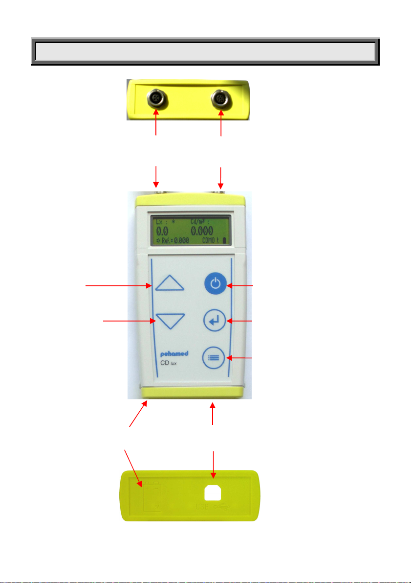
Device Description....................................................................
General Information ................................................................8
Start-Up .......................................................................................9
Measuring with the Luminance Detektor...............................11
Zeroing ........................................................................................12
Measuring in "Continuous Mode"............................................13
Measuring in "Trigger Mode" ....................................................14
Measurement of Image Display Devices...............................1
Measuring Veiling Luminance .................................................16
Measurement of Maximum Contrast .....................................17
Luminance Variations within One Image ..............................19
Measuring Luminance Variations............................................20
Measuring Uniformity of Viewing Box Luminance.................22
Measuring Viewing Box Luminance........................................24
Retrieving Stored Measurement Values.................................26
Examples.....................................................................................27
Measuring Ambient light in Lux ...............................................29
Menu ...........................................................................................30
LCD Display ................................................................................33
Switching-off .............................................................................34
Battery Change.........................................................................3
USB-Interface..............................................................................36
Sensors.........................................................................................37
Luminance Detector.................................................................38
Illuminance Detector................................................................40
Technical Specifications...........................................................41
Important Safety and Handling Informations for Batterys ...42

4
Dear Customer,
Congratulations on your decision to buy a high quality device
made by pehamed in state-of-the-art production facilities. This
product’s design and features fully comply with the relevant
national and international standards.
Our ISO 9001 certified Quality Management System ensures
that our products, assuming they are properly used, will have
an optimum useful service life.
As with all high value products, it is essential, for trouble-free
operation, that the operating instructions contained in this
manual are carefully followed.
IMPORTANT:
The basic CD-LUX unit and its sensors have been precisely
adjusted to each other under reference conditions in a
factory calibration process performed by pehamed.

5
Device Description
LUX SENSOR
INTERFACE SOCKET
cd/m² SENSOR
INTERFACE SOCKET
ON/OFF/ZERO
ENTER/OK/MEMORY/RESET
BATTERY BOX
MENU/SAVE/RESULT
UP
DOWN
USB INTERFACE

6
ON/OFF/ZERO button
To start or zero the unit, press this button down
for ca. 2 seconds until an acoustical signal
sounds. To switch off the unit , press and hold
down this button for ca. seconds.
ENTER/OK/MEMORY/RESET button
•Press this button to confirm a selected
menu item.
•Briefly press this button to save a
luminance measurement value.
•Press this button for ca. seconds to
delete the measurement values in the
memory.
MENU/SAVE/RESULT button
•Press and hold down this button for ca. 2
sec. to open the Set-up menu.
•Briefly press this button to save selected
menu items.
•Press this button for sec. until
“Calculate” appears in the LCD to
retrieve stored values.
„UP“ arrow button
To select a menu item, briefly press this button.
„DOWN“ arrow button
To select a menu item, briefly press this button.
USB-INTERFACE
interface for cable connection to a PC
SENSOR CONNECTION SOCKET (2x)
To connect the sensors delivered w/ the
unit.

7
Laser Classification
The laser used in the CD-LUX unit to align it with the
measurement point is classified according to VDE 0837 and
IEC 82 in Laser Class 2.
The permissible laser performance
of a continuous laser beam of this
class is limited to a maximum of
1 milliwatt (1 mw).
Adequate eye protection is
ensured by the lid closing reflex.
As a result, eye injury is only possible
if a person deliberately looks into
the laser beam for several seconds
while suppressing the lid closing
reflex.
DO NOT LOOK DIRECTLY INTO THE LASER !

8
General Information
The CD-LUX Luminance/Illuminance Meter has been designed
for use in conducting the acceptance and constancy tests
according to DIN 6868/1 7 "Acceptance and constancy
testing for image display devices,” the constancy tests as well
as the corresponding testing of viewing boxes per DIN
68 6/1+2.
The CD-LUX fulfills the requirements for luminance meters
according to DIN 032/7 Class B.
Luminance meters which are placed in direct contact with the
monitor surface are not suitable for the evaluation of existing
viewing conditions as they do not measure the contrast
reducing, reflected ambient light.
Thanks to its spacer leg, the CD-LUX is able to include
reflected ambient light in its measurements.
The built-in laser positioning aid of the CD-LUX enables its
precise alignment over the desired measurement point on the
monitor surface as the laser beam is so aligned that it
intersects the optical axis of the optical measurement system
at the monitor surface. In addition, the laser, together with the
laser control window, helps to ensure a perpendicular
alignment of the optical measurement system vis-à-vis the
monitor surface.

9
Start-up
The CD-LUX Luminance/Illuminance meter is delivered with a
pre-installed battery.
The unit is delivered with the following components:
•Basic unit
•9 Volt alkaline block battery (pre-installed in the unit)
•Sensors with cable
•Transport case
1. Snap the sensors into the sensor interface sockets
and loosely tighten the knurled fitting.
IMPORTANT! The CD-LUX must be switched off at this
time, otherwise the sensor will not be detected by
the unit’s software.
2. Now switch on the unit by pressing
the ON/OFF/ZERO button.
Then a self-test will run for a few seconds during
which the sensor will be detected.
Example:
Then a hard- and software self-test will run.
Pehamed CD
-
LUX
Version 2.02

10
The following display information depends upon the sensor type
connected.
Example:
Following completion of the above display sequence, the CD-LUX is
ready for use.
The display now shows 0.000 for all measurement values.
Lx: Cd/m²:
0,00 0,000
⇒ Ref=0.000 CDMO
CDMO
-
Sensor erkann
CDMO 1,054 as

11
Measuring with the Luminance Detector
The hand-held luminance detector has a measurement range
of ca. 0.0 cd/m² to 80,000 cd/m² and automatically switches
the measurement range to kcd/m² as needed.
Up to a measured luminance value of 10,000 cd/m², the direct
value is shown (e.g. 4, 00.68 cd/m²).
For values ≥ 10,000 cd/m² a small k (kilo) appears in front of the
cd/m².
e.g. 6,690 kcd/m² (= 6,690 cd/m²).

12
Zeroing
The CD-LUX can be manually reset to zero. The unit is zeroed
during factory calibration and does not normally become
misadjusted.
IMPORTANT! Nevertheless, we recommend that you zero the
unit prior to each measurement series and/or in case you
should see improbable measurement values.
Please proceed as follows:
•Switch on the unit by pressing the
ON/OFF/ZERO button.
•After the self-test press the MENU
button until an acoustical signal is
heard.
•Set the “Zero-enable-on” menu item by pressing the
ENTER button and exit the menu by pressing the MENU
button again.
•Close the black cylindrical housing of the optical
measurement system of the hand-held detector with
the enclosed cap!
•Perform a measurement by pressing and releasing the
ON/START button on the hand-held detector.
•Press the ON/OFF/ZERO button
until an acoustical signal is heard.
•The display will now show:
The zero adjustment process is finished, and the normal
measurement value display will reappear.
Zero
⇒
⇒⇒
⇒
⇒
⇒⇒
⇒
Off
Zero

13
Measuring in “Continuous Mo e”
The CD-LUX can be switched by menu item selection into two
different measurement modes (See the Chapter “Menu“). In
“Continuous Mode,” the unit is switched in such a way that the
hand-held luminance detector continuously transmits new
signals every ca. 2 seconds which then appear in the display
as measurement values.
•When the CD-LUX is switche on in “Continuous Mo e,”
measurements automatically begin.
•Align the blinking red laser point of the hand-held
detector over the desired measurement point on the
monitor or viewing box while keeping the spacer leg of
the detector in direct contact with the display device
surface (as closely as possible in a perpendicular, (90°),
angle).
•Hold the detector steady during the measurement
cycle. A blinking asterisk (*) will appear above the
respective measurement value during the
measurement cycle which takes ca. 2 seconds.
•After a software click the new measurement value is
briefly displayed, and the next measurement starts
automatically.

14
Measuring in “Trigger Mo e”
In “Trigger Mode,” the unit is switched in such a way that the
sensor only transmits a signal after the blinking red laser point
has been switched on by pressing the ON/START button on the
hand-held luminance detector, and the measurement has
been started by releasing this button.
•Press and hold down the ON/START button on the rear
side of the hand-held luminance detector to switch on
the blinking red laser.
•Align the blinking red laser point of the hand-held
detector over the desired measurement point on the
monitor or viewing box while keeping the spacer leg of
the detector in direct contact with the display device
surface (as closely as possible in a perpendicular, (90°),
angle).
•Release the ON/START button to start the measurement.
•Hold the detector steady during the measurement
cycle. A blinking asterisk (*) will appear above the
respective measurement value during the
measurement cycle.
•The measurement cycle takes ca. 2 seconds, and the
measurement values remain on display until the next
measurement is started as described above or the unit
is switched off.

15
Measurement of Image Display Devices
•The Veiling Luminance is measured with the image
display device switched off, under normal viewing
conditions at the work place. The ratio between the
Maximum White Luminance (determined during the
measurement of the Maximum Contrast) of the image
display device and the measured Veiling Luminance
must be > 100 for Class 1 devices, > than 40 for Class 2
devices.
The following table contains typical maximum white
luminance values and the corresponding maximum
permissible veiling luminance values.
Max. White
Luminance (cd/m
2
) Veiling Luminance of
Switched off Display
Device (cd/m
2
)
100 < 1.0
300 < 3.0
Performance
Class 1
500 < 5.0
100 < 2.5
200 < 5.0
Performance
Class 2
300 < 7.5

16
Measuring Veiling Luminance
•Switch on the CD-LUX by pressing the ON/OFF/ZERO
button. 0. 0 0 0 appears in the display.
•Press and hold down the ON/START button on the hand-
held detector which activates the laser. Continue to
hold down the button, and align the blinking red laser
point over the measurement point for veiling luminance
in the center of the switched off monitor while bringing
the spacer leg into direct contact with the monitor
surface in a perpendicular angle. Release the
ON/START button to start the measurement.
•Hold the detector steady during the measurement
cycle. A blinking asterisk (*) will appear above the
respective measurement value during the
measurement cycle.
•The measurement cycle takes ca. 2 seconds, and the
veiling luminance measurement value in cd/m² remains
on display until the next measurement is started as
described above or the unit is switched off (only in
“Trigger Mode”).

17
Measurement of Maximum Contrast
The Maximum Contrast is measured with the image display
device switched on with the corresponding test pattern. Two
values, the Minimum Luminance (Gray Value) L
min
and the
Maximum Luminance (White Luminance) L
max
must be
measured. The following values apply for the ratio L
max/
L
min
for
monitors of the various performance classes:
Performance Class 1: L
max
/L
min
> 100
Performance Class 2: L
max
/L
min
> 40
These are the same limiting values which apply to the Veiling
Luminance.
Note: The Minimum Luminance (Gray Value) is ≥ Veiling
Luminance as the Minimum Luminance is made
up of the Veiling Luminance and the Minimum
Luminance of the image display device.
Measuring Maximum Contrast
•Switch on the CD-LUX by pressing the ON//OFF/ZERO
button. 0. 0 0 0 appears in the display
•Press and hold down the ON/START button on the hand-
held detector which activates the laser. Continue to
hold down the button, and align the blinking red laser
point over the measurement point for Minimum
Luminance on the test pattern while bringing the
spacer leg into direct contact with the monitor surface
in a perpendicular angle.
•Release the ON/START button to start the measurement.

18
•Hold the detector steady during the measurement
cycle. A blinking asterisk (*) will appear above the
respective measurement value during the
measurement cycle.
•The measurement cycle takes ca. 2 seconds, and the
measurement value for the Minimum Luminance L
min
in
cd/m² remains on display until the next measurement is
started as described above or the unit is switched off
(only in “Trigger Mode”).
•Note the measurement value for L
min.
•Repeat the above measurement procedure for the
Maximum Luminance L
max
and note its measurement
value.
•Calculate the ratio L
max
/L
min.

19
Luminance Variations within one Image
Use either the test pattern for geometrical image
characteristics or the SMPTE test pattern (See DIN 6868/ 7) to
measure luminance variations within a isplaye image.
First make one measurement near the center of the image M1
and then one measurement each in each of the 4 corners of
the image.
The measurement points must be located within an area of
uniform density with a gray value corresponding to 0% of the
maximum signal level. The measurement points must not be
overlapped by other information or structures (step wedge,
bar pattern, grid etc.).
The following table lists the limits for permissible variations in
luminance of the corner measurement points vs. the
luminance of the central measurement point M1 by
performance class of the image display device:
Permissible Luminance Variations for Image
Display Devices with
Cathode Ray Tube Flat Screen
Performance Class 1
-30% of M1 ±1 % of M1
Performance Class 2
-3 % of M1 ±20% of M1

20
Measuring Luminance Variations
•The desired test pattern must be displayed on the
monitor. Measure the middle point M1 at 0% of the
maximum signal level and the 4 corner points E1, E2, E3
and E4.
•Switch on the CD-LUX by pressing the ON/OFF/ZERO
button. 0. 0 0 0 appears in the display.
•Press and hold down the ON/START button on the hand-
held detector which activates the laser. Continue to
hold down the button, and align the blinking red laser
point over the central measurement point M1 on the
test pattern while bringing the spacer leg into direct
contact with the monitor surface in a perpendicular
angle.
•Release the ON/START button to start the measurement.
•Hold the detector steady during the measurement
cycle. A blinking asterisk (*) will appear above the
respective measurement value during the
measurement cycle.
•The measurement cycle takes ca. 2 seconds, and the
luminance measurement value for M1 in cd/m² remains
on display until the next measurement is started as
described above or the unit is switched off (only in
“Trigger Mode”).
•To store this value, briefly press the ENTER button. An
acoustical signal is emitted at the beginning and the
end of the storage cycle, and the word “Memory”
briefly appears in the display.
Table of contents
Other Pehamed Measuring Instrument manuals
Popular Measuring Instrument manuals by other brands

Compressed Air Alliance
Compressed Air Alliance POM200x00 user manual

Electro-Sensors
Electro-Sensors TR400 Installation & operation manual

Agatec
Agatec A510S user manual

Smart Balancing
Smart Balancing PFM Flex 1 Operation manual

Extech Instruments
Extech Instruments CO15 user manual

Amptek
Amptek X-123SDD quick start guide