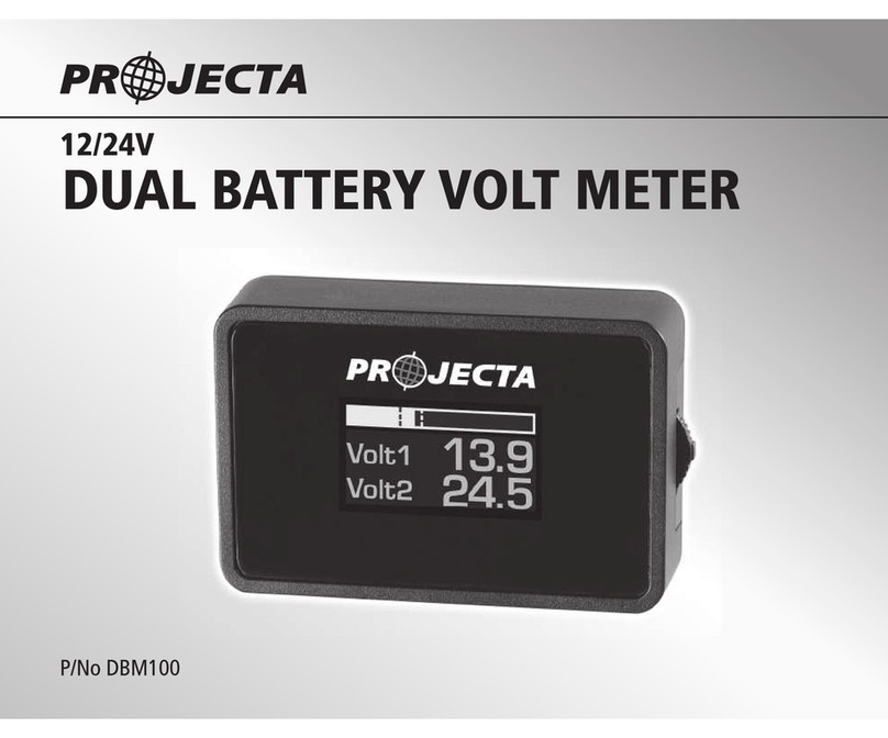
Projecta DBM100 User manual

12 VOLT
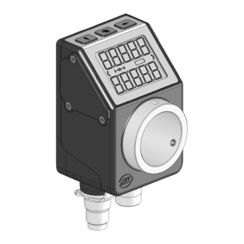
DUAL BATTERY VOLT METER
P/No DBM100

WARNING
• Before installation, please make sure that the vehicle is stationary, the engine is switched off and cool.
• This product is designed for use in vehicles with a 12V electrical system O LY.
• Be careful when laying wires, not to cause any electrical shorts or wire breakage.
• The audio and clock memory data may be lost if the negative (-) battery cable is disconnected. Please
re-set the necessary data after installation.
• In case anything abnormal occurs after installation, please double check and ensure that black wire
is securely connected with ground terminal.
FEATURES
L.E.D DUAL VOLTAGE DISPLAY
Sharp and crisp coloured LED display allows you to monitor the condition of your batteries.
HIGH/LOW VOLTAGE WA NING
The DBM100 alerts you to high or low battery voltage allowing you to maintain your batteries in
peak condition and get the most from your dual battery system.
ADJUSTABLE DAYTIME/NIGHT-TIME B IGHTNESS
Adjust between 10 levels of daytime/night-time brightness.
AUTOMATIC DIMME
Wire to the vehicles head lamp circuit for automatic dimming when head lamps are switched on for
more comfortable night viewing.

Meter cable
5 pin
Green To fuse and headlamp circuit (+12 volts)
to activate automatic dimmer.
Yellow To fuse and “+” positive terminal
of battery 1.
Red To fuse and +12V ignition
switch circuit.
Black To a good earth.
Blue To fuse and “+” positive terminal
of battery 2.
13.2
10.6
Volt 1
Volt 2
BATTERY 1
(STARTER BATTERY)
DBM100
IGNITION
SWITCH
HEADLIGHT
CIRCUIT
FUSE BOX
BATTERY 2
(AUX BATTERY)
YELLOW
RED
GREEN
BLUE
BLACK
BLACK BLACK
OFF
ACC
ON
1A FUSE
Note: Fuses not included with unit, it is recommended fuses are installed where shown on the above wiring diagram.
1A FUSE
1A FUSE
WI ING DIAG AMS
INSTALLATION
1. Disconnect the negative (-) battery cables
from battery 1 & battery 2.
2. Connect the 5 wires as per the WIRI G
DIAGRAMS. (When crimping, fold wire over
numerous times to increase thickness of wire
to aid connection).
ote: If shortening of the cable or insulation
is required, remove excess shielding wire.
3. Reconnect the negative (-) battery cables
to battery 1 & battery 2.
4. Turn on the engine and check that the
DBM100 is working.
5. Clean the surface of the location where
you intend to attach the meter.
6. Use the provided double-sided tape to
stick the meter to the surface.

OPERATIONS & SETTINGS
GETTING STA TED
The DBM100 allows you to customise the display and settings to best suit your batteries and application.
Step 1 To begin the set up mode press “E TER” and hold down for 2 seconds.
Step 2 Adjust the settings by scrolling “UP/DOW ” until the desired value is reached.
Step 3 Press “E TER” to confirm the settings and move into next stage.
The following diagrams illustrate each of the 6 stages that can be customised in the order they appear.
ote: “Battery 1” displayed as “Volt 1”, “Battery 2” displayed as “Volt 2”.
Switch ENTER : Press and hold for 2 seconds to start set-up mode
UP : Scroll Up to show PEAK information consecutively
DOWN : Scroll Down to change display mode (4 screens)
13.2
10.6
Volt 1
Volt 2
Enable
Volt 2 Day-Bright
7
Volt 1 High
15.0V
Volt 1 Low
10.0V
Volt 2 High
15.0V
Volt 2 Low
10.0V
2
Night-Bright
(1) Sethigh
warninglevel
of Battery 1
(2) Setlow
warninglevel
of Battery 1
(3) Battery2:
Enable/Disable
Battery2
(4) Set high warning
data of Battery 2
(if Battery 2 is enabled.)
(5) Set low warning
data of Battery 2
(if Battery 2 is enabled.)
(6) Set adjustable day
& night brightness
levels.
Night bright level can
only be set when dimmer
mode is activated ie:
headlightson.

DISPLAY MODE
The DBM100 features 4 display options to best suit your application.
Display 1 Display 3
Battery 1 only Battery 1 & 2 (level indicator shows battery 1)
Display 2 Display 4
Battery 2 only Battery 2 & 1 (level indicator shows battery 2)
To change between the display options, scroll “DOW ” repeatedly until desired display is showing.
PEAK ECALL MODE
Peak recall records and allows you to review the peak voltage of your batteries at any given time.
Step 1 Scroll “UP” to show peak data of battery 1 and 2 consecutively.
Step 2 Scroll “DOW ” to reset the data.
Step 3 Press “E TER” to exit peak recall mode and return to normal display.
HIGH/LOW VOLTAGE WA NING
The DBM100 will alert you if either of your batteries reach the high or low voltage level (see “Getting
Started” stages 1–2 & 4–5), allowing you to correct the problem and prevent permanent battery damage.
When a high or low voltage is reached, the screen will flash and the voltage in question will be highlighted.
High Voltage warning:
High voltage warning may indicate a problem with the vehicle’s alternator or circuitry.
Low Voltage warning:
Recharge the battery immediately. Failure to do so may cause permanent battery damage.
V
Volt 2
10.6
V
Volt 1
13.2
Volt 1
Volt 2
13.2
10.6
Volt 2
Volt 1
10.6
13.2
High
1
Volt 1 V
14.5
Peak
Volt 2 V
12.9
Peak
High
1
Volt 1
Volt 2
13.2
15.4

CALIB ATION MODE
(For Advanced Users Only)
Note: The DBM100 is ready for use and has been calibrated using certified equipment.
Advanced users wishing to calibrate the voltage settings to meet specific requirements can do
so by following the steps below.
Step 1 Turn off engine.
Step 2 Hold down “E TER” and turn engine on, hold down until unit screen lights up.
Step 3 Press “E TER” once screen lights up showing “Calibration for advanced user only”.
Step 4 Scroll “UP/DOW ” to select calibration data for battery 1.
Step 5 Press “E TER” to set calibration data for battery 1.
Step 6 Scroll “UP/DOW ” to select calibration data for battery 2.
Step 7 Press “E TER” to set calibration data for battery 2 and return to display mode screen.
Calibration
For Advanced
User Only!
VVolt 2
10.6
Calibration
VVolt 1
13.2
Calibration

CONTENTS
DBM 100
Dual voltage meter x1
Double-sided tape x2
Instruction manual x1
SPECIFICATIONS
P/No: DBM 100
Current Draw (Ignition O ): Battery 1 – 26.4mA
Battery 2 – 1.0mA
Ignition – 0.5mA
Current Draw (Ignition OFF): Battery 1 – 9.4mA
Battery 2 – 1.0mA
Ignition – 0mA
Operating Range: Battery 1: 5V–18V
Battery 2: 0–18V
Cable Length: 1.5m
Size (mm): 55 x 35 x 15
BATTE Y ANGE
Display ange
Battery 1 5–18V
Battery 2 0–18V

Distributed by
AUST ALIA
Brown & Watson International Pty Ltd
Knoxfield, Victoria 3180
Telephone (03) 9730 6000
Facsimile (03) 9730 6050
ational Toll Free 1800 113 443
NEW ZEALAND
Narva New Zealand Ltd
22–24 Olive Road
PO Box 12556 Penrose
Auckland, ew Zealand
Telephone (09) 525 4575
Facsimile (09) 579 1192 IS132
Issue 2: 20.01.12
Other manuals for DBM100
1
Other Projecta Measuring Instrument manuals