PEI 90PUNTPI11 User manual

90PUNTPI11 –90PUNTPI12 –90PUNTPI13 –90PUNTPI21 –90PUNTPI22 –90PUNTPI23
-13 -
EN
INDEX
1. GENERALINSTRUCTIONS
1.1 Manufacturerand welding machine identification data
1.2 General safetywarnings
1.3 Prevention measures tobe taken by the user
1.4 Technical data
1.5 Intended and non intended use
1.6 Description of the product and howit works
2. INSTALLATION INSTRUCTIONS
2.1 Environmental conditions
2.2 Energy requirement
2.3 Connection tothe energy sources
2.4 Transporting, storage and assemblyinformation
3. INSTRUCTIONSFOR THEOPERATOR
3.1 Description of the functions
3.2 Guide tostarting the welding machine forthe first time
3.3 Getting ready toweld
3.4 Influence of the different welding parameters
3.5 Checking spot quality
3.6 Operating guide
3.6.1Operating guide forautobody repairworks
3.7 Description of the welding control unit
3.8 Howtoeliminatewelding defects
4. MAINTENANCEINSTRUCTIONS
4.1 Maintenance information
4.2 Guide tomaintenance
1. GENERALINSTRUCTIONS
1.1MANUFACTURERAND WELDING MACHINEIDENTIFICATION DATA
Manufacturerdata
P.E.I.-POINTSRL
ViaMartinPiva, 34
35010 Limena / Padova / Italy
Tel. +39 049 8840695 / 8848052 Fax +39 049 8841129 e-mail: info@pei-point.com
Welding machinedata
Resistance type welding machine;see the dataplateon the machine and the certificateofconformityattached tothismanualfor
the model, serial numberand yearof construction.
Introduction
Thismanual contains the information needed toinstall, use and service yourwelding machine.
Followthe instructions toget the best out of yourwelding machine, inthe most economical way and incompletesafety.

90PUNTPI11 –90PUNTPI12 –90PUNTPI13 –90PUNTPI21 –90PUNTPI22 –90PUNTPI23
-14 -
1.2GENERALSAFETY WARNINGS
THEFAILURETOOBSERVE THESE WARNINGSAND/OR ANYMODIFICATION OFOR TAMPERING WITHTHEWELDING
MACHINEWILL RELEASE THEMANUFACTURERFROMANYLIABILITIES INTHECASE OFACCIDENTS TOPEOPLEOR
DAMAGETOTHINGSAND/OR TOTHEWELDING MACHINEITSELF. Beforeturning thewelding machineon itisessential
thattheuserknowshowtocarryoutall theoperationsdescribedinthismanual. Themanual isanintegral ofthemachine
and mustbekeptuntil itisdisposedof.
RESIDUALRISKS: Byresidualrisks wemean any hazardthatcouldnotbe totallyeliminated withthe design orprotection means
and any potential hazardthat isnot evident.
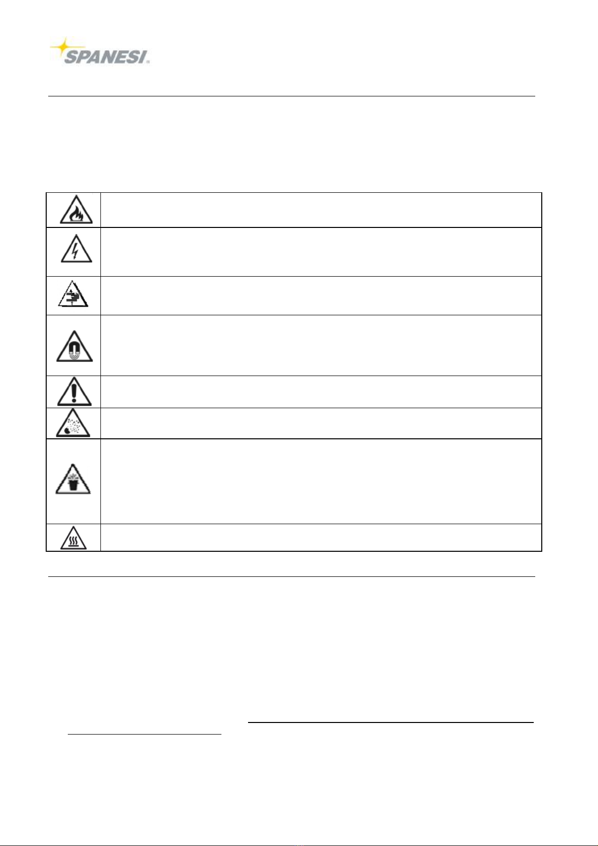
Theremust not be excessive quantities of dust, acids, corrosive substances orgases etc., on the premise
sexcept those
generated by the welding machine. Werecommend keeping anextinguisherneartheworkstation.
It must not be excessivelyhumidon the premises. Werecommend using aninsulating platform.
All maintenance jobs must be done on the machine onlyafterhaving disconnected it fromthe electricitymains.
Warning: high tension stored (600 VDC
). Beforedoing anything inside the welding machine wait at least 6minutes after
having cleared the voltage
Beverycarefulwhereyour
hands areputwhen operating the welder;always keep themaway fromthe area ofthe
electrodes and fromthe moving partsduring the welding cycleand maintenance.
The strong magneticfieldgenerated by the welding machine during welding can be verydangerous forthose with
pace-makers. Watches and electronicdevices ingeneral placed nearby can be damaged.
Somegood sense must be used toreduce the exposition of the human body tothe electromagneticfields:
keep the cables and the welding clamps as faraway as possiblefromthe body.
Donot stand between the twocables of the spotter; possiblykeep bothcables on the sameside of the body.
Onlyuse the spot welderon ahorizontal plane. If it slantsmorethan 15°withrespect tothe floorit couldtipover.
Anincorrect adjustment of welding pressure, an erroneous setting of parametersormalfunctioning of the pneumatic
systemcan all cause squirtsof melted material during welding.
The spot-weldermustonlybe used on ahorizontalplane.Aninclination ofmorethan 15°withrespecttothe floor
couldcause tipping over.Anerroneous adjustmentofthe welding pressure,awrong setting ofthe parametersorbad
functioning of the pneumaticsystemmay cause splashes of melted material during welding.
The welding clampand the spotterareconnected tothe samesource ofcurrent. When one ofthese devices isused,
the otherisalways underlive.The toolthatisnotused mustthereforebe putaway inthe appropriateinsulated
bracket. Otherwise,theremay be splashes ofwelding materialand sparks thatmay damage the equipmentorbe
dangerous forthe operators.
The electrodes becomeveryhot during welding. Donot touch themwithyourbarehands immediatelyafterwelding.
1.3PREVENTION MEASURES TOBETAKENBYTHEUSER
•Werecommend wearing safetyglasses.
•The usermust observe the safetyinstructions given on the welding machine.
•Personal protection gearmust complywithand be certified by current standards.
•Signs must be placed inthe vicinityof the machine relative tothe risks that call forpersonal protection gear.
•Itiscompulsorythattheuserobserve theaccidentprevention lawsinforce inhiscountry.
•Justoneoperatorwho has beenspecificallytrainedtouse welding machines and welding equipmentcanuse the
welding machine.
•Install asuction unitifthematerial tobeweldedproduces fumes.
•Theoperatormustwearglasses toprotecthiseyes againstsquirtsofmeltedmaterial, aprotective apron and leather
gloves.
•Theoperatormustavoidwearing metal objects(bracelets, watches etc.)
•Routineand extraordinarymaintenance jobsmustonlybedoneon themachineafterhaving disconnectedthepower
sources (electricity, pneumaticpower).
•Make surethemachineisearthedeffectivelyand protectedbyasuitableresidual currentcircuitbreaker(RCB)or
ground faultcircuitbreaker(GFCB).

90PUNTPI11 –90PUNTPI12 –90PUNTPI13 –90PUNTPI21 –90PUNTPI22 –90PUNTPI23
-15 -
1.4TECHNICALDATA
90PUNTPI11 90PUNTPI12 90PUNTPI13
Rated output @50% dutycycke kVA 10 25 13
Secondarymax welding current kA 11,5 11,5 15
Three-phase supplyvoltage +/-10% V 400 400 400
Mains frequency Hz 50/60 50/60 50/60
Delayed fuses A 32 32 32
Secondaryno load voltage V 16 16 6,2
PNEUMATICWELDING GUN 245
Welding capacityon steel mm 2,5+2,5 2,5+2,5 ---------
Electrodes force daN 245 245 ---------
Welding cablelength mm 2500 2500 ---------
Welding cablesection mm² 150 150 ---------
Armsdiameter mm 20 20 ---------
Electrodes diametermm 12 12 ---------
PNEUMATICWELDING GUN 370
Welding capacityon steel mm --------- 3+3 3+3
Electrodes force daN --------- 370 370
Welding cablelength mm --------- 2500 ---------
Welding cablesection mm² --------- 150 ---------
Armsdiameter mm --------- 24 24
Electrodes diametermm --------- 12 12
PNEUMATICWELDING GUN 560
Welding capacityon steel mm --------- 3+3 3+3
Electrodes force daN --------- 560 560
Welding cablelength mm --------- 2500 ---------
Welding cablesection mm² --------- 150 ---------
Armsdiameter mm --------- 24 24
Electrodes diametermm --------- 12 12
SPOTTERGUN (singlesided)
Gun cablelength mm 2500 2500 ---------
Ground cablelength mm 2500 2500 ---------
Gun and ground cablesection mm² 150 150 ---------

90PUNTPI11 –90PUNTPI12 –90PUNTPI13 –90PUNTPI21 –90PUNTPI22 –90PUNTPI23
-16 -
1.4TECHNICALDATA
90PUNTPI21 90PUNTPI22 90PUNTPI23
Rated output @50% dutycycke kVA 10 25 13
Secondarymax welding current kA 10 10 11
Three-phase supplyvoltage +/-10% V 200 200 200
Mains frequency Hz 50/60 50/60 50/60
Delayed fuses A 63 63 45
Secondaryno load voltage V 13,5 13,5 6,2
PNEUMATICWELDING GUN 245
Welding capacityon steel mm 2,5+2,5 2,5+2,5 ---------
Electrodes force daN 245 245 ---------
Welding cablelength mm 2000 2000 ---------
Welding cablesection mm² 200 200 ---------
Armsdiameter mm 20 20 ---------
Electrodes diametermm 12 12 ---------
PNEUMATICWELDING GUN 370
Welding capacityon steel mm --------- 3+3 3+3
Electrodes force daN --------- 370 370
Welding cablelength mm --------- 2000 ---------
Welding cablesection mm² --------- 200 ---------
Armsdiameter mm --------- 24 24
Electrodes diametermm --------- 12 12
PNEUMATICWELDING GUN 560
Welding capacityon steel mm --------- 3+3 3+3
Electrodes force daN --------- 560 560
Welding cablelength mm --------- 2000 ---------
Welding cablesection mm² --------- 200 ---------
Armsdiameter mm --------- 24 24
Electrodes diametermm --------- 12 12
SPOTTERGUN (singlesided)
Gun cablelength mm 2500 2500 ---------
Ground cablelength mm 2500 2500 ---------
Gun and ground cablesection mm² 150 150 ---------
1.5 INTENDEDAND NON INTENDEDUSE
Thefailuretoobserve theprescribedinstructionsconstitutes acondition ofimproperuse fromatechnicalpointofview
and as regardsthesafetyofpeople.
Intendeduse conditions
Weldersmust onlybe used forwelding metalskeeping withinthe powerlimitsgiven on the dataplate.
Onlyone trained operatorisallowed touse the machine withexperience tohandlewelding equipment.
Non intendeduse conditions
Welderscannot be used toexert pressureordeformmaterials.
It isforbidden toweldmaterialsthat can generatetoxicvapoursorcause explosions due toheating.

90PUNTPI11 –90PUNTPI12 –90PUNTPI13 –90PUNTPI21 –90PUNTPI22 –90PUNTPI23
-17 -
1.6 DESCRIPTION OFTHEPRODUCTAND HOW ITWORKS
Thiswelderbelong tothe familyof resistance type welding machines.
Bythiswemean autogenous welding obtained by pressure,withoutusing weldmaterial, using the thermaleffectofelectricity
flowing through the componentstobe welded (Jouleeffect)forheating.
The componentstobe welded aregripped between twoelectrodes withadualpurpose:toletelectricitypass through and toexert
enough force forwelding.
The intensityofthe current, the force on the electrodes and weldtimearethe mostimportantparametersforwelding.Force must
be applied during the electrodes’ squeeze timephases, weldtimeand holding time.
The welding controlunit manages the welding cyclephases;the times setaregiven in1/100 sec when themains frequency is50
Hzand 1/120 sec. when the mains frequency is60 Hz.
The mainswitch turns the welding machine on (item6)which also has the function of an emergency stop switch.
Welding isstarted eitherby the REDbutton on the gun (1)orthe leverswitch (trigger) on the studdergun (2).
The welding machine isequipped withsafetythermostatstostop operation if it overheats.
2. INSTALLATIONINSTRUCTIONS
2.1ENVIRONMENTALCONDITIONS
Operating clearances: The machine mustbe positioned toensureworking and maintenance clearances and forany emergency
situations that may arise. Forthisreason werecommend leaving aclearance of about 1metreall around the machine.
Environmentalcharacteristics: The place wherethe machine isgoing tobe used must be suitablyilluminated forbothproduction
and maintenance, free fromdust, acids, corrosive substances orgases, withtemperatures ranging between +5°C and +40°C.
Altitude must be less than 1000 metres. Relative airhumidity: 50% up to40°C / 90% up to20°C
Floor: The machine must be put on aflat surface that must also be abletowithstand itsweight.
2.2ENERGYREQUIREMENT
Electricity Pneumaticenergy
Model Mains power
(three-phase power) kVA
Airconsumption See technical data
400V 20 Minimumcircuit pressure 6,5bar=Kpa 650
200V 20
2.3CONNECTION TOTHEENERGYSOURCES
Qualified personnel who can also certifytheirworkmust install the machine.
THEINSTALLERISRESPONSIBLEFOR ACORRECTINSTALLATION AND,INPARTICULAR,FOR THECHOICEOF
DEVICES TOPROTECTAGAINST SHORTCIRCUITING,OVERLOADS,LEAKAGECURRENTS INTHECASE OFAFAILURE
AND OFTHEWIRES USEDTOCONNECTTOTHEMAINSWHICH MUST COMPLYWITHCURRENTLAWSAND
STANDARDS.THEINSTALLERMUST ALSOCHECKTHAT THEEARTHING SYSTEM,TOWHICH THEWELDING MACHINE
ISCONNECTED,ISEFFECTIVE. THEMACHINEMUST BECONNECTEDWITHAPLUG TOTHEPOWERSOURCEIN
ORDERTOBEUNDERTHEOPERATOR SURVEILLANCE.
Electrical connection
Modello Rated current of delayed action
fuses orcircuit breaker Supplycablecross section up to
20 metres
400V 32 16 mm2
200V 63 16 mm2
-Check machine platedatabeforeconnecting it (voltage rating, nominal frequency and numberof phases).
-Connectthewelding machinetoanRCD withaminimum currentdispersion of30 mA.
-The welding machine mustbe protected witheitherdelayed line fuses oracircuit breakerwiththe values given inthe above
table.
Pneumaticconnection
Connect the airpipe, withan inside diameterof minimum7mm, tothe inlet coupling.

90PUNTPI11 –90PUNTPI12 –90PUNTPI13 –90PUNTPI21 –90PUNTPI22 –90PUNTPI23
-18 -
2.4DATAON TRANSPORTING, STORAGEAND ASSEMBLY
Shipping: Make surethatthe means used totransportthe welding machine isstrong enough towithstand itsweight. Pay attention
tothe airconnections and projecting partstoavoidany damage being done.The weightsofthe differentmodelsaregiven inthe
technical data.
Unpacking –Assembly: Remove the packaging fromthe welding machine withcare,checking thatall the accessories areinside
and that nothing has been damaged during shipping.
THEPEOPLEINCHARGEOFLIFTING AND POSITIONING THEMACHINEMUST BE SUITABLYQUALIFIED.
3. INSTRUCTIONS FORTHE OPERATOR
3.1DESCRIPTION OFTHEFUNCTIONS
Toweld,the operatorcan eitherpress the red button on the gun oruse the leverswitch on the studdergun. Squeeze timetestscan
be run withoutwelding by pressing the black push button on the top ofthe handle.When the welding controlunit receives consent
tostartthe cycleit performsthe welding sequence according tothe parametersseton it. The sequence can be interrupted atany
timeby releasing the cyclestartpush button. Ifthestart pushbutton isreleasedduring weldtime,thespotmightnotbe
strong enough.
3.2GUIDETOSTARTING THEWELDING MACHINEFOR THEFIRST TIME
a) check thereiscompressed air
b) check that the level of the coolant liquidissufficient (see tab. below)
c) poweron viathe mainswitch
d) set the required electrode force by means of the pressureadjuster
e) set welding parameterson the control unit (see next paragraph)
Itispossibletouse only(clean)waterorwaterand glycol monopropylenewiththefollowing percentage:
Coolantliquid
Ambient temperature(°C) Glycolepercentage (%)
0-
-5 14
-10 23
-15 30
3.3GETTING READYTOWELD
WELDING CYCLE: The welding cycleconsistsof three basictimes:
Squeeze time: it isthe interval of timebetween the start of the cycleand the moment the electrodes, underthe force exerted
on them, comeintocontact withthe piece tobe welded.
Weldtime: thisisthe timeduring which the welding current passes through the electrode contact area.
Holding time: thisisthe timeduring which the force of the electrodes ismaintained afterweldtimehas finished.
The welding cyclecan be divided indifferenttimes;foramoredetailed explanation of thisplease read the paragraph relative tothe
welding control unit.
3.4INFLUENCEOFTHEVARIOUSPARAMETERSON THEWELDING RESULT
Force on theelectrodes: The greaterthe force ison the electrodes,the weakercontactresistance will be between the electrodes
and the sheetsand the less risk therewill be ofmeltedmaterialbeing squirted. However,the force on the electrodes islimited
by the welding machine’scapacity.The greaterthe force ison the electrodes,the greaterthe currentvalue will be toachieve
welding.
Weldtime: Welding can be achieved withdifferent weldtimes:
Short weldtime:it effectsasmall area of material being heated but the welding machine’sperformance
(less than 200ms)issuperior.
Long weldtime:(400-1000ms)it leaves aheavy electrode markon the sheetsand utilises the machine tothe utmost
Medium weldtime: (200-400ms) agood compromise between the twoextremes

90PUNTPI11 –90PUNTPI12 –90PUNTPI13 –90PUNTPI21 –90PUNTPI22 –90PUNTPI23
-19 -
Current
Welding current influences the strengthof the spot as does weldtimebut the influence ismuch stronger.
3.5CHECKING SPOTQUALITY
Therearedifferentways tocheck the qualityofawelding spot. The bestway,forthe strengthtest, isthe separation testofthe
welded parts.Thistestentailsgripping the welded samplepieces inaclampand opening themwithascalpel. Strengthisgood if,
afterthe sheetshave been separated, thereisaholeon one sheet and the melted coreon the othersheet.
3.6OPERATING GUIDE
Priortowelding:
-Turnthe welding machine on withthe mainswitch (6)
-Check that the “set value”display turns on and that all the signalling lightsaretested.
-Check on the gauge forcompressed air.
-Check that the set welding parametersareideal forthe piece you arewelding and forelectrode aperture(squeeze time).
-Wearindividual protection gear(gloves, glasses, aprons, etc.).
Starting:
•Gun: Press the red push button tobring the electrodes tothe point tobe welded.
Once squeeze timehas elapsed, current will start passing between the sheets, determining the welding
spot. Press black push button inordertoclampworkpiece without welding, if clamping position is
correct, it ispossibletocompletethe weldsequence pressing red button. If an extraopening isneeded to
reach difficult welding point, use the side yellowpush button toachieve it.
•Spotter: Use the gun’sleverswitch tospot weld.
Stopping the cycleand emergency stopping:
-The cyclecan be stopped at any time, when you take yourfoot off the pedal.
-Tostop inan emergency, turnthe mainswitch off and discharge the pneumaticcircuit through the dumpvalve.
3.6.1OPERATING GUIDEFOR AUTOBODYREPAIRWORKS
Doubleside gun electrode adjustment
•Remove the compressed airsupply
•Close by hands the armsand adjustthe electrodes so thatthey areperfectlyaligned: awrong aligning wouldreduce the
spotstrength.
•Sharpen the electrodes if necessary.

90PUNTPI11 –90PUNTPI12 –90PUNTPI13 –90PUNTPI21 –90PUNTPI22 –90PUNTPI23
-20 -
Replacing the arms
•Press the large yellowclamppushbutton toobtainthe wide opening of the clamp
•Turnoff the compressed airsupply
•Switch off the machine
•Place the clampintothe appropriateholderorat any rateat aposition higherthan the coolant liquidcontainer
•Slacken off the armlocking screws
•Slipoff the arms
•Take the otherarmsand make surethat somegrease isspreadon thewholesurface ofthearmattachment
(recommended grease: Loctite8065 C5-Acopperanti seize)
•Insert the armsfullyintothe mechanical stop
•Afterhaving aligned the surfaces of the electrodes tighten the lock-screws.
Doubleside welding preparation CLEANBOTHSIDEOFTHE2METALSHEETS
Clean bothsides ofthe sheet metal on the area of the welding
spottoinsureagood electriccontactbetween the electrodes
and the metal sheetsand between the sheetssurfaces
Singleside gun electrode sharpening
•Sharpen the electrodes withafile
•The electrode shape shouldbe regularand notflat,
typicallyround orconic
Singleside welding preparation
•Clean bothsides of the top metal sheet
•Clean the top side of the bottommetal sheet
•Clean the bottommetal sheet at the ground contact point
Singlesided gun welding recommendations
•Applyapressureof at least 10kg (20lbs)on the electrode
•Always weldon the thinnermetal sheet side.
•Always start withthe furthest point tothe ground tothe
closest.
•Always connect the ground tothe bottommetal sheet.
•Use astrong blocking clamptosecurethe ground (no
spring clamp)

90PUNTPI11 –90PUNTPI12 –90PUNTPI13 –90PUNTPI21 –90PUNTPI22 –90PUNTPI23
-21 -
Singlesided gun dent pulling operations
See the picturetohave acompleteviewof the singlesided gun operations
A=Single-sided welding
B=Carbon shrinking
C=Stitchwelding
D=Washer welding
E=Nail welding
F=Bolt and nut welding
G=Mouldingcliprivet welding
H=Contact shrinking
I=Slide hammer dent puller
L=Head for 3pointed washers
M=Head for washers
N=Head for nails
3.7DESCRIPTION OFTHEWELDING CONTROLUNIT
SEE WELDINGCONTROLINSTRUCTIONMANUAL
3.8.1HOW TOELIMINATE WELDING DEFECTS
DEFECT CAUSE REMEDY
Squirtsof melted material •Squeeze timeistoo short
•Force on the electrodes istoo weak
•Welding current istoo high
•Insufficient contact of the electrodes
•Increase squeeze time
•Increase force on the electrodes
•Reduce welding current
The m
arkon the welded pieces istoo
pronounced •Electrodes’ diameterisinsufficient
•Force on the electrodes istoo strong
•Welding current istoo high
•Welding timetoo long
•
Change the electrodes withones of a
suitablediameter
•Reduce pressure
•Reduce welding power(timeand
current)
Spot strengthisnot good enough •Weldtimeistoo short
•Current istoo weak
•Electrodes’ diameteristoo big
•Excessive force on the electrodes
•Secondarycircuit contactsaredirty
•Increase weldtime
•Increase welding current
•Reduce electrode diameter
•Reduce electrode force
•Clean the secondarycircuit
Deformed electrodes •Weldtimeistoo long
•Excessive force on the electrodes
•Excessive current
•Insufficient contact area
•The electrodes’ copperalloy istoo
weak
Cratersinthe welding core •Holding timeistoo short
•Insufficient electrodes force
Material isdirty

90PUNTPI11 –90PUNTPI12 –90PUNTPI13 –90PUNTPI21 –90PUNTPI22 –90PUNTPI23
-22 -
4. MAINTENANCE INSTRUCTIONS
4.1MAINTENANCEINFORMATION
Maintenance personnel must be qualified, knowthe welding machine and workwithout modifying the safetyof the product.
The maintenance person must also respect the general accident prevention rules and regulations.
Small maintenance jobs
Use afine grainfiletokeep the electrode tips free fromferrous wasteand fromthe small cratersthat form.
Restoreelectrode diametertoitsoriginal size because welding tends towiden it.
4.2GUIDETOMAINTENANCE
Dailychecks
qclean surfaces that aredirtywithoil, grease and water
qclean the area around the welding machine
qclean any transparent guards
qmake surethat all the protection devices areintheirplace and working properly
Attention:do notsquirt jetsofwateron thewelding machine
do notuse solventstocleanthepaintedparts
Electrical systemand welding control unit
qcheck condition of the protection circuit and tightness of the “PE”terminal
qcheck condition of the electriccontacts(microswitches)
qcheck condition of the setting keypads/potentiometers
qsee if thereisany noise coming fromsecondaryconnections that have not been fixed properly
qcheck that all the signalling lightsareinproperworking order
Compressed aircircuit
qcheck forany airleaks
qcheck line pressure, welding pressure, force on the electrodes
qemptythe airline filter
qcheck lubricatoroil level (if thereisone)
Mechanical parts
qlubricatethe cylinderrod
qcheck tightness of the components: cylinder, armholder, arms, electrode holder
Weeklychecks
qcheck any unusual operations withthe operator
qremove oil stains fromthe welding area floor
qcheck forany airleaks
Electrical systemand control unit
qcheck the microswitches
qcheck tosee if any unauthorised changes have been made tothe programming parameters.
Electrodes and electrode holder
qcarryout an internal inspection of the electrodes and electrode holder
qclean the electrodes, electrode holder, clamps
qcheck parallelismof the armsinthe welding position
Compressed aircircuit
qcheck tightness of connections
qcheck tightness of the cylinderscrews

90PUNTPI11 –90PUNTPI12 –90PUNTPI13 –90PUNTPI21 –90PUNTPI22 –90PUNTPI23
-23 -
Six-monthlychecks
Electrical system
qclean all the contactsof the secondarycircuit toremove corrosion withfine grainabrasive material
qtighten all connections
qcheck protection devices and overloads (thermostats)
qcheck welding parametersand correct themif necessary
qcheck tightness of the power, transformerand welding control unit terminals
Compressed aircircuit
qcheck the properworking orderof the filter-regulator-gauge (FRG)unit
qchange any damaged connections
qemptythe airline filter
Whenthewelding machineisnotgoing tobeused
If the welding machine isnot going tobe used forsometimethereareafewthings that need doing toprevent damage:
qlock the cylinderinthe completelyretracted position
qif the machine has tobe stored away protect it by wrapping it withaprotective film
qthe welding machine must be stored inadryplace
qprotect unpainted partsfromdirt and corrosion
This manual suits for next models
5
Table of contents