Peimar SRL Peimar User manual

INSTALLATION MANUAL GUIDE | DATE: 02/2017
1
INSTALLATION MANUAL
INDEX
I) WARNING........................................................................................................2
II) INTRODUCTIONS ..........................................................................................2
IV) CODES and REGULATIONS........................................................................2
V) MECHANICAL INSTALLATIONS...................................................................3
a) Mounting site........................................................................................3
b) Orientation of installations..................................................................3
c) Module tilt angle ...................................................................................4
d) Mounting...............................................................................................4
d.1)Mounting using bolt holes.................................................5
d.2) Mounting using "Clipping method" and profile insert..5
VI) ELECTRICAL INSTALLATIONS...................................................................7
a) Blocking diodes....................................................................................7
b) Over current protection........................................................................7
c) Grounding.............................................................................................7
d) Wiring....................................................................................................9
VII) MAINTENANES .........................................................................................10
VIII) SAFETY PRECAUTIONS .........................................................................10
IX) NOTES........................................................................................................11

INSTALLATION MANUAL GUIDE | DATE: 02/2017
2
I) WARNING
Please read this manual completely before installing solar module. This module produces
electricity when exposed to light. Follow all applicable electrical safety precautions. Only
qualified personnel should install or perform maintenance work on this module. Do not
handle modules when they are wet.
II) INTRODUCTIONS
Solar modules come in various sizes to satisfy a full range of applications. Each module
is made of crystalline-silicon cells. To protect the cells from the most severe-
environmental conditions, modules are made of high transmission rate and low iron
tempered glass, anti-aging encapsulation material, and high climate resistant and
insulation back sheet by hot lamination, with anodized aluminum alloy frame and junction
box.
III) APPLICATIONS
Modules are reliable, virtually maintenance free power supply, designed to operate
efficiently in sunlight. By modules, the solar radiant energy is transformed into electrical
energy for using. Modules, usually be used as one fittings of PV solar system. A set of
basic PV solar system is consisted of PV solar module, controller, inverter, and storage
battery.
Modules can be used in roof PV solar systems, PV stations, building, and other electric
generation application etc widely.
Application Class is Class A.
Modules rated for use in this application class may be used in systems operating at
greater than 50VDC or 240W, where general contact access is anticipated. Modules
qualified for safety through this part of IEC61730 and IEC61730-2 and within this
application class are considered to meet the requirements for safety class II.
IV) CODES and REGULATIONS
The mechanical and electrical installation of PV systems should be performed in
accordance with all applicable coded; including electrical codes, building coded, and
electric utility interconnect requirements. Requirements may also vary with system
voltage, and for DC or AC application.

INSTALLATION MANUAL GUIDE | DATE: 02/2017
3
V) MECHANICAL INSTALLATIONS
a) Mounting site
Modules can be used on land except for corrosive salt area and sulfurous area.
Excluded applications include, but are not limited to, installations where modules are
likely to come in contact with any salt water or where likely to become partially or wholly
submerged in fresh or salt water, examples of which include use on boats, docks and
buoys. Don’t install modules in a location where it would be immersed in water or
continually exposed to water from a sprinkler or fountain etc.
Modules are designed for a maximum allowable design pressure of 50 pounds per
square foot, about 5400Pa, which may correspond to a nominal wind speed of
approximately 130 km/h in certain circumstances.
Actual maximum allowable wind speed may be influenced by module type, mounting
configuration, location, and other factors. In no case should modules be exposed to
pressures greater than 50 pounds per square foot of uniformly distributed wind, snow, or
other loading.
Not install modules near naked flame or flammable materials.
When choosing a site, avoid trees, buildings or obstructions. Modules should be mounted
to maximize direct exposure to sunlight and to eliminate or minimize shadowing. Even
partial shadowing can substantially reduce module and system output. Furthermore,
partial shadowing can elevate the shaded portion internal temperature, which may lower
output and shorten module life.
b) Orientation of installations
Modules may be mounted at any angle from a vertical orientation to a horizontal one. The
appropriate fixed tilt angle and azimuth orientation should be used in order to maximize
the exposure to sunlight.
Incorrect orientation of modules installation will result in loss of power output. Modules
connected in series should be installed at same orientation and angle. Different
orientation or angle may cause loss of power output due to difference of amount of
sunlight exposed to the modules.
In the Northern Hemisphere, modules should face south, and in the Southern
Hemisphere, modules should face north.

INSTALLATION MANUAL GUIDE | DATE: 02/2017
4
c) Module tilt angle
Modules produce the most power when they are pointed directly at the sun. For
installations where modules are mounted to a permanent structure, modules should be
titled for optimum
winter performance. As a rule, if the PV system power production is adequate in the
winter. It will be satisfactory during the rest of the year. The module tilt angle is measured
between the modules and the ground.
d) Mounting
Mounting support structure should withstand forces from wind and snowfall pressure etc.
Mounting support structure should use proper materials and corrosive treatment.
Installation the modules should has proper ventilation. A clearance of 4.5 inches (about
115mm) or more behind the modules is recommended to permit air circulation and cooler
module operation. Elevated temperatures lower operating voltage and power, and
shorten module lifetime. Clearance of 1/4 inch (6.35mm) or more between modules is
required to allow for thermal expansion of the frames.
d.1) Mounting using bolt holes
Use fasteners to fasten the modules to the mounting support structure. Modules
should be bolted to support structures through mounting holes located in the
frame’s back flanges only. Stainless-steel bolts, with nuts, washers, and locks
washers, are recommended for module mounting. Creation of additional holes for
mounting is not recommended and will invalidate the warranty.

INSTALLATION MANUAL GUIDE | DATE: 02/2017
5
d.2) Mounting using "Clipping method" and profile insert
The solar modules are suitable for installation both with their long side up and
their short side up. Each module must be securely fastened at a minimum of 4
points on two opposite sides.
When installing inter-modules or end type clamps, take measures so as:
•Not to bend the module frame;
•Not to touch or cast shadow on the front glass;
•Not to damage the surface of the frame;
•To ensure the clamps overlap the module frame by at least 5 mm;
•To ensure the clamps overlap length is at least 50 mm.
Clamp material should be anodized aluminum alloy.
Clamp positions are of crucial importance for the reliability of the installation, the
clamp centerlines must only be positioned within the clamping area indicated in
table.
For configurations where the mounting rails run parallel to the clamps installation
side, precautions should be taken to ensure the module frame (C-shape) overlap
the rail by 15 mm or more.

INSTALLATION MANUAL GUIDE | DATE: 02/2017
6

INSTALLATION MANUAL GUIDE | DATE: 02/2017
7
VI) ELECTRICAL INSTALLATIONS
a) Blocking diodes
Blocking diodes can prevent nighttime battery discharging caused and prevent modules
from loss of array output and being damaged or destroyed by reverse current flow.
Blocking diodes should be installed in series with each module or series string to prevent
possible back flow of energy through the module(s) when modules or strings are
connected in parallel or used in conjunction with a battery.
b) Over current protection
Whenever necessary to comply with local codes, use a fuse or circuit breaker, rated for
the maximum series fuse rating of the module and the system voltage.
Always fuse the connections at the battery for safety. Refer to the module rating label (on
module) for recommended fuse size. Also, refer to the charge controller owners manual.
All electrical components should have ratings equal or greater to the system rating. Do
not exceed the maximum allowable system voltage as listed on the module label.
c) Grounding
All module frames should be grounded for safety. The support structure must also be
grounded unless they are mechanically connected by nut and bolts to the grounded
modules.

INSTALLATION MANUAL GUIDE | DATE: 02/2017
8
Attach a separate ground wire to grounding holes on modules frame with a self tapping
screw. Module frame is provided with grounding holes. Stainless-steel bolts, with nuts,
washers, and locks washers, are recommended for module grounding. The ground wire
should be at least the same size as the electrical conductors, ground wires greater than
10AWG is recommended.
Assemble the recommended ILSCO grounding lug to the Aluminum frame using stainless
steel M3, M4 or M5 screw and hardware as shown below. Note: there are two different
size grounding holes, the smaller of which is being phased out. Further, build up of
hardware for mounting the grounding lug are the same—except for the M3 & M4 screw,
and added flat washer is mounted directly under the M3 & M4 screw head. The star
washer is fitted directly under the grounding lug and makes electrical contact by
penetrating the anodized coating of the Aluminum frame. The screw assembly is further
fitted with a flat washer, then a split lock washer and finally a nut to secure the entire

INSTALLATION MANUAL GUIDE | DATE: 02/2017
9
assembly, as shown. Recommended torque of M3, M4 or M5 screw assembly is 0.8NM
or 1.5NM.
d) Wiring
Modules are equipped with factory installed wires and quick connectors. Modules have
been designed to be easily interconnected in series.
One module has a pair of male and female waterproof cables and connectors for
electrical connection, that are pre-wired inside the junction box. The cables have obvious
marks of the positive and the negative.Module bypass diodes type is:Yangzhou HY
Technology Development Co., Ltd. type 10SQ050, maximum junction temperature rating:
200°C.
The maximum number of modules connected in series must not exceed the maximum
system voltage stated on datasheet.

INSTALLATION MANUAL GUIDE | DATE: 02/2017
10
The connectors at the opposite end of these wires allow easy series connection of
adjacent modules by firmly inserting the male connector of a module into the female
connector of an adjacent module until the connector is fully seated.
For a series electrical connection, should connect positive (+) connector of the first
module to the negative (-) connector of the following module. For a parallel electrical
connection, should connect positive (+) connector of the first module to the positive (+)
connector of the following module.
The cable typically used to interconnect the modules should be stranded or solid copper
single-conductor type, rated sunlight resistant, for modules and module wiring that is
exposed to weather, from 12AWG (4.0mm2) up to 14AWG(2.5mm2) gauge copper wire.
The maximum and minimum diameters of the cable that may be used with the cable
connector are 8mm and 6mm respectively. A separate return wire or wires may be
required to run the positive and negative terminations of the series string of modules to
the load. Male and/or female connectors pre-attached to wires may be used at the string
terminations for return wire connections and/or for source circuit box terminations.
Modules have bypass diode(s) installed.
VII) MAINTENANES
It is not uncommon for a remote site to be checked but once per year. Under most
conditions, normal rainfall is sufficient to keep the module glass clean.
Clean the glass with a soft cloth using mild detergent and water. Modules that are
mounted, fiat ( 0°tilt angle) should be cleaned more often, as they will not self-clean as
effectively as modules mounted at a 15°tilt or greater.
It is advisable to perform periodic inspection of the modules for damage to glass,
backskin, frame and support structure. Check electrical connections for loose
connections and corrosion. Check if mounting support structure and modules are loose.
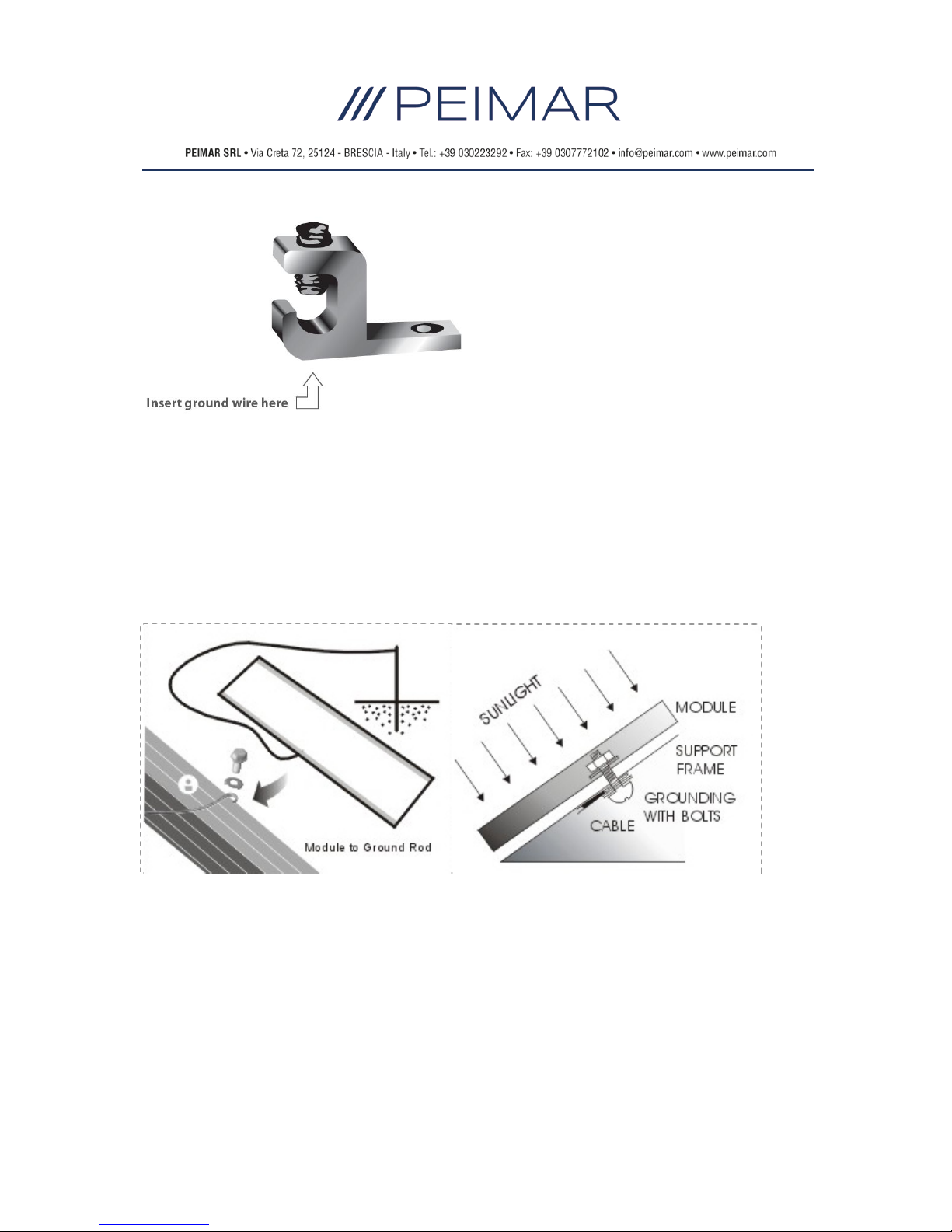
Check connections of cables, connectors, and grounding. Change modules must be the
same kind and type, if need. Modules can operate effectively without ever being washed,
although removal of dirt from the front glass can increase output. The glass can be
washed with a wet sponge or cloth, wear rubber gloves for electrical insulation.
VIII) SAFETY PRECAUTIONS
Module installation and operation should be performed by qualified personnel only.
Children should not be allowed near the solar electric installation.
Avoid electrical hazards when installing, wiring, operating and maintaining the module.
Modules produce DC electricity when exposed to light and therefore can produce an
electrical shock or burn. Modules produce voltage even when not connected to an
electrical circuit or load. Modules produce nearly full voltage when exposed to as little as
5% of full sunlight and both current and power increase with light intensity. Do not touch

INSTALLATION MANUAL GUIDE | DATE: 02/2017
11
live parts of cables and connectors. As an added precaution, use insulated tools and
rubber gloves when working with modules in sunlight.
Fall of modules from high place will cause death, injury or damage. Do not drop module
or allow objects to fall on module, never leave a module unsupported or unsecured. If a
module should fail, the glass can break a module with broken glass cannot be repaired
and must not be used.
When installing or working with module or wiring, cover module face completely with
opaque material to halt production of electricity. Modules have no on/off switch. Modules
when exposed to sunlight generate high voltage and are dangerous, modules can be
rendered inoperative only by removing them from sunlight, or by fully covering the front
surface with opaque cloth, cardboard, or other completely opaque material, or by working
with modules face down on a smooth, flat surface when installing or maintaining.
Do not artificially concentrate sunlight on the module.
Modules can produce higher output than the rated specifications. Industry standard
ratings are made at conditions of 1000W/m2and 25°C cell temperature. Reflection from
snow or water can increase sunlight and therefore boost current and power. In addition,
colder temperatures can substantially increase voltage and power.
Modules are intended for use in terrestrial applications only, thus excluding aerospace or
maritime conditions or use with sunlight concentration.
It is recommended that the module remains packed in the box until time of installation.
Work only under dry conditions, with a dry module and tools, since sparks may be
produced, do not install module where flammable gases or vapors are present.
Do not drill holes into module frame as it will void warranty. Modules are constructed
frame as it will void warranty.
Handled with care, if the front glass is broken or if the polymer backskin is tom, contact
with any module surface or the frame can produce electrical shock. Particularly when the
module is wet, broken or damaged modules must be disposed of properly. Do not
disassemble, bend, impact by sharp objects, walk on, and throw or drop etc. keep back
surface free from foreign objects.
Avoid sharp edges.
Use module for its intended function only follows all module manufacturers’ instructions.
Do not disassemble the module, or remove any part or label installed by the
manufacturer. Do not treat the back of the module with paint or adhesives.
If not otherwise specified, it is recommended that requirements of the latest local,
national or regional electrical codes be followed.
Retain this installation manual for future reference.
IX) NOTES
The electrical characteristics are within ±5 percent of the indicated values of Isc, Voc, and
Pmax under standard test conditions (irradiance of 100mW/cm2, AM 1.5 spectrum, and a
cell temperature of 25°C (77°F).

INSTALLATION MANUAL GUIDE | DATE: 02/2017
12
Under normal conditions, a photovoltaic module is likely to experience conditions that
produce more current and/or voltage than reported at standard test conditions.
Accordingly, the values of Isc and Voc marked on this module should be multiplied by a
factor of 1.25 when determining component voltage ratings, conductor capacities, fuse
sizes, and size of controls connected to the PV output.
Table of contents
Popular Solar Panel manuals by other brands

Your Solar Home
Your Solar Home SolarSheat installation guide

Uniteck
Uniteck UNIFIX 300 Assembly instruction

Sun-Tech
Sun-Tech STP200S-24/Ad+ installation guide

Qcells
Qcells Q.PEAK DUO-G5 series Installation and operation manual

CanadianSolar
CanadianSolar CS3U-350MB-AG installation manual

GOAL ZERO
GOAL ZERO NOMAD 200 quick start guide