Pelton & Crane Helios HL3S User manual

Installation Manual
Helios Light

TABLE OF CONTENTS
SyStem Overview ............................................................................................................................................................................................... 3
Safety NOteS ....................................................................................................................................................................................................... 5
ellipSe pOle iNStallatiON ............................................................................................................................................................................... 6
ellipSe heliOS iNStallatiON - pOle leveliNg adjuStmeNt .................................................................................................................. 7
Spirit ellipSe heliOS iNStallatiON —pOle leveliNg adjuStmeNt ..................................................................................................... 8
pmu heliOS pOle iNStallatiON........................................................................................................................................................................ 9
light iNStallatiON fOr pmu mOuNt ............................................................................................................................................................ 10
eNterpriSe - pmu mOuNt & alliaNCe (with CuSpidOr) ............................................................................................................................11
alliaNCe pmu mOuNt......................................................................................................................................................................................... 12
traCK & trOlley heliOS iNStallatiON ......................................................................................................................................................13-18
wall & CaBiNet mOuNt heliOS iNStallatiON............................................................................................................................................19-21
CeiliNg mOuNted heliOS iNStallatiON......................................................................................................................................................22-24
COlumN iNStall................................................................................................................................................................................................... 25
heliOS led uNit iNStall.................................................................................................................................................................................... 26
heliOS led uNit traNSfOrmer iNStall....................................................................................................................................................... 27
traNSfOrmer CONNeCtiON fOr 1700 ChairS ............................................................................................................................................ 28
heliOS quiCK CONNeCt remOval................................................................................................................................................................... 29
heliOS quiCK CONNeCt remOval, CONt’d ................................................................................................................................................... 30
maiNteNaNCe aNd adjuStmeNtS..................................................................................................................................................................31-33
eleCtriCal CONNeCtiONS CeiliNg, wall, traCK, CaBiNet ..................................................................................................................... 34
heliOS CheCKliSt ............................................................................................................................................................................................... 35
heliOS field retrOfit addeNdum................................................................................................................................................................. 36
heliOS upgrade KitS......................................................................................................................................................................................... 37
heliOS upgrade KitS......................................................................................................................................................................................... 38
iNStruCtiON fOr upgradiNg SyStem pOSt mOuNt (pmu) lightS with pOwer Supply iN BaSe Of Chair............................... 39
iNStruCtiON fOr upgradiNg SyStem ellipSe lightS with pOwer Supply iN juNCtiON BOx .................................................... 39
iNStruCtiON fOr upgradiNg SyStem pOSt mOuNt (pmu) lightS with pOwer Supply iN juNCtiON BOx................................ 40
heliOS traCK upgrade iNStruCtiONS ......................................................................................................................................................41-42
NOteS ..................................................................................................................................................................................................................... 44
Technical Support
Technical assistance is available Monday through Friday, Phone: 800-659-5922
8:00 am to 8:00 pm (Eastern Standard Time). Fax: 800-659-7255
Customer Service: 800-659-6560
WARNING: Only authorized service
technicians should attempt to service Pelton
& Crane Equipment. Use of other than
authorized technicians will void the warranty.
It is the user’s responsibility to read and understand the
contents of this manual. This manual contains impor-
tant information relative to hazards to personnel and
property if this equipment is not installed, used and/or
maintained as instructed.
WARNING: Federal law restricts this device
to sale by or on the order of a dentist.

3
053154 r17
SYSTEM OVERVIEW
Cabinet Mount
System Ellipse
Mount
System
Mount
Track Mount
Wall Mount
Ceiling
Mount
Unit
Mount
suitable for dentistry. The low voltage light source is mounted in various ways for allowing the user to adjust the position
to illuminate the oral cavity. The Helios Dental light is intended for use by dental professionals to illuminate the oral cavity
while performing examinations and dental procedures.
Model # HL3S
HLS
Model # HL3CB
HLCB
Model # HL3C
HLC
Model # HL3U
HLU
Model # HL3S
HLS
Model # HL3WL
HLWL
Model # HL3T
HLT
Track
Model # TH
TH1
--OR--

4053154 r17
Product Disposal
Contact your local authorized dealer for proper disposal of the
device to ensure compliance with your local environmental
regulations.
Interference with Electromedical Devices
To guarantee the operational safety of electromedical
devices, it is recommended that the operation of mobile radio
telephones in the medical practice or hospital be prohibited.
Strong EMI sources such as electro surgery units or x-ray units
may affect performance. If performance problems occur, move
the unit to another electrical circuit or physical location.
Incompatible Units or Accessories
Incompatible Units or Accessories: To guarantee the operational
safety and function of this device, the use of unapproved units
or accessories is not advised. Doing so could result in potential
hazard. Using accessory equipment not complying with the
equivalent safety requirements of this equipment may lead to
a reduced level of safety of the resulting system. Connecting
electrical equipment to multiple socket outlets effectively leads
to creating an ME SYSTEM, and can result in a reduced level of
IEC 60601-1-1 or IEC 60601-1:2005
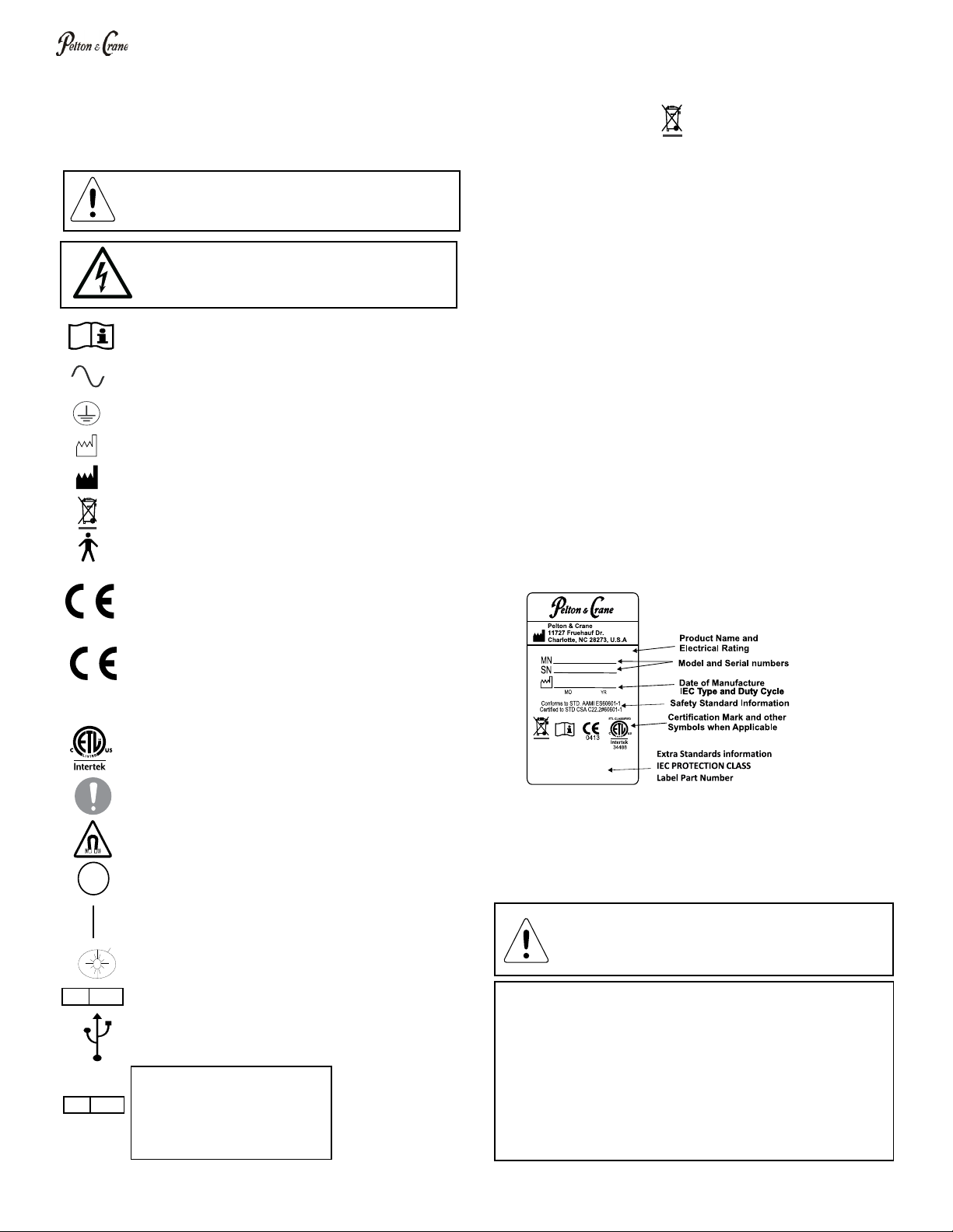
Product Identication
label states the unit model and serial number, electrical
the SAMPLE label shown below.
Working Environment
Recommended working condition is:
Ambient Temperature: 68°F to 76°F (20°C to 25°C)
Relative Humidity: 20% to 60% non-condensing
Atmospheric Pressure: 13.1 to 15.3 PSI (900 to 1060hPa)
GENERAL INFORMATION
Denition of Symbols
The following symbols and terms may be used throughout this
manual and your equipment:
WARNING: Failure to carefully follow the described
procedure may result in damage to the equipment
and/or injury to the patient/operator.
Risk of electrical shock present.
Make sure power is disconnected before
attempting this procedure.
See operating instructions.
(AC) Alternating current.
Protective earth (Ground)
Manufacturing Date
Waste Electrical and Electronic Equipment.
Type B Applied part.
Conforms with the Essential Requirements of the
European Medical Device Directive 93/42/EEC for
Class I Devices.
Conforms with the Essential Requirements of the
European Medical Device Directive 93/42/EEC for
Class IIa Devices.
Indicates conformity to General Requirements for
General mandatory action required, important to
Off
On
Light Switch
European Authorized Representative
USB Port
ETL CLASSIFIED
EC REP
Medical Device & QA Services Ltd.
76, Stockport Road,
Timperley.
Cheshire, WA15 7SN.
United Kingdom.
Tel: +44 (0) 845 527 5078 Fax: +44 (0) 161 903 9787
Email: info@ mdqas.com www.mdqas.com
EC REP
Medical Device & QA Services Ltd.
76, Stockport Road,
Timperley.
Cheshire, WA15 7SN.
United Kingdom.
Tel: +44 (0) 845 527 5078 Fax: +44 (0) 161 903 9787
Email: info@ mdqas.com www.mdqas.com
Authorized Representative:
Kaltenbach & Voigt GmbH
Bismarckring 39
88400 Biberach
Germany
0413
WARNING: It is not safe to use the unit where there
and heavy property damages
Manufacturing Place
Storage Conditions: The device is appropriately
packaged in a box. If product is to be stored before
installation, storage and handling instructions in the
packaging should be adhered to. Handling and storage
conditions are marked on the box.
Temperature: -4°F to 122°F/ -20°C to 50°C
Relative Humidity: 10% to 90%
If the device is not to be used for some time, ensure the
master switch is switched off.
DENTAL ___ __VAC__A__HZ

5
053154 r17
WARNING: Only authorized service
technicians should attempt to service
this equipment. Use of other than
authorized technicians will void the
warranty.
WARNING: Use a licensed electrician
for all wiring.
WARNING: Failure to disinfect
the dental operating light between
patients could expose user/patient to
cross contamination and bio-burden/
bio-contamination.
WARNING: To avoid risk of electric
shock, this equipment must be
connected only to supply mains with
protective earth.
WARNING:
equipment is allowed.
Electrical Specications
All fuses are labeled at point of use.
Replace fuses only with type and rating
as indicated.
Volts Cycles Amps
115 VAC 60 HZ 1 A ~
230 VAC 50 HZ .6 A ~
Type: B
Operation Mode: Continuous
Splash Protection: IPX0
WARNING: The Helios light is not to
be used in rooms where an explosion
hazard exists.
WARNING: Rotational stops are designed for a
maximum force limit of 25 lbs. If rotational stops
are broken, immediately take the equipment
out of use and have the equipment serviced.
Operation of damaged equipment could result in
injury to the operator and/or patient.
Storage Conditions:
-4°F to 122°F/ -20°C to 50°C
10% to 90% Relative Humidity
As manufacturers of electro-medical products we can assume responsibility for safety-related performance of the
this purpose, and if components affecting safe operation of the unit that may be needed are replaced with original parts.
SAFETY NOTES
WARNING: Failure to install set
screws & roll pin per Installation
Instructions could result in injury or
damage to equipment.
WARNING: Power cords and their associated
parts cannot be substituted without increased
use of Pelton & Crane replacement parts only!
personnel. Make sure all service loops, strain
reliefs, and cord guards are in place and that
line, neutral and ground wires are secured.
WARNING: This product must be disinfected
before use.

6053154 r17
ELLIPSE POLE INSTALLATION
Remove light from packaging
1. Apply grease to both sides of the two
needle bearings.
washer over the bottom. Repeat procedure
for other needle bearing.
3. Place centering washers onto top and
bottom of lower ellipse light post. Lower
pole mount as shown. Assemble lower
ellipse light post needle bearings, thrust
washers, unit arm washer, lock washer
and mounting bolt onto ellipse pole mount.
properly centered so that they won’t be
damaged during tightening of bolt.
4. Install lower ellipse pole mount to the
chair ellipse support plate (not shown) by
tightening mounting bolt to 26-30 lbs/ft with
a 15/16” torque wrench. Mounting bolt must
be tightened securely and give adequate
resistance through entire pole swing range
of motion.
5. Snap on cap over bolt head and unit arm
washer.
6. Feed power and signal cables from Flex
Arm into the upper pole.
pole long set screw (short set screw is
on opposite side of detent). Insert Flex
Arm into pole. Verify long set screw is still
aligned with detent and tighten both set
screws.
for left or right handed practitioners. If the
opposite hand is desired, switch long and
short set screws. Rotate detent to opposite
side and retighten set screws.
8. Take the plastic packaging sleeving from
the light pole, and use it to wrap around
around during the following assembly step).
9. Lift light and upper pole together, feed
wires into lower pole and insert upper pole
into lower pole. Pull out cables from other
end.
Upper Long
Set
Short
Flex Arm
Upper
Pole
Lower
Pole
Ground Screw
Ellipse Pole
Mount
Thrust Washer
Thrust Washer
Centering
Washer
Centering
Washer
Thrust Washer
*
*
Bearing
Thrust Washer
Cap
Mounting
Bolt Lock Washer
Unit Arm Washer

7
053154 r17
ELLIPSE HELIOS INSTALLATION - POLE LEVELING ADJUSTMENT
Set Screw
(B)
Set Screw
(A)
WARNING: Before making any connections,
be sure all power has been disconnected.
Making connections while chair or unit is
connected to power source may result in
equipment damage or injury.
Remove poles and arm from shipping box. Leave the
packing on vertical pole only.
2. Take the lower ellipse pole and insert bayonet end into
the chair mount until fully engaged (Figure 1). Set screws
should be seated in chair mount holes and lower ellipse
pole will be supported on its own.
3. Attach levels on vertical posts, 90 degrees apart so they
will measure front to rear leveling and side to side leveling.
Use a hex tool to adjust front set screw (A) to level the
posts from front to back (Figure 2). Adjust the side set
screws (B) to level the posts from front to rear. When the
post is level in both directions, tighten bolt (C) to secure
the unit to the chair mount (Figure 3) (Make sure pole is
still level after tightening bolt).
4. Remove all remaining packaging and inspect the light
for damage.
5. Loosen the screws and slide out the tubing cover from
the underside of the chair mount (Figure 4).
Set Screw
(A)
Chair Mount
Set Screw
(B)
Bolt (C)
Bayonet
Bolt (C)
Tubing Cover
Screws
Figure 1
Figure 2
Figure 3
Figure 4
WARNING: This line is intended for low
voltage use only. Use of this line is at the
discretion of the end user.

8053154 r17
SPIRIT ELLIPSE HELIOS INSTALLATION —POLE LEVELING ADJUSTMENT
6. Install supplied cable braid sleeving over cables.
7. Connect the light communication cable and low
voltage cables (Figure 5). These connections should
be made with their mating connectors. As with all
electrical connections, care should be taken for
proper alignment to prevent damage and ensure
proper electrical contact.
8. Connect ground wire to bayonet as illustrated
(Figure 5).
9. Once all connections are made, put on cable braid
sleeving over visible bundles and push any excess
lines and cables back into poles. Rotate ellipse poles
to their worst case position(s) and make sure cables
have enough slack to move properly with rotations.
10. Replace tubing cover and tighten the screws that
were loosened earlier (Figure 6).
Figure 5
Figure 6
1800/3000 Chair
1700 Chair
Screw
Tubing Cover
Helios Power
Cable
Helios Remote
Touchpad Cable
Ground Wire

9
053154 r17
Upper Long
Set
Short
PMU HELIOS POLE INSTALLATION
1. Remove lights from packaging. Feed cables into pole.
arm into pole. Verify long set screw is still aligned with
detent and tighten both pole set screws.
handed practitioners. If the opposite hand is desired,
switch long and short set screws, rotate detent to
opposite side and retighten set screws.
3. Take the plastic packaging sleeving from the light pole
around during the following assembly steps).
Install
Shroud
4. Install Dress Ring in proper orientation over
bottom of light pole.
5. Lift light and pole together and feed wires into
PMU and insert light pole in middle position. For
1500 PMU only: Slide washer onto the bottom
of the pole and install locking ring.
6. Make connections to moving cables inside
PMU.
7. Remove plastic packaging sleeving.
installation. Check light for operation.

10 053154 r17
LIGHT INSTALLATION FOR PMU MOUNT
For 1500 PMU
1. Locate and unpack upper light pole and light arm
assembly. Have an assistant hold upper pole in place and
route light cable through upper pole as shown. Install light
arm assembly into top of upper pole.
2. Ensure that the Dress Ring is assembled on the pole
3. Insert pole into the center hole of the PMU.
4. Slide washer onto the bottom of the pole and install
locking ring.
5. Connect wiring inside the PMU
For 3000 PMU
1. Ensure that the Dress Ring is assembled on the pole.
2. Insert the pole into the center hole of the PMU
3. Connect wiring inside the PMU
Dress Ring
Washer
Retaining Ring
}1500 pmu ONly

11
053154 r17
1. Prepare the light-post clamp for installation by
removing the two 5/16” hex-head bolts and separating
the two halves.
2. Remove the side panel from the PMU to gain access
to the inside of the unit.
of an assistant.
3. Position the post clamp assembly over the unit pole.
Line up the channel in the clamp assembly with the
machined hole in the unit pole so the light cord will
be able to pass through it without exiting the clamp
assembly.
4. Place the light post stub into the open half of the post
clamp taking care not to cover the channel that the
cord will pass through. Tighten both 5/16 bolts.
5. Place the light post onto the stub.
6. Route the light cord through the channel and into the
unit pole. The cord will exit the unit pole inside the
utility center.
7. Replace the side panel onto the PMU
See Maintenance & Adjustments for nal
installation; Check Light for Operation.
ENTERPRISE - PMU MOUNT & ALLIANCE (WITH CUSPIDOR)
Stub

12 053154 r17
1. Unpack the light and related components from the
packaging.
2. Remove the side panel from the PMU to gain
access to the inside of the unit.
3. Insert the mounting pole into the center hole in the
PMU mount. Lift the PMU top cover to gain access
to the two set screws located in the side of the PMU
mount. Securely tighten both set screws to lock the
mounting pole into the PMU mount. Lower the PMU
top cover back into its original positon.
4. Install the stub into the mounting pole. Install the
boot and collar over the mounting pole and push them
down until the boot rests upon the PMU top cover.
5. Install the plastic washer onto the stub and push
down until it rests upon the top of the mounting pole.
pole: Feed the cables from the light through from the
top end of the light pole until they exit from the bottom
hub with the long set screw in the light pole (the short
into the top end of the light pole. Verify the long set
screw is still aligned with the detent and tighten both
set screws.
7. Take the plastic packaging sleeving from the light
pole and use it to wrap around and tie together the
swinging around during the following assembly steps.
8. Lift the light and light pole together and feed the
cables down through the stub and mounting pole and
into the PMU, then slide the bottom of the light pole
over the stub and push it down until the bottom of the
pole rests upon the previously installed plastic washer.
9. Connect the cables to the corresponding cables
inside the PMU.
10. Remove the plastic packaging sleeving.
11. Replace the side panel onto the PMU.
Light/ Flex Arm
Assembly
Light Pole
Plastic
Washer
Collar
Boot
Stub
Mounting
Pole
Set
Screws
ALLIANCE PMU MOUNT
(withOut CuSpidOr)

13
053154 r17
Pre-Installation of Electrical Wiring
1. Stub out a 115 VAC, 60 Hz (or 230 VAC 5DHZ) electrical supply. See
position of transformer box. Protect circuit with an appropriate fuse or
circuit breaker.
2. Stub out wiring 39-3/16” (99.5 cm) from the chair center line along the
long axis of the track and trolley assembly.
NOTE: For electrical supply connection, use wiring suitable for at least
90°C (194°F).
NOTE: The maximum ceiling height the light may be mounted to is 10 ft.
3. Ensure green/yellow ground wire is grounded at ground screw.
4. Install wall switch between power supply and light power supply
transformer. This provides for safety and convenience during installation
or service. Wall switch can be switched OFF during electrical storms to
prevent transformer damage caused by voltage overloads. Wire nuts are
furnished.
* If installing a monitor, See Monitor Installation Manual for correct ceiling
height.
TRACK & TROLLEY HELIOS INSTALLATION
WARNING:
electrician.

14 053154 r17
TRACK & TROLLEY HELIOS INSTALLATION
1. The track and trolley are shipped completely
assembled. The track channel (A) is mounted to a
pallet. Two extrusion panels (D), two dress covers
(E), two end caps (F) and Light trolley (G) are
attached to the channel.
2. To reach the eight 17/64” (7mm) diameter pre-
drilled mounting holes (H) (see next page) in the
plywood pallet (C), detach the two end caps (F) by
removing two #10 -24 x 1/2” round head screws
(I) from each end. Set end caps and screws aside.
Remove transformer cover (X) from track.
3. Remove two #8 x 3/4” pan head slotted sheet metal
screws (J) from each dress cover. Lift away dress
covers. Set aside the screws.
Side Stops
5(K)
Track Channel
1(A)
Extrusion
Panels
1(D)
Trolley
1&5(G)
Dress
Cover
1(E)
Dress
Cover
1(E)
(2) #10 x ½"
Round
Head Scre
ws
2(I)
(2) #8 x 3/4"
PH Slotted
Screws
3(J)
End Cap
1(F)
End Cap
1(F)
Side Stops
(L)
Power
Cord
(underneath trolley)
(M)
(2) #8 x 3/4"
PH Slotted
Screws
4(J)
Cover(X)
4. Identify the eight 17/64” (7mm) diameter pre-drilled
mounting holes (H) in plywood pallet (C) on next page.
5. For easier installation, detach the trolley (G) from the
channel before mounting the pallet.
Remove the two stops (K) from the end of the track
channel opposite the transformer box.
NOTE:L).
Disconnect power cord (M) at trolley bracket leaving cord
intact under extrusion panel (D). Remove trolley off of
track. Set aside.

15
053154 r17
2-13/16"
21-5/16"
42-11/16"
64"
76-13/16"
P
allet
8-1/2"
10"
11/16"
Mounting
Holes
2 & 4(H)
Ø 17/64"
Pallet
2&4 (C)
TRACK & TROLLEY HELIOS INSTALLATION
1/4" Dia. X 4" Long
Lag Bolt for
mounting holes
(Not Furnished)
31" (78.7 cm) 33" (83.8 cm)
5/16" (.79 cm)
Holes- 8 places
1-13/16"
(4.6 cm)
39-3/16" (99.5 cm)
64" (162.6 cm)
76-13/16" (195.1 cm)
8-1/2"
(21.59 cm)
5"
8-3/16"
(20.8 cm)
10"
(25.4 cm)
C
Lof Chair

16 053154 r17
8-1/2"
(21.59 cm)
60" (152.4cm)
Min.
64" (162.6 cm)
Max.
Parallel Wood Joists
Bracing added by contractor
*Optional Monitor Mount
8 x 5/16” Holes
Track Framing and Trolley Installation
Mounting Pallet to Perpendicular Wood Joists
live load.
* If a monitor is being installed with a light, consult monitor literature.
7. Using eight pre-drilled holes in plywood pallet (3/4” x 10” x 76-13/16”) mount to perpendicular
wood joists with eight 1/4” x 4” lag bolts.
NOTE: Drill additional holes if necessary. Ensure mounting pallet is level.
TRACK & TROLLEY HELIOS INSTALLATION
Mounting Pallet to Parallel Wood Joists
to support approximately 200 pounds (100kg) live load.
9. Using eight pre-drilled holes in mounting pallet mount to cross bracing with eight 1/4” x 4” lag screws.
10. Reinstall Trolley on Track, plug in power cable and reinstall side stops (shown on page 12).
NOTE: Drill additional holes if necessary. Ensure mounting pallet is level.
60" (152.4cm)
Min.
64" (162.6 cm)
Max.
8-1/2"
(21.59 cm)
Perpendicular Wood Joists
*Optional Monitor Mount
Facility needs to provide adequate framing to support at least 200
pounds (100kg) live load.
For ceilings constructed using wood joist, the mounting pallet must bolt
directly to the ceiling joists and additional framing or cross blocking using
the provided hardware (refer to page 12 for pallet installation).
For other types of ceiling construction, such as suspended ceilings, it will
be necessary for installer to provide adequate framing to support at least
200 pounds (100kg) live load that will be secured to ceiling structure
before attaching the mounting pallet to framing.
If the mounting pallet is bolted to concrete or metal, the installer must
provide the necessary bolts, anchors and washers to secure it to the
ceiling structure.
WARNING: It is the responsibility
of the dealer/contractor to provide
suitable support framing prior to
installation.

17
053154 r17
2
2
1
Power
TRACK & TROLLEY HELIOS INSTALLATION
5/8" depth
1/8” Drill Bit with Stop
WARNING: Set screws must be tightened
securely and roll pins must be installed to
prevent column from unscrewing during
operation. Failure to install roll pins and tighten
set screws securely could result in light falling
off trolley.
NOTE: Ensure column is plumb to
prevent trolley from drifting. Adjust pallet
with shims if necessary.
Magnalube
2
WARNING: Failure to use the supplied drill bit
with stop to control depth of drill bit may result
in electrical wiring damage and subsequent
electrical shock.
NOTE: For quick connect removal see pages 26-27

18 053154 r17
Track Light installation (See page 13 for Illustration)
1. Remove the adapter from the column and set
aside.
2. Feed power cable from trolley through the column.
Apply grease (*) to threads on column. Thread
column onto trolley.
3. Insert and tighten two set screws (found within the
hardware kit sent inside the column) in trolley to
secure column.
4. Using 5/64 Allen Wrench, loosen the two upper set
screws on adapter.
5. Apply grease (*) to threads on column. Thread
Adapter onto Column and apply Magnalube grease
(*) to stem.
6. Connect wire from Trolley to wire in Flex Arm, push
the QC Collar to the installation position and install
Stem into Knuckle while pushing wires into Column.
TRACK & TROLLEY HELIOS INSTALLATION
knuckle) with vertical alignment sticker on hub.
two clamps in the Knuckle snap into place in the
groove on the Stem. Pull the QC Collar to the
locked position (it must fully cover the clamps in
the Knuckle).
8. Ensure rotational stop is in correct position, and
tighten set screws on adapter.
9. Locate two 3/32” pilot holes on the trolley and the
adapter; using the supplied drill bit with stop, drill
1/8” hole to a depth of 5/8”. Insert roll pins (found
within the hardware kit sent inside the column).
Check Light for Operation.
Upper
Position
Lower
Position
C
L
'A'
64”
81-1/4”
FLOOR
LIGHT
CEILING
'B'
350°
Ceiling
Height from
Floor
Column Set
Assy. (P/N)
"B" & "C"
Column
Length
Column
Assy (P/N)
'A' 'B'
8' (96") 053933 14" 3324030GY
8-1/2' (102") 053934 20" 016919GY
9' (108") 053935 26" 016920GY
9-1/2' (114")
053937 38" 016922GY
Ceiling Height Helios Flex Arm
016921GY
32"053936
10' (120")
Minimum ceiling height is 96"
FLOOR
37”
23”
120°
330°
22”
32-3/4”
28”

19
053154 r17
Rotational
Stop Clamp
NOTE: The wallboard is drilled to
mount on 16” centers. Locate two
studs and mark the locations.
WALL & CABINET MOUNT HELIOS INSTALLATION
WARNING: Use a
licensed electrician for
all wiring.
4
6
6
7
Embed Screw at
least 2-1/2" (6.4 cm)
into wood
2-1/2"
(6.4cm)
1/4"
(.63cm deep)
3/4" (1.9 cm)
17/64" (.57 cm) dia.
8
9
6

20 053154 r17
Provide adequate framing to support approximately 200 pounds live load. Framing should allow all four
mounting bolts to enter solid wood.
Provide a 1.0 amp, 115VAC, 60HZ supply and protect it with a 15 amp fuse or breaker.
Install wall switch between power supply and light power supply transformer. This provides for safety and
convenience during installation and service. Wall switch can be switched OFF during electrical storms to
prevent transformer damage caused by voltage overloads. Wire nuts are furnished.
WALL & CABINET MOUNT HELIOS INSTALLATION
NOTE: Steps 1 through 4 are for Wallboard
Installation only:
1. Position wallboard over the located studs with the
2. Position a level over wallboard. Using the
centerlines, verify that marks are level. Mark holes
using an awl or scribe by piercing the wall through
the hole.
3. Drill pilot holes 1/4” diameter in the wall at the
marked position.
4. Insert the four 3/8” lag bolts into the concave
concave depression on the washer. Mount the
wallboard with the lag bolts and snap the bolt
5. Connect the power supply to the transformer
terminal strip, line, neutral and ground.
Wall & Cabinet:
6. Locate the mounting bracket. Line up holes in the
bracket with the holes drilled in the cabinet wall.
Install transformer mounting bracket using the
four 1/4-20” bolts and washers making sure the
mounting bracket is level.
NOTE: If ceiling clearance is less than 104”, slide the
Pole into the Mounting Bracket before fastening
Mounting Bracket to structural channel.
7. Place nylon washer and rotation stop clamp on pole
(mount end) and install pole pivot adapter into the
mounting bracket.
8. If required, turn the adapter so the rotational stop
feature on the stem assembly is turned toward the
head of the chair the light is being installed onto.
9. Install the locking key and secure it with the locking
screw.
23” 37”
Lower Position
Upper Position
C
L
Wall Delivery
Wall Mounting Board
56-1/2”
78-1/2”
89-1/4”
3”
93”
60”
60”
77”
16”
16”
8”
FLOOR
LIGHT
120°
350°
C
L
CHAIR
WALL
WALL
330°
22”
53-1/2”
FLOOR
28”
This manual suits for next models
9
Table of contents
Other Pelton & Crane Dental Equipment manuals

Pelton & Crane
Pelton & Crane Spirit 1700 SII User manual

Pelton & Crane
Pelton & Crane Spirit 1800 Series User manual

Pelton & Crane
Pelton & Crane 1500 User manual

Pelton & Crane
Pelton & Crane Centennial RD36 Owner's manual

Pelton & Crane
Pelton & Crane Spirit 3000 Series User manual

Pelton & Crane
Pelton & Crane Spirit 3300 Series User manual

Pelton & Crane
Pelton & Crane SPIRIT 3000 ELECTROTORQUE-TLC User manual