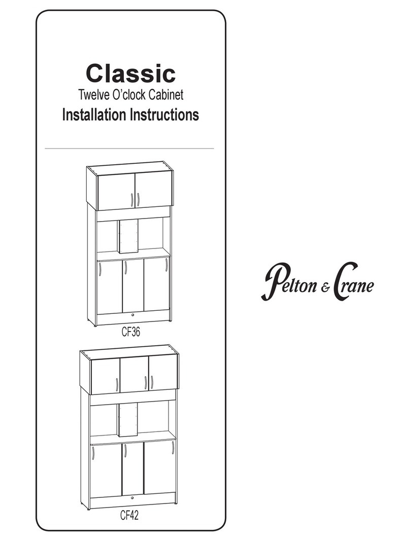
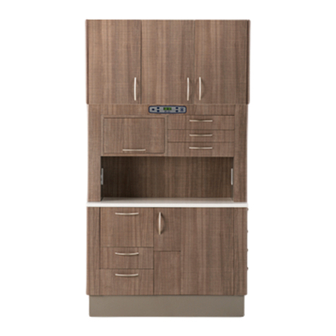
Pelton & Crane Caseworx SIDE CABINET Installation guide

SIDE CABINET AND
MILLENIUM
CABINET
Use & Care
-AND-
Installation Instructions
Caseworx

2049336 R02
Technical Support
Technical assistance is available Monday through Friday, Phone: 800-659-5922
8:00 am to 8:00 pm (Eastern Standard Time). Fax: 800-659-7255
Customer Service: 800-659-6560
All registered trademarks are the property of their respective owners.
TABLE OF CONTENTS
OVERVIEW ..............................................................................................................................................................................................................3-4
SS OVERVIEW ........................................................................................................................................................................................................ 5
SD OVERVIEW ......................................................................................................................................................................................................... 6
PREPaRIng thE SItE............................................................................................................................................................................................7-8
UPPER MODULE InStaLLatIOn..........................................................................................................................................................................9-11
CaBInEt InStaLLatIOn......................................................................................................................................................................................12-15
MILLEnnIUM REaR COLUMn InStaLLatIOn...................................................................................................................................................... 15
DOOR & DRaWER aDjUStMEnt.......................................................................................................................................................................... 16
taPMaStER FaUCEt SERVICE InFORMatIOn .................................................................................................................................................. 17
CLEanIng, DISInFECtIng & StERILIZatIOn..................................................................................................................................................... 18
CLEanIng CaBInEtRY SURFaCES ..................................................................................................................................................................... 19
DIMEnSIOnaL Data DRaWIngS ........................................................................................................................................................................20-21
InStaLLatIOn anD SERVICIng ChECkLISt ...................................................................................................................................................... 22
nOtES ..................................................................................................................................................................................................................... 23

3049336 R02
OVERVIEW
Charlotte NC, U.S.A.28273,
11727 Fruehauf Dr.
MN
SN
MO
YR
120VAC, 12A, 60Hz
OPERATORY CABINET
34488
ETL CLASSIFIED
Product Name and
Electrical Rating
Model and Serial numbers
Date of Manufacture
IEC Type and Class
Safety Standard Information
Certification Mark and other
Symbols when Applicable
046820 Rev. 04 08/07/13
PRODUCT DISPOSAL
Contact your local authorized dealer for proper disposal
of the device to ensure compliance with your local
environmental regulations.
INTERFERENCE WITH ELECTROMEDICAL DEVICES
To guarantee the operational safety of electromedical
devices, it is recommended that the operation of mobile
radio telephones in the medical practice or hospital be
prohibited.
Strong EMI sources such as electro surgery units or x-ray
units may affect performance. If performance problems
occur, move the unit to another electrical circuit or physical
location.
INCOMPATIBLE UNITS OR ACCESSORIES
To guarantee the operational safety and function of this
device, the use of unapproved units or accessories is not
advised. Doing so could result in potential hazard. Using
accessory equipment not complying with the equivalent
safety requirement of this equipment may lead to a
reduced level of safety of the resulting system. Connecting
electrical equipment to multiple socket outlets effectively
leads to creating an ME SYSTEM, and can result in a
reduced level of safety. All congurations shall comply with
the system standard IEC 60601-1-1 or IEC 60601-1:2005.
PRODUCT IDENTIFICATION
This product can be identied by its product label. This
label states the unit model and serial number, electrical
specications, manufacture date and safety classication.
Note the SAMPLE labels shown below.
DEFINITION OF SYMBOLS
The following symbols and terms may be used throughout
this manual and your equipment:
WARNING: Failure to carefully follow the
described procedure may result in damage
to the equipment and/or injury to the patient/
operator.
Risk of electrical shock present.
Make sure power is disconnected before
attempting this procedure.
See operating instructions.
(AC) Alternating current.
Protective earth (Ground)
Manufacturing Date
Waste Electrical and Electronic Equipment.
Type B Applied part.
Indicates conformity to General Requirements for
Safety is certied by Intertek Testing Services.
General mandatory action required, important to
follow instruction. Not a caution.
Warning, strong magnetic eld.
Off
On
Light Switch
Authorized Representative:
Medical Device and QA Services (MDQAS)
Spring Court, Spring Road, HALE, Cheshire, WA14 2UQ
United Kingdom
Tel: +44 (0) 845 527 5078 FAX: +44(0) 161 903 9787
WORKING ENVIRONMENT:
The unit is to be used in an ofce environment only
Ambient Temperature: 68°F to 76°F (20°C to 25°C)
Relative Humidity: 20% to 60% non-condensing
Atmospheric Pressure: 13.1 to 15.3 PSI (900 to 1050hPa)
STORAGE AND TRANSPORTATION
Temperature : -68°F to 122°F (-55°C to 50°C)
Relative Humidity : 10% to 90% non-condensing
LONG PERIODS OF NON-USE
If the device is not to be used for sometime, ensure the
water line is disinfected and ushed with air before the
master switch is switched off.
Technical Description
Model Designation: Caseworx Side Cabinet
Power Supply: 120V-50-60HZ, 12A
Protection against harmful ingress of water:
Ordinary Equipment
Mode of Operation: Continuous

4049336 R02
OVERVIEW
This cabinet is not used in rooms where an explosion hazard exists.
As the manufacturer of cabinetry, we can only assume responsibility from the safety related performance of the cabinet, if maintenance and repair are
carried out by the manufacturer, or by agencies authorized by Pelton & Crane for this purpose, and if needed components affecting the safety of the ap-
pliance are replaced exclusively by original spare parts.
We suggest that you request a certicate stating the type and extent of the work performed, from those performing such work, if necessary, stating any
alterations of the rated parameters or operating ranges, as well as date, name of organization and signature.
This type of appliance is classied to UL 60601-1, EN 60601-1, certied to CSA C22.2 No. 601.1-M90. Due to legal regulations, alterations of the
cabinet, which could impair the safety of the operator, patient, or third parties, are not lawful. For reasons of product safety, only original Pelton & Crane
accessories approved for this product, or accessories by third parties, which have been approved by Pelton & Crane, may be used. Using non-approved
accessories is at the risk of the user.
In order to prevent injury to persons and damage to the equipment, you must also read the warning and safety notes given in this User’s Manual. These
are emphasized with WARNING, CAUTION and NOTE.
Thank you for purchasing your new cabinet. It is engineered to provide many years of reliable performance. However, a certain
amount of care is required. Conscientious adherence to the Maintenance Instructions will ensure that your unit will function to your
satisfaction for many years to come. Therefore, we have provided you with a set of technical literature, which may be kept for quick
and easy reference.
In order to protect your rights under the warranty, the purchaser must register the unit by lling in the warranty information provided.
Safety Notes
Use only Pelton and Crane replacement parts.
All repairs should be performed by authorized
Pelton & Crane Dealer/ or their representatives.
WARNING: Only properly trained and authorized
service technicians should install and/or attempt
to service this equipment. Use of other than
authorized technicians will void the warranty.
WARNING: This cabinet is not for use in rooms
where an explosive hazard exists.
WARNING: No unauthorized modication of
this equipment is allowed.
WARNING: To avoid risk of electric shock, this
equipment must be connected only to supply mains
with protective earth.
As manufacturers of electro-medical products we can assume responsibility for safety-related performance of the
equipment only if maintenance, repair and modications are carried out only by Pelton & Crane or agencies we have
authorized for this purpose, and if components affecting safe operation of the unit that may be needed are replaced with
original parts.
We suggest that you request a certicate showing the nature and extent of the work performed, from those who carry
out such work, and specify that the certicate show any changes in rated parameters or working ranges, as well as the
date, the name of the rm and a signature.
Review the safety warnings and instructions before using the device to avoid injury and to prevent damage to this
equipment. The manufacturer’s liability is applicable only if the device is used in compliance with the directions
and safety warnings provided in this manual.

5049336 R02
G
D H
F
E
I
C
B
A
SS OVERVIEW
A, sink and waste module
B-C, storage module
D, sink
E, counter top
F, waste container
G, faucet
H, soap dispenser
I, contour module
The SS cabinet provides a work surface and storage. It is designed with the Dentist and staff in mind to provide a robust working
environment for the daily activities of performing dentistry. This product is intended for use by dental professionals.

6049336 R02
SD OVERVIEW
A, sink and waste module
B-C, unit mount area
D, sink
E, counter top
F, waste container
G, faucet
H, soap dispenser
I, contour module
DH
F
G
I
E
A
B
C
The SD cabinet provides a work surface, storage, and can be installed with or without a Pelton & Crane delivery
system. The SD cabinet is designed with the Dentist and staff in mind to provide a robust working environment for
the daily activities of performing dentistry. This product is intended for use by dental professionals.

7049336 R02
PREPARING THE SITE
Floor Template (M-SS150-3 Shown)
WARNING: Always lift cabinets by bottom edge, being careful to lift with your legs and not your back.
WARNING: Make all required, air water and drain attachments from the utilities to the incoming stub-up
connections before the delivery system installation occurs. Doing so prevents damage to the utility lines
from heat associated with some plumbing connection methods.
WARNING: Turn main power OFF at the installation site.
NOTE: Use oor template to locate utilities in relation to the dental chair. Because of varying city plumbing and
electrical codes, the dealer should ensure that installation meets local requirements. Pelton & Crane
can not be responsible for an installation which does not meet local plumbing and electrical codes.
Select the location for cabinet that will meet the operator’s arm reach and storage requirements. Refer to
the dimensional drawings while considering the location of air, water and electrical connections.
SPECIFICATIONS (Floor Template depicted in Illustration)
Air & Water Shut-off Valves (If required for delivery) : 1/2” pipe N.P.T. (supplied by the contractor) pro-
truding 1” from oor or wall. Manual shut-off valve supplied by the dealer to be installed by the contractor.
Maximum height can not exceed 5” when valves are fully opened.
Electrical: 1/2” conduit and quad box or equal junction (supplied by the contractor). Wire box as per
code with top of the box no higher than 4 1/2” above nished oor.
Voltage:
120 Volts AC, 3 wire, 15 amp circuit.
Central Vacuum (if required): Plumbing should be specied and terminated in treatment column with
5/8” OD tube perpendicular to oor, similar to drain connection.

8049336 R02
PREPARING THE SITE
1. Lay installation template over plumbing stub-ups and check the distance from the cabinet to the walls
according to operatory layout. (Generic oor template and wall template are depicted in illustration. Electrical
and plumbing templates for standard cabinets may be furnished on request.)
2. The shut-off valves for air and water must be installed above the nished surface as indicated in the
template: 5” max. when in an open position.
3. Install air and water shut-off valves. (Not Supplied)
NOTE: A 3/8” compression tting is recommended for the output connection on the cutoff valves.
4. Connect exible hoses from air and water regulator assemblies to the air and water shut-off valves.
NOTE: The template illustration depicts the mounting points.
WARNING: To ensure the proper operation of units and water ow devices ush all air and water
lines before connecting equipment.
For Millenium Rear Cabinets only: Mark the four cabinet mounting points according to the oor template. If the
cabinet will have a 2800 unit attached, mark the four additional mounting points indicated on the oor template.
Wall Template
9 o’clock 3 o’ clock

9049336 R02
Install E-Z Toggle:
A. Place #2 phillips head or cordless screwdriver into the recess of the E-Z toggle. Press rmly
into the wallboard and turn the anchor clockwise until seated ush with the wall, repeat for all
toggle bolt locations required. Make sure arrow on E-Z toggle is either pointing up or down.
(Figure 2)
B. From center, place hanging rail and washer into position over installed E-Z toggle. Insert
screw with the special point (#8 diameter with 2-1/8” length). (Figure 3)
C. With screw inserted into E-Z toggle, begin turning to engage clamp. Do not use power driver
to engage clamp. (Figure 4)
D. Continue turning screw until tight, the clamp will move forward against the drywall as the
screw is turned. Repeat for all toggle locations. (Figure 5)
WARNING: Upper cabinets should only be mounted by following the instructions in this manual and
using the hanging rail system provided with your cabinet. Do not attempt to hang cabinets via screws
through the back panel.
1. Determine the height to the top of the upper cabinet and mark location on the wall. (Figure 1)
•72” height is recommended for Treatment/Hygiene rooms (18.7” between countertop and upper cabinet).
•For Millennium Rear cabinets, use the Dimensional Data Drawings at the back of this manual to determine the appropriate
height. It may be preferable to install the base module and column rst to ensure proper upper height. If so, follow instruc
tions for Cabinet Installation rst, then return to these instructions to hang the upper.
•Space between the top of the cabinet and the ceiling should be at least 1-1/2” to allow full adjustment of
cabinet
2. Measure 1-3/4” down from the top elevation and mark a level line. This will be the location of the hanging rail.
3. Along marked level line, locate and mark studs in wall. Place hanging rail to level line and using screw holes in
the hanging rail as a template, mark locations (4) for toggle bolts between studs and at either end of the hanging rail.
(Figure 1)
4. Remove hanging rail and install E-Z toggle bolts in marked locations. Screw hanging rail to the wall.
UPPER MODULE INSTALLATION

10 049336 R02
5. Install 3” pan head screw with washer into each stud behind the hanging rail.
6. Prepare the cabinets for hanging. We suggest removing the cabinet doors and shelves
before hanging. The hinges are ‘snap-on/off’ and can easily be removed by pulling the
tab marked “pull” located at the back end of the hinge baseplate. Hold onto door securely
because the hinges disengage quickly when the tab is pulled. Preposition the hanger
bracket arm by turning the adjusting screw: grasp the hanger arm and pull out as you turn
the adjusting screw located in the front of hanger hardware. Otherwise you can turn the
screw and nothing appears to be happening. Turn the bottom screw counter clockwise
until the arm is fully extended. (Figure 6)
7. Hang each cabinet, making sure that the wall brackets are hooked onto the hanging
rail properly. Do not do any nal adjusting until all cabinets are hung. (Figures 7A + 7B)
UPPER MODULE INSTALLATION
8.Using the 5mm diameter x 30mm long sleeve and 4mm
diameter joining screw, secure unit together. Push sleeve
into system hole until it is ush with cabinet. From opposite
side, install fastening screw into the sleeve to draw cabinets
together (Figure 8)
Fastening locations:
Use the system holes directly behind the hinge base plates
on the front of the cabinet and the back bottom
and top system holes in the back of the cabinet. Figure 8
Figure 7A
Figure 7B
Cam wing mounting plate
One piece wing plate
Range (5/32")
Range (5/32")
Rotate front screw to increase or
decrease door position.
Range (3/32")
Rotate spiral -tech cam
screw to adjust door position.
Range (3/16")
over-adjusting hinges can cause damage
Note:
Upper & lower plates
must be moved
together for each door
Note:
Upper & lower plates
must be moved
together for each door
Drawer front adjustment - Standard
Ve rtical Adjustment
4.
5. Turn clockwise to raise-
counter clockwise to lower,
re-tightenAttachment Screw.
Loosen Attachment Screw
6. Tilt adjustment
(for large drawers only)
Horizontal Adjustment
1. Loosen Mounting Screws
2. Adjust Front
3. Tighten Screws
1
2/3.
4.
5.
6.
1.
Cam Screw
WARNING:
Drawer Adjustments
1. Vertical adjustment:
Loosen screws 2 lightly, adjust screw
1(adjustment ±2mm), tighten screws 2.
2. Horizontal adjustment:
Loosen screws 2lightly, adjust front
to desired position (adjustment 1.5mm),
tighten screws 2. .
3. Angle correction:
Loosen top screw or bottom screw
2according to your needs. Push angle
correction wedge
2tighten screws and tear off wedge.
Angle correction ±1.
(type 6155) in between,
A
Figure 6B

11049336 R02
Adjustments:
Side-to-side: adjustment is unlimited along the length of the rail.
Height adjustment: up or down 1-1/4”. Turn screw A clockwise to raise the
cabinet and counter clockwise
to lower the cabinet. (Figure 9C)
Depth adjustment: in or out 1-3/16”. Turn screw B clockwise to pull the
cabinet towards the wall and counter
clockwise to move the cabinet away from the wall.
9. The cabinets can now be adjusted using the adjusting screws on the
hanger hardware, and up or down until level and plumb. Start by adjusting
bottom screw A clockwise untilcabinets are pulled rm against wall. After all
cabinets are rm against wall, adjust cabinets until level using top screw B.
10. Replace doors and adjust if necessary. (Figure 10)
Hinge Adjustments
1. Side Adjustment
2. Height Adjustment
3. Depth Adjustment
UPPER MODULE INSTALLATION
1
2
3
Figure 9C
Figure 10

12 049336 R02
1. Remove packaging from side cabinet. Before installing the side cabinet inspect the cabinet for damage and verify that
all items on the quick install package checklist are in the packaging. Remove drawers and unclip doors. Set aside in a
safe area until they are to be reinstalled.
2. Remove screws and boards in subbase section securing the side cabinet to the pallet. Carefully lift and slide side the
cabinet off the pallet and into position. ALWAYS lift the cabinet by the bottom edge, being careful to lift with your legs and
not your back.
CABINET INSTALLATION

13049336 R02
CABINET INSTALLATION
4. Measure down 1-1/2” from the inside of the module top and fasten the cabinet to the wall with (2) 2-1/2” #10 screws as
shown.
3. Using a level on the counter top, level the side cabinet using the leveling feet as shown. Re-install false bot-
toms after leveling feet.
For Millennium Rear Cabinets only: Secure the cabinet to the oor using the appropriate fastener.
Concrete Floor: Four 1/2” x 4-1/4” anchors, square washers and nuts (located in supplied hardware
Wood oor: Four 1/2 x 41/2” lag bolts, square washers and lock washers.
False
Bottoms
Install (2) 2-1/2” #10 screws
Leveling
Feet Leveling Feet
Leveling Countertop

14 049336 R02
CABINET INSTALLATION
5. If backsplash is seperate from the cabinet, install the back splash against the wall and top of the countertop
using the clear silicone provided.
6. Install the water faucet and soap dispenser into the module top according to the manufacturer’s installation
instructions
7. Connect the side cabinet plumbing according to local codes and test.

15049336 R02
8. Re-install doors removed previously, taking care to place them in their original positions. Adjust hinges as needed.
CABINET INSTALLATION
1.Remove the front panel from the wire chase column. Set
aside in a safe area until it is to be reinstalled.
2.Align the column so that it is centered on the base mod-
ule. Fasten the column through the back panel into the wall
using screws (provided).
3.Reattach the front panel on the column.
MILLENNIUM REAR COLUMN INSTALLATION

16 049336 R02
DOOR & DRAWER ADJUSTMENT
Cam wing mounting plate
One piece wing plate
Range (5/32")
Range (5/32")
Rotate front screw to increase or
decrease door position.
Range (3/32")
Rotate spiral -tech cam
screw to adjust door position.
Range (3/16")
over-adjusting hinges can cause damage
Note:
Upper & lower plates
must be moved
together for each door
Note:
Upper & lower plates
must be moved
together for each door
Drawer front adjustment - Standard
Ve rtical Adjustment
4.
5. Turn clockwise to raise-
counter clockwise to lower,
re-tightenAttachment Scre
w.
Loosen Attachment Screw
6. Tilt adjustment
(for large drawers only)
Horizontal Adjustment
1. Loosen Mounting Screws
2. Adjust Front
3. Tighten Screws
1
2/3.
4.
5.
6.
1.
Cam Screw
WARNING:
Drawer Adjustments
1. Vertical adjustment:
Loosen screws 2 lightly, adjust screw
1(adjustment ±2mm), tighten screws 2.
2. Horizontal adjustment:
Loosen screws 2lightly, adjust front
to desired position (adjustment 1.5mm),
tighten screws 2. .
3. Angle correction:
Loosen top screw or bottom screw
2according to your needs. Push angle
correction wedge
2tighten screws and tear off wedge.
Angle correction ±1.
(type 6155) in between,

17049336 R02
SYMPTOMS CAUSE REMEDY
Tapmaster leaking and/or
noise problems in valve blocks.
(Note: Tapmaster uses a dif-
ferential pressure principle to
close. Do not set faucet handle
at a trickle).
These symptoms are generally
caused by water-borne debris lodged
in the valve block porting and/or
damage to the diaphragm from this
debris. Tapmaster warranty does not
cover damage or failure by water
borne debris.
In most situations, depending
upon accessibility, debris may
be removed from the valve
blocks without removing them
from the water lines. Shut off
the water supply and disas-
semble the valve blocks by
removing the 6-32 socket head
screws (hint: remove screws
halfway and tap to unseat
valve block halves). Clean all
ports of any foreign matter with
particular attention to the main
inlet ports (3 of circular group
of 6). If no debris is found it
will be necessary to remove
the blocks from the lines and
the 1/8” MPT x 3/8” tube inlet
ttings to permit complete ac-
cess. Take care not to lose
the spring, filter disc and
O-ring. After inspecting and
cleaning the inlet port reinstall,
in order, the O-ring, lter disc
(smooth side against O-ring)
and spring as per gure 2.
Reinstall the inlet tting with
Teon tape or thread sealant
(do not over tighten). Inspect
diaphragms for punctures
and/or severe abrasions and
replace if necessary. Reas-
semble the valve blocks mak-
ing certain to orient the control
tubing half of each block as per
gure 1.
If the above procedure fails to correct the problem, test the 3-way pilot valve for leaks and, if necessary,
replace or return the entire Tapmaster assembly to Integra for service. For ineld service, order Tapmaster
rebuild kit P/N 4001 from Integra Dynamics, Inc.
INTEGRA DYNAMICS, INC.
20 Bedwood Road N.E.
Calgary, Alberta Canada T3K 2K4
TEL: 403-275-5554 or 1-800-791-8117
FAX: 403-275-5928
TAPMASTER FAUCET SERVICE INFORMATION

18 049336 R02
CLEANING, DISINFECTING & STERILIZATION
IMPORTANT: Do not use powdered cleansers, scouring
pads or abrasive scrubbers on any of the painted, plastic
or metal surfaces of this dental unit. To remove dried-on
material, use a soft-bristled brush and a solution of mild
detergent.
Equipment can be cleaned with a solution of mild detergent
and warm water. A variety of surface disinfectants are
available for use in dental treatment rooms. Some of these
can cause discoloration of painted, plated or anodized
surfaces with repeated use. This can be minimized by careful
adherence to the disinfectant manufacturer’s instructions
and by frequent washing with soap and water.
The Manufacturer strongly advocates the barrier technique
be used whenever possible to preserve the nish and
appearance of the equipment. Wherever possible, disposable
barriers should be used and changed between patients. The
barrier technique will ensure maximum long-term durability of
the surfaces and nishes of the equipment.
Unacceptable Disinfectants Conditionally Acceptable Disinfectants*
These disinfectants will harm the surface nishes of dental
equipment and are not recommended. Use of these products
will void your warranty.
These disinfectants have been found to be the least harmful
to the equipment surfaces by our test methods.
Disinfection & Sterilization
Infection Control in the dental ofce continues to be a high
priority for our customers and end users. OSHA, the ADA
and the CDC are also involved in this complex issue. The
Manufacturer will not attempt to specify the required intervals
for disinfection nor can it recommend the overall best
surface disinfectant. Please refer to the Infection Control
Recommendations published by the American Dental
Association for further information. The question is often
asked, “What should I use to disinfect my dental unit, chair
and light?” This question is more complex than it seems
because of the wide variety of products on the market as well
as formulations of the products changing to meet the needs
of increased asepsis.
Barrier Technique
Chemical Disinfection
Regardless of the chemical disinfectant used, it is
imperative that the equipment be thoroughly washed with
mild soap and warm water at least once per day. This
wash-down will minimize the harmful effects of chemical
disinfectant residues being allowed to accumulate on the
equipment. When using chemical disinfectants, always
pay strict attention to the disinfectant manufacturer’s
directions. When using concentrated disinfectants,
measure the concentrate carefully and mix according
to package directions. Disinfectant solutions that are
relatively harmless to surfaces at their recommended
strengths can be corrosive at higher than recommended
dilution ratios.
WARNING: Disinfect only by wiping, no spray
disinfection. Please be aware that Pelton &
Crane expressly rejects any claims for warranty
or damages when using other cleaning and
disinfections solutions.
WARNING: *The Manufacturer makes no repre-
sentation as to the disinfectant efcacy of these
products. We make no warranty expressed or
implied that these disinfectants will not damage
the surface nishes. Damage and discoloration
of the surface nishes are not covered under the
warranty.
**Iodophor-based disinfectants will cause yellow
staining on many surfaces.
Strong Phenols/Phenol Alcohol combinations
Sodium Hypochlorite/Household Bleach
Sodium Bromide
Strong Alcohol
Household Cleaners (Dental Equipment Only)
Citric Acids
Iodophors**
Ammonium Chloride
Accelerated Hydrogen Peroxide(0.5%)
Chemical Composition
Quaternary Ammonium
Chemical Composition

19049336 R02
Disinfecting the Surfaces
Disinfect cabinet surfaces by spraying or wiping with
surface disinfectant using the spray-wipe-spray tech-
nique as endorsed by OSAP (Ofce Sterilization and
Asepsis Procedures).
For additional infection control, as well as to reassure
your patients that you are following strong protective
practices, we strongly recommend the use of coverings
such as plastic, foil or treated paper, or autoclavable
components (such as light handles, assistant’s instru-
mentation cover, tray mat, etc.), as well as the use of
surface cleaners and disinfectants either daily or fol-
lowing each patient, depending on the circumstances.
Cleaning the Surfaces
To remove dirt and disinfectant residues, clean the
surfaces regularly with a normal, commercial cleaning
agent.
WARNING: DO NOT use abrasive cleansers.
Doing so can cause damage to the cabinet
surface.
Cleaning Agents
Because of their high concentration and the substances
they contain, many cleaning agents can affect surfaces
by dissolving, etching, bleaching or discoloring. Care-
fully wipe surfaces with a damp cloth and use an ap-
propriate cleaning agent to lessen potential damage.
CLEANING CABINETRY SURFACES
General Care
Wipe the surface with a damp cloth. If stains develop, clean
with soap and water. Or if preferred, Windex® can be used.
Always towel dry to prevent spotting.
Removing Stains
When stains do not clean with soap and water, take the
following steps:
Using a circular motion, apply an abrasive cleaner such as
Bon Ami and buff with a Scotch-Brite® pad.
WARNING: Follow the manufacturer’s direc-
tions for use of disinfectants. Use only the
disinfectants that have been tested and ap-
proved.
CLEANING THE SOLID SURFACE COUNTERTOP
IMPORTANT: When bufng, sanding or applying abrasive
cleansers, always use a circular motion to preserve the
original countertop nish.
Cuts and Scratches- STAINLESS STEEL SINK ONLY
Minor scratches are repairable by using 040 steel wool.
Using the steel wool, rub surface lightly in a circular
motion. Wipe the surface, then follow with an abrasive
cleaner. End by bufng
with a maroon or green Scotch-Brite® pad.
Hygiene
Pelton & Crane Solid Surfacing is nonporous and pro-
vides an inhospitable environment for germ or mildew
growth. With proper care and cleaning, the countertop
will remain sanitary.
General Precautions
• Do not set hot items directly onto the countertop.
Excessive heat can mar the countertop.
• Do not use sharp objects directly on the countertop.
Although minor scratches and cuts can be repaired,
care should be taken to keep the surface looking new.
• Do not expose surface to harsh chemicals such as
paint remover, turpentine, nail polish remover
containing acetone, or stove or drain cleaners. If
these chemicals come in contact with the surface,
immediately wash the surface off with water using
appropriate precautions. Buff in a circular motion with
Scotch-Brite® pad.
WARNING: Do not use Fomula 409® or
Fantastik® to clean the solid surfacing. Chem-
icals in these products could fade the surface.

20 049336 R02
DIMENSIONAL DATA DRAWINGS Note: Back splash is 2 5/8” for solid surface,
4” for stone or HPL surfaces.
M-SS211/
M-SS221
M-SD210/
M-SD220
M-SS151-9
M-SS131-9
M-SS201/
M-SS231
M-SD200/
M-SD230
M-SS150-3
M-SS130-3
M-SS511/
M-SS521
M-SS501/
M-SS531
This manual suits for next models
1
Table of contents
Other Pelton & Crane Indoor Furnishing manuals
Popular Indoor Furnishing manuals by other brands

Arboria
Arboria Hampton Landscape Screen none installation instructions

Heart of House
Heart of House Hartpury 249/5761 Assembly instructions

HELD MOBEL
HELD MOBEL 89935.330 Assembly instructions

Julian Bowen Limited
Julian Bowen Limited Blenheim Velvet Wing Bed Assembly instructions

Sensio
Sensio FINLAY Installation instruction

RSA Lighting
RSA Lighting QCM5104 installation instructions