Pelton & Crane CF36 User manual

Classic
Twelve O’clock Cabinet
Installation Instructions
CF36
CF42

2
Table of Contents
Technical Support
Technical assistance is available Monday through Friday,
8:00 am to 6:00 pm (Eastern Standard Time).
Phone: 800-659-5922
Fax: 800-583-8506
General Information ....................................................................................................................... 3
CF36 Cabinet Overview.................................................................................................................. 4
CF36 Cabinet Dimensions ............................................................................................................. 5
CF42 Cabinet Overview.................................................................................................................. 6
CF42 Cabinet Dimensions ............................................................................................................. 7
Optional Computer Storage Overview.......................................................................................... 8
Optional Computer Cabinet Dimensions ..................................................................................... 8
Preparing the Site ...................................................................................................................9 & 10
Cabinet Installation .............................................................................................................. 11 - 14
Door & Drawer Adjustment .......................................................................................................... 15
Clock Instructions ........................................................................................................................ 16
Electrical Diagram ........................................................................................................................ 17
Installation and Servicing Checklist ........................................................................................... 18
THIS MANUAL IS FOR AUTHORIZED AND QUALIFIED
INSTALLATION PERSONEL ONLY!

3
General Information
The following symbols may be used throughout the product manual:
CAUTION: Failure to carefully follow the
described procedure may result in damage to
the equipment.
WARNING: Failure to carefully follow the
described procedure may result in damage to
the equipment and the operator.
Risk of electrical shock present. Make sure
power is disconnected before attempting this
procedure.
Definitions of Symbols
IEC Symbols
The following symbols conform to IEC labeling standards and may be
located throughout the product.
AC (Alternating Current)
Protective teeth (Ground)
Attention: Consult accompanying documents
OFF
ON
Type B equipment
(Protected against electrical shock)
Dangerous voltage
Manufacturing Date
Waste Electrical and Electronic Equipment
Technical Description
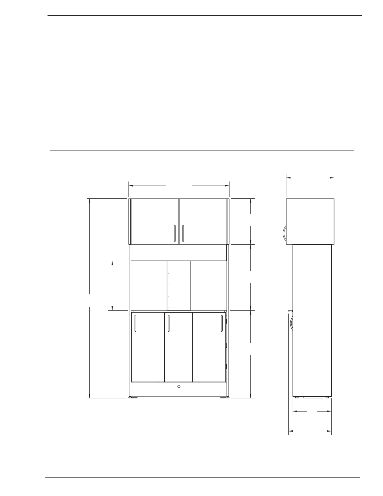
Model Designation: Pelton Classic Twelve O’clock Cabinet
Power Supply: CF—120V
Protection against harmful ingress penetration of water:
ordinary equipment
Mode of operation: CF—Continuous
~50Hz, 12A Service
CAUTION: Only authorized service technicians should attempt to service
this equipment. Use of other than authorized technicians will void the
warranty.
Product Identification
This cabinet can be identified by its product label, located underneath the
midsection front panel. This label states the unit model and serial number,
electrical specifications and safety classification.
Note the label shown below:sample
Obtaining Technical Literature
The manufacturer will make available on request circuit diagrams, component
parts lists, descriptions, calibration instructions or other information that will
assist technical personnel to repair and replace serviceable items.
Incompatible Units or Accessories
To guarantee the operational safety and function of this device, the use of
unapproved unit or accessories is not advised. Doing so could result in potential
hazard.
Interference with Electromedical Devices
To guarantee the operational safety of electromedical devices, it is
recommended that the operation of mobile radio telephones in the medical
practice or hospital is prohibited.
Strong EMI sources such as electro surgery units may affect performance.
If performance problems occur, move the unit to another electrical circuit or
physical location.
Equipment Disposal
Contact your local authorized dealer for proper disposal of the device to ensure
compliance with your local environmental regulations.
Thank you for purchasing your new cabinet.
Maintenance Instructions
It is engineered to provide
many years of reliable performance. However, a certain amount of care is
required. Conscientious adherence to the will
ensure that your unit will function to your satisfaction for many years to come.
Therefore, we have provided you with a set of technical literature, which may be
kept for quick and easy reference.
In order to protect your rights under the warranty, the purchaser must register
the unit by filling in the warranty information provided.
Safety Notes
This cabinet is not used in rooms where an explosion hazard exists.
The pre-installation of the facility must be performed in accordance with the requirements outlined in our “Pre-installation” instructions.
As the manufacturer of cabinetry, we can only assume responsibility from the safety related performance of the cabinet, if maintenance and repair are
carried out by the manufacturer, or by agencies authorized by Pelton & Crane for this purpose, and if needed components affecting the safety of the
appliance are replaced exclusively by original spare-parts.
We suggest that you request a certificate stating the type and extent of the work performed, from those performing such work, if necessary stating any
alterations of the rated parameters or operating ranges, as well as date, name of organization and signature.
This type of appliance is classified to UL 60601-1, EN 60601-1, certified to CSA C22.2 No. 601.1-M90. Due to legal regulations, alterations of the ,
which could impair the safety of the operator, patient, or third parties, are not lawful! For reasons of product safety, only original
In order to prevent injury to persons and damage to the equipment, you must also read the warning and safety notes given in this User’s Manual. These are
emphasized with WARNING, CAUTION and NOTE.
cabinet
Pelton & Crane accessories
approved for this product, or accessories by third parties, which have been approved by Pelton & Crane, may be used. Using non-approved accessories is
at the risk of the user.
34488
059334 REV 0, 03/11
Listed to: UL 60601-1
OPERATORY CABINET
CF
IEC Type B, Class 1
Listed to: CAN/CSA C22.2 NO. 601.1-M90
(115VAC, 12A, 60Hz)
MN
SN
MO
YR

4
CF36 Overview
A-C, upper module, storage
B, counter workspace
D, accessory panel
E, central column, power chase
K & M, lower module, storage
L, unit mount area
A
E
B
K
C
D
M
L

5
CF36 Cabinet Dimensions
The CF cabinet provides a work surface, storage, and can be installed with or without a Pelton & Crane delivery
system. The CF36 cabinet also provides a work surface and outlets. It is designed with the Dentist and staff in
mind to provide a robust working enviroment for the daily activities of performing dentistry. This product is intend-
ed for use by dental professionals.
CF36 Overview
72-1/2"
24"
31-1/2"
14"
16-1/2"
16-7/16"
17-7/16"
15-11/16"
17-15/16"

6
CF42 Overview
A-C, upper module, storage
B, CPU storage
D, accessory panel
E, central column, power chase
F, counter workspace
K & M, lower module, storage
L, unit mount area
A
E
D
K
C
B
F
M
L

7
CF42 Cabinet Dimensions
The CF cabinet provides a work surface, storage, and can be installed with or without a Pelton & Crane delivery
system. The CF42 cabinet also provides a work surface and outlets. It is designed with the Dentist and staff in
mind to provide a robust working enviroment for the daily activities of performing dentistry. This product is intend-
ed for use by dental professionals.
CF42 Overview
72-1/2"
24"
31-1/2"
14"
16-1/2"
17-7/16"
15-11/16"
17-15/16"
42-7/16"

8
Optional Computer Storage Overview
Optional Computer Storage Dimensions
A computer can be stored in the center storage area of the upper cabinet. Insert the computer’s cables through
the access holes in the bottom of the cabinet and route to the utility box. Place the CPU so the front is facing
the cabinet door.
Follow the computer system manufacturer’s installation procedure and plug the unit into the outlets in the utility
box.
Read computer system manufacturer’s recommended safety, use & care and installation instructions.
Follow the computer system manufacturer’s installation procedure.
21-1/2"
21-1/4"
42-7/16"
CPU storage
Upper
storage
Upper
storage

9
Preparing the Site
WARNING: Always lift cabinets by bottom edge, being careful to lift with your legs and not your back.
CAUTION: Make all required, air water and drain attachments from the utilities to the incoming stub up
connections before the delivery system installation occurs. Doing so prevents damage to the utility lines
from heat associated with some plumbing connection methods.
Turn main power OFF at the installation site.
WARNING: All Electrical wiring should be in accordance with local codes.
WARNING: To avoid risk of electrical shock this equipment must be connected to power mains with
protective earth.
NOTE: Use oor template to locate utilities in relation to the dental chair. Because of varying city plumbing and
electrical codes, the dealer should ensure that installation meets local requirements. Pelton & Crane
can not be responsible for an installation which does not meet local plumbing and electrical codes.
Select the location for cabinet that will meet the operator’s arm reach and storage requirements. Refer to
the dimensional drawings while considering the location of air, water and electrical connections.
SPECIFICATIONS (Floor Template depicted in Illustration)
Air & Water Shut-off Valves (If required for delivery) : 1/2” pipe N.P.T. (supplied by the contractor)
protruding 1” from oor or wall. Manual shut-off valve supplied by the dealer to be installed by the contractor.
Maximum height can not exceed 5” when valves are fully opened.
Electrical: 1/2” conduit and quad box or equal junction (supplied by the contractor). Wire box as per code with
top of the box no higher than 4 1/2” above nished oor.
Voltage:
120 Volts AC, 3 wire, 15 amp circuit.
Central Vacuum (if required): Plumbing should be specied and terminated in treatment column with 5/8” OD
tube perpendicular to oor, similar to drain connection.
WATER
AIR
N2O
O2
VACUUM
ELECTRICAL STUB UP
UTILTIES CHASE FOR RIGHT SIDE OF ROOM
UTILTIES CHASE FOR CHAIR
UTITLIES CHASE FOR LEFT SIDE OF ROOM
(OPTIONAL) (OPTIONAL)
(OPTIONAL)
OUTLINE
OF CABINET
BACK OF CABINET
5" 7" 11" 12-1/2" 27-1/4" 29-1/2" 32" 34-1/2" 37" 42"
4-3/4"
5-1/4"
6"
6-3/4"
8-1/4"
9"
14"
3-3/4"
Floor Template (CF42 Shown)

10
Preparing the Site (Cont’d)
1. Lay installation template over plumbing stub-ups and check the distance from the cabinet to the walls
according to operatory layout. (Floor template is depicted in illustration. Stub-up information in the tem-
plate illustration applies to all models.)
2. The shut-off valves for air and water must be installed above the nished surface as indicated in the
template: 5” max. when in an open position.
3. Install air and water shut-off valves.
NOTE: A 3/8” compression tting is recommended for the output connection on the cutoff valves.
4. Connect exible hoses from air and water regulator assemblies to the air and water shut-off valves.
NOTE: To ensure proper operation of the unit, ush air and water lines before connecting equipment.
Place oor mounting bracket over the templet
5. Mark the (4) moutnings (2 each side) according to the template. If mounting a 2800 delivery unit, also
mark the front and rear mounting holes according to the template.
NOTE: If ooring is carpeted, cut carpet away from the cabinet mounting point to gain stability to the
cabinet when secured to the oor.
6. Concrete Floor: Drill four 3/8” holes, 3” deep into oor.
Wood Floor: Drill four 1/4” holes, 2 3/4” deep into oor.
NOTE: The template illustration depicts the mounting points.
WALL ELEVATION
Allow 16" of 1/2" Flex Conduit to extend beyond
stub-up for electrical hook-ups.
ELEC.
NOTE: Will need to cut back cabinet wall when installing utilities from the wall.
Elec. Vacuum
Air Finished
Floor
Surface
2"
2"
4-1/2"
7"
9"
11"
13"
15"
(Optional)
BOX
N O
2O2
Water

11
Cabinet Installation
1. Remove the box and shrink wrap from around the cabinet.
2. Unclip the doors and/or drawers and place in a safe area.

12
3. Remove the shelves from the upper and lower cabinets .
Cabinet Installation cont’d.
4. Remove the (4) bolts, washers and nuts holding the cabinet section to the pallet.
Bolt
Nut Center brackets
used on 2800 only
Washer

13
7. Loosen the cabinet mounting brackets on
each side using the (4) 1/4” bolts installed
in the cabinet sides.
8. To level the cabinet, place a level on the
top of the countertop and adjust the (4)
leveling feet so that the cabinet is
completely level in all directions. Re-tighten
the (4) 1/4” bolts on the cabinet mounting
brackets on each side and re-check level-
ing.
5. Using the oor template provided, drill for
concrete (4) 3/8” x 3” deep holes, for wood
drill (4) 1/4” x 2-3/4” deep holes. For con-
crete insert (4) 3/8” x 2-3/4” anchor bolt,
washer, lock washer and nut, for wood in-
sert (4) 3/8 x 3-1/2” lag screw, lock washer,
and washer.
Note: On cabinets using a 2800 delivery
system, (4) additional holes will need to
be drilled and additional hardware used
to secure the cabinet to the oor.
6. Remove the cabinet mount assembly from
the pallet and place over the area marked
for the installation. Bolt the cabinet to oor
through the cabinet mounting brackets.
Note: Ensure that cabinet mounting
brackets are permanently and securely
fastened to the oor.
Cabinet Installation cont’d.
Floor
Template
Center brackets
used on 2800 only
Cabinet
Mounting
Bracket
Cabinet
Mounting
Bracket
Center brackets
used on 2800 only
Level
Leveling
Feet
Cabinet
Mounting
Bracket
Leveling
Feet
Cabinet
Mounting
Bracket

14
9. Connect utilities in accordance with local
codes.
10. Re-install shelves and/or drawers and
doors removed previously, taking care to
place them in their original positions.
Cabinet Installation cont’d.

15
Door & Drawer Adjustment
Cam wing mounting plate
One piece wing plate
Range (5/32")
Range (5/32")
Rotate front screw to increase or
decrease door position.
Range (3/32")
Rotate spiral -tech cam
screw to adjust door position.
Range (3/16")
WARNING over-adjusting hinges can cause damage
Note:
Upper & lower plates
must be moved
together for each door
Note:
Upper & lower plates
must be moved
together for each door
Drawer front adjustment - Standard
Vertical Adjustment
4.
5. Turn clockwise to raise -
counter clockwise to lower,
re-tighten Attachment Screw.
Loosen Attachment Screw
6. Tilt adjustment
(for large drawers only)
Horizontal Adjustment
1. Loosen Mounting Screws
2. Adjust Front
3. Tighten Screws
1
1.
2/3.
4.
5.
6.
Vertical Adjustment
4. Loosen the attachment
screw. Adjust drawer
front up/down then
tighten screw.
Horizontal Adjustment
1. Loosen Mounting Screws
2. Adjust Front
3. Tighten Screws
1.
4.
2/3.

16
Clock Instructions
To Set Calendar/Clock
The CLOCK button is used to alternate between 12 hour (AM / PM) and 24 hour (International / Military time)
clock modes. When you insert the battery, the clock will automatically be in the 12 hour clock mode. If you would
like the clock to be in the 24 hour clock mode press CLOCK before setting the clock. The letters AM or PM will
appear for 12 hour clock only.
To set the calendar/clock, rst press the SET button to adjust the settings. When SET is pressed, the ashing
gures will display in the following sequence: year, month, date, hours, minutes, seconds. Press the or but-
tons to change the calendar or the clock. The button will decrease the numbers and the button will increase
the numbers.
NOTE: The day of the week will automatically change when you change the date.
To Use Stopwatch
(Times up to 23 hours, 59 minutes, 59 seconds)
Press the STOP WATCH button to enter the Count-up/Stopwatch mode. Press the START/STOP button to begin
counting up in seconds. Press START/STOP again to stop time. Press again to restart. After you stop the time,
press the and buttons at the same time to clear the time and reset to 00:00.
Your timer can time up to four activities at once, if desired. The maximum time for each being 23 hours, 59 min-
utes, 59 seconds.
To Use The Basic Timer
First press the TIMER button to enter the timer mode. The number “1” will be displayed in the upper right hand
corner of the timer. Then press SET and using the and/or buttons, set the desired timing period (hours,
minutes and seconds). Next press START/STOP to begin timing. Any time during the timing period the timer can
be stopped by pressing START/STOP. Press START/STOP again to restart. Once time elapses, alarm will sound
for 60 seconds. Timer will count up to show how much time has elapsed since the timer sounded. Press START/
STOP to stop the tone and count-up time and reset to 00:00.
To Use Memory Timers 2, 3, and 4
First press TIMER to enter the timer mode. Then press the MEMORY 2-3-4 button. Each time you press
MEMORY 2-3-4, a different number will appear in the upper right hand corner of the timer. That number indicates
which timer is being used. Press SET and using the and/or buttons set the desired timing period for each
timer.
When you set timers 2, 3, and 4, the times will automatically be stored. To reset any of the stored times, press
the and at the same time and this will erase the time in the memory.
Memory Recall
To recall a stored time after the time has expired, rst make sure you are in the timer mode, then press MEMORY
2-3-4 until the correct timer is displayed.
NOTE: Timer 1 is a basic timer and does not include the memory recall feature.

17
Electrical Diagram
INPUT POWER
CABLE
BLK
WHT
WHT
GRN
BLK
BLK
GRN
( WIRE NUT)
WHT WHT
G/Y
G/Y

18
Verify the following after installation or servicing of the cabinet:
All manuals are present.
All labels are present and legible.
No mechanical damage on new installations.
The cabinet is connected to the correct power source.
There are no water or air leaks.
All the cabinet adjustments have been made according to the users manual.
Ensure control panel functions properly.
Installation and Servicing Checklist

19
NOTES

Pelton & Crane
11727 Fruehauf Drive
Charlotte, NC 28273
USA
Order No. 059351
Rev. 0, 4/11
Printed in USA
We reserve the right to make any alterations which may be due to any technical improvements.
© 2011, Pelton & Crane
This manual suits for next models
1
Table of contents
Other Pelton & Crane Indoor Furnishing manuals
Popular Indoor Furnishing manuals by other brands

Furniture of America
Furniture of America Lennart CM7386CK Assembly instructions

Dorel Living
Dorel Living DL058-SF Instruction booklet

Eaton
Eaton LMS installation manual

ERBA
ERBA Tall cabinet 2 doors instruction manual

Multay
Multay Perpignan PR001 Assembly instruction

Homelegance
Homelegance B2013BCDC-1 Assembly instruction

Continental Refrigerator
Continental Refrigerator PC Series instructions

MH LONDON
MH LONDON MH-BS-928 Assembly instructions

Otto
Otto WF297721AAAW Assembly instruction

IKEA
IKEA GODMORGON WASH-STAND W/2 DRWS instructions

Furniture of America
Furniture of America CM3424T Assembly instructions

JWA
JWA GATES 75251 Assembly instruction