2. Layout the closet sections
▪Your closet design will need a small gap on each end, typically between 1” and 2”. This
is to ensure that the closet system can be assembled without the constraints of imperfect
wall conditions.
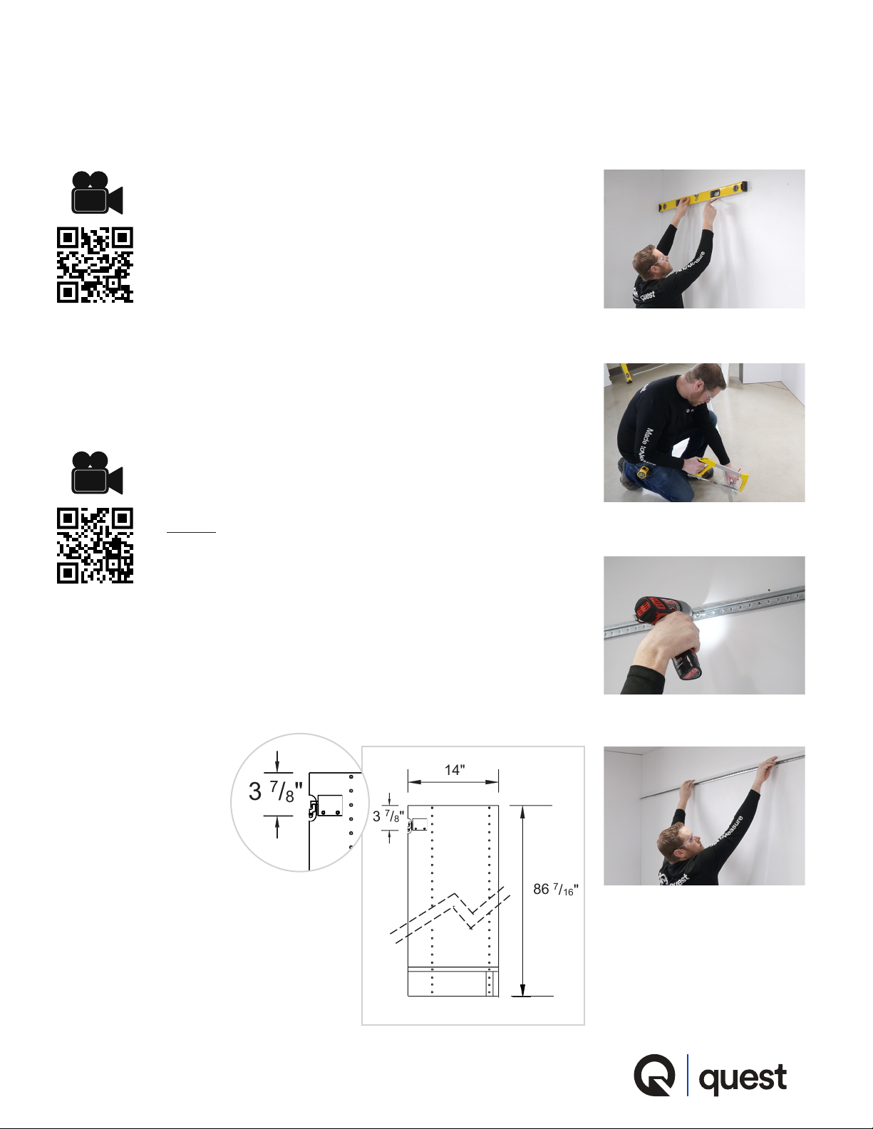
▪Determine overall wall dimension, then subtract the
designed closet overall width. Leave about half of that
balance on the far right of the closet, and the other half
on the far left of the closet. Keep in mind that the overall
designed width of the closet may increase slightly as you
assemble the closet.
▪Layout the vertical partition locations. (Figure 5)
3. Organize the closet components
▪According to your closet design, locate the appropriate closet components near their
installation location, beginning with the vertical partitions.
▪Next, organize the xed shelves near the vertical partition locations.
▪No need to organize the adjustable shelves, clothes rods, drawers, or any other
accessory at this time.
Figure 5
Figure 6
Figure 8
CLOZX
Closet Installation
Figure 7
4. Install the vertical partitions
▪Begin from the far right or far left of each wall. If you have a
wall with an open-ended system run, begin against the wall.
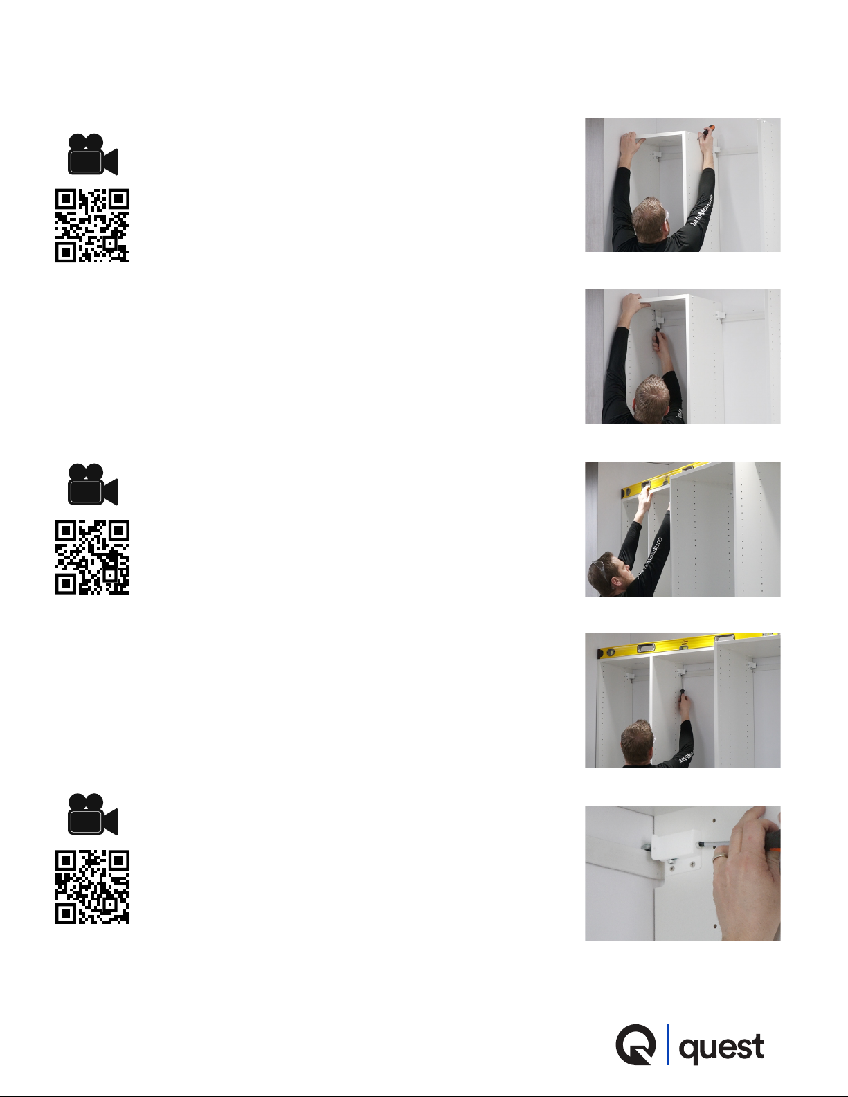
▪Each vertical partition will require a panel hanger. (Figure 6)
The panel hangers are attached near the top of the partition,
and fastened with 2 – 5mm Euro-Screws. NOTE: There are
right and left-handed panel hangers, use according to the
requirements on your design.
▪Please reference the individual module instructions for
further information.
▪Hang the partitions.
▪Do not adjust the panel hanger at this time, unless you must
due to extreme wall variations.
▪There are 2 different connector dowels used in assembly (Figure 7):
◦The screw-in dowel is used when a common shelf is not
required, or at the rst or last partition.
◦The push-in dowel is used when a common shelf is
present; where there is a shelf in the same location on
each side of the vertical partition (such as the top).
▪You will want to pre-assemble any connectors required on
the partition. This will be determined by the module type. (Figure 8)
2
4
screw-in dowel
push-in dowel
VIDEO 2
VIDEO 4