4042281 R03
GENERAL INFORMATION
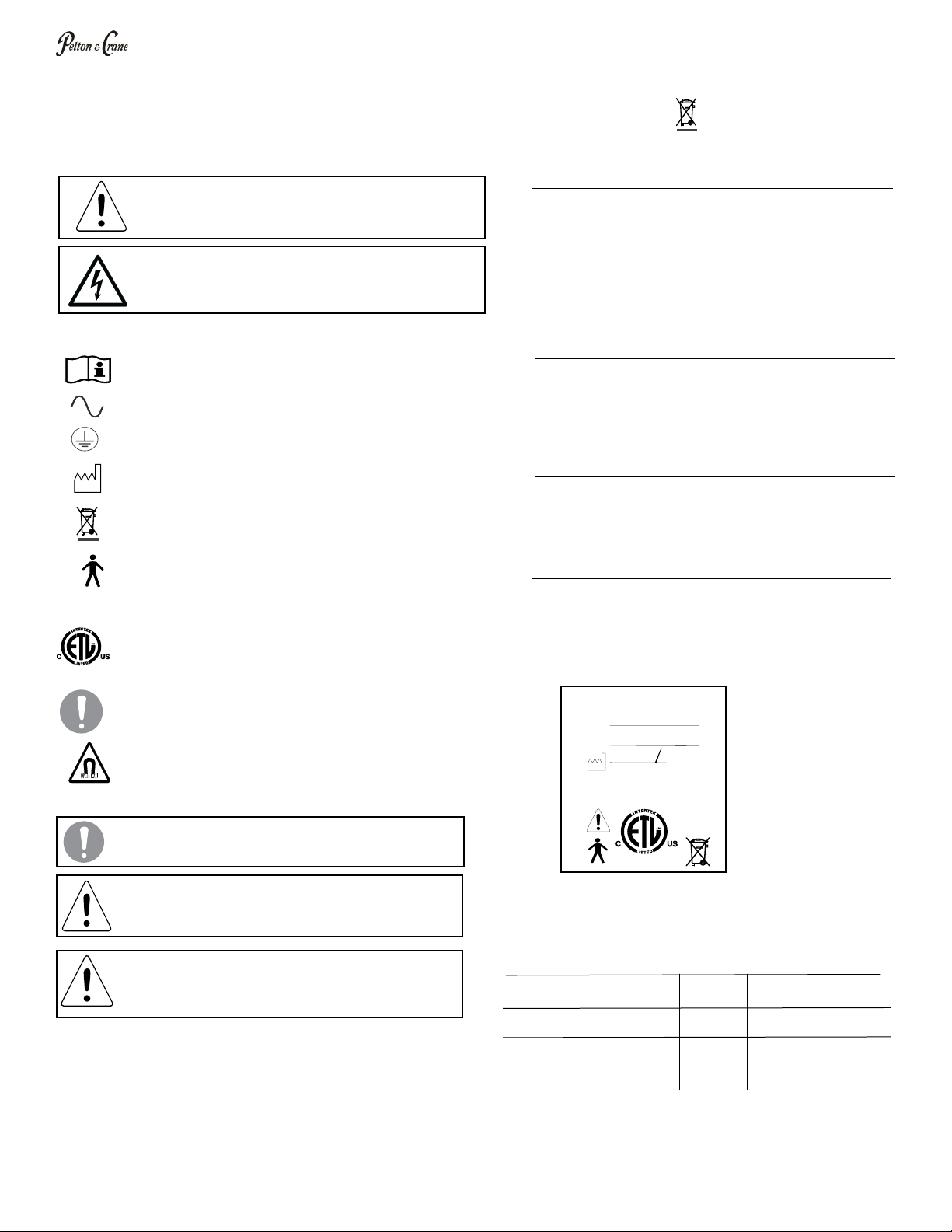
Denition of Symbols
The following symbols may be used throughout
this manual:
The following symbols may be located throughout the product:
WARNING: Only authorized service technicians should
attempt to service this equipment. Use of other than
authorized technicians will void the warranty.
WARNING: This product must be disinfected before
use.
WARNING: Failure to carefully follow the described
procedure may result in damage to the equipment and/
or injury to the patient/operator.
Risk of electrical shock present. Make sure power is
disconnected before attempting this procedure.
Product Disposal
Contact your local authorized dealer for proper disposal of the
device to ensure compliance with your local environmental
regulations.
Interference with Electromedical Devices
To guarantee the operational safety of electromedical
devices, it is recommended that the operation of mobile radio
telephones in the medical practice or hospital be prohibited.
Strong EMI sources such as electro surgery units or x-ray
units may effect performance. If performance problems
occur, move the light to another electrical circuit or physical
location.
Incompatible Units or Accessories
For reasons of product safety, only original Pelton & Crane
accessories approved for this product, or accessories from
third parties which have been released by Pelton & Crane
may be used. It is the user’s risk when using non-released
accessories are used.
Obtaining Technical Literature
The manufacturer will make available on request circuit
diagrams, component parts lists, descriptions, calibration
instructions or other information that will assist technical
personnel to repair and replace serviceable items.
Product Identication
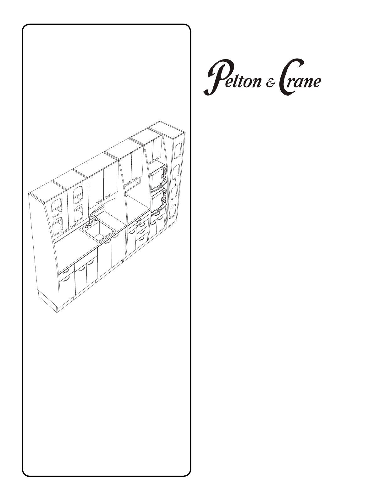
This dental cabinet can be identied by its product label,
located on product. This label states the model and serial
number, electrical specications, manufacture date and
safety classication. Note the SAMPLE label shown
below.
Technical Description
Model Designation: Solaris Sterilization Center
Power Supply: 120V~60Hz, 15A Service
Circuit Description Voltage Current Freq.
Control Box/Lighting Circuit 120V 3A per circuit 60 Hz
Receptacle Circuits (120V) 120V 12A per circuit 60 Hz
Receptacle Circuits (230V) 230V 12A per circuit 60 Hz
Optional for Sterilizer
Receptacles
Protection against harmful ingress penetration of water:
ordinary equipment
See operating instructions.
Protective earth (Ground)
Manufacturing Date
Waste Electrical and Electronic Equipment.
Type B Applied part.
Indicates conformity to General Requirements for
Safety is certied by Intertek Testing Services.
General mandatory action required, important to fol-
low instruction. Not a caution.
Warning, strong magnetic eld.
(AC) Alternating current.
34488
051038 REV 3, 01/09
STERILIZATION CENTER
SSC
MN
SN
MO
YR
Conforms
to: UL STD 962
Certified to:
CAN/CSA STD C22.2 NO. 203.1-94
WARNING: Maximum load for slide-ouit shelves
on the Strerilization Tower is 135 lbs.