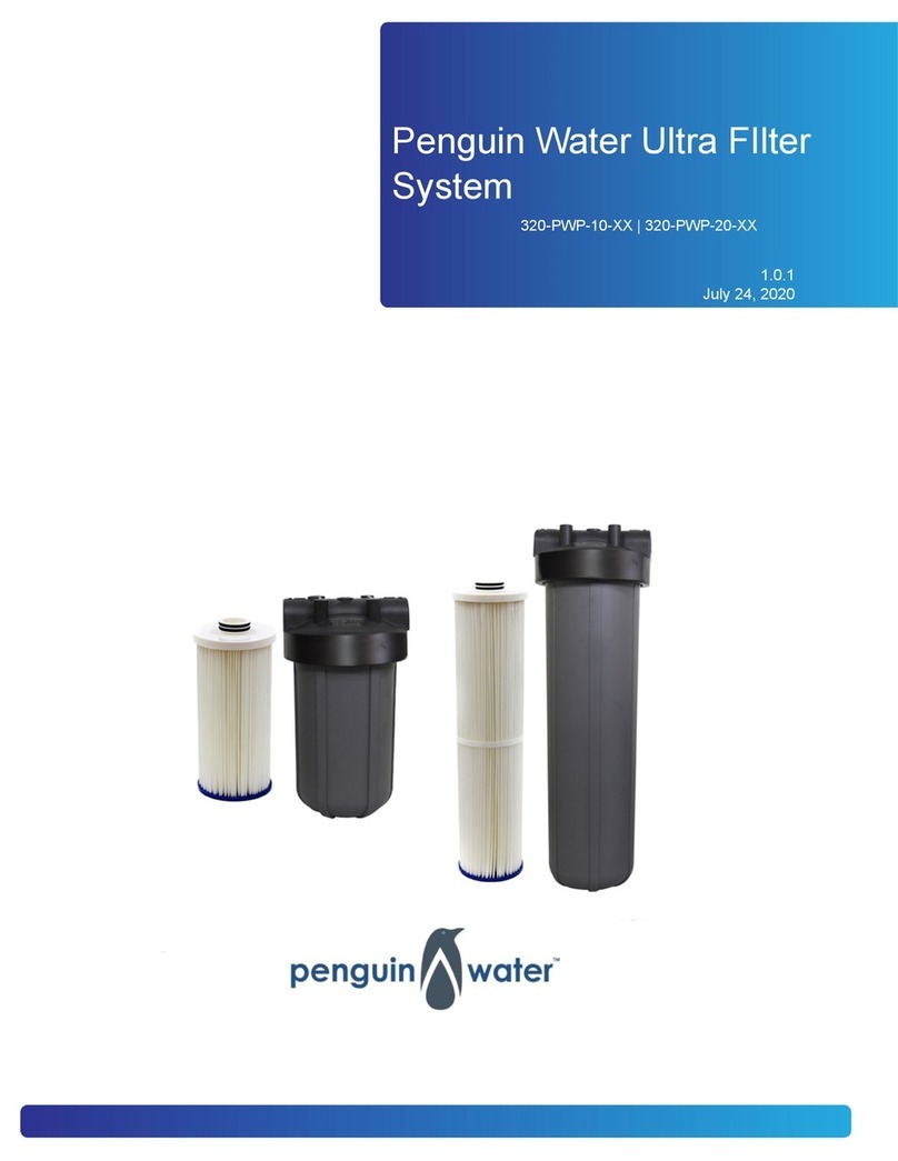
Penguin Water 200-PWRO Series User manual

Penguin Water Reverse
Osmosis System
200-PWRO-XXXX | 200-PWRO-XXXX-P | 200-PWARO-XXXX | 200-
PWARO-XXXX-P

Table of Contents
Parts Check List ........................................................................................................ 3
Parts Overview .......................................................................................................... 5
Tools Needed ............................................................................................................ 6
Quick Connect Fittings .............................................................................................. 7
How To Make a Connection ............................................................................... 7
Disconnecting .................................................................................................... 8
Installation Location .................................................................................................. 9
Installation ............................................................................................................... 10
Faucet Installation ............................................................................................ 10
Feed Water Angle Stop Valve and Tubing Installation ..................................... 12
Drain Saddle Installation .................................................................................. 14
Tank Installation ............................................................................................... 15
Initial Tubing Connections ................................................................................ 16
RO Unit Installation .......................................................................................... 16
Final Tubing Connections ................................................................................ 16
System Start Up ...................................................................................................... 19
Prior to Start Up ............................................................................................... 19
Flushing System and Checking Operation ....................................................... 19
Air Purging ....................................................................................................... 19
Maintenance ............................................................................................................ 21
Sanitizing Filter Change Instructions ....................................................................... 22
Flushing System and Checking Operation ....................................................... 23
Air Purging ....................................................................................................... 23
Why the Regular Use of Sani-System is Important .......................................... 24
Standard Flow Diagram .......................................................................................... 25
Permeate Pump Flow Diagram ............................................................................... 26
6 Stage RO Flow Diagram ...................................................................................... 27
6 Stage RO Permeate Pump Flow Diagram ........................................................... 28
Warranty .................................................................................................................. 29
2

Parts Check List
• RO Module
• Tubing Bundle
• Filter Wrench
• 1/4" Drain Saddle
•Tank Valve
•Angle Stop Feed Valve
•Tank and Side Mount Tank Stand
• Faucet Connector
3

• Pre and Post Filters + Membrane (Pre-Installed)
• Alkaline Filter (Included with 6 Stage System)
4

Parts Overview
•Pre-Filter (Sediment Filter) - Removes larger particles such as sand, silt, rust and
scale.
•Pre-Filter (Activated Carbon Filters) - Removes chlorine and chloramine in the feed
water to protect the reverse osmosis membrane.
•Reverse Osmosis Membrane - Reduces dissolved minerals, metals and salts. During
the process, harmful compounds are separated by the membrane and the reject water
goes to waste (drain).
•Post-Filter - Provides a final "polish" and removes foul tastes and odors to provide
great tasting drinking water.
•RO Module - Housings hold the pre-filters and membrane while the bracket is provided
to mount the system, typically below a sink.
•Storage Tank - Holds filtered water that is ready for use.
•Automatic Shut-Off Valve (ASO) - Senses when the storage tank is full and closes
the water supply to conserve water. (Not used in a permeate pump system)
•Permeate Pump - Used to pressurize the tank and distribution system. This pump is
operated by the drain water. The permeate pump will dramatically increase the faucet
pressure. (A permeate pump system will not have an ASO valve.)
•Feed Water Angle Stop Valve - Connected to the cold water line to supply water to
the RO system.
•1/4" Waste Water Saddle Valve - Connected to the drain to remove reject water from
the RO system. (If using an air gap faucet, this will need to be a 3/8" saddle valve.)
•Tubing - Supplies feed and reject water.
•Fittings - Used for necessary hose connections.
5

Tools Needed
The following tools may be necessary depending on each particular installation:
• 3/8 Drill and 1/4" drill bit
• Faucet Drill Bit (For standard faucets, use a 7/16" drill bit. For Air Gap faucets, use a
7/8" minimum, 1 1/8" maximum drill bit.
• Phillips head and flat blade screwdrivers
• Adjustable wrench
• Teflon tape
• Plastic Tube Cutter
6

Quick Connect Fittings
Many RO systems utilize quick connect fittings. These user-friendly fittings provide supe-
rior performance and are provided with this system. Proper use of these push-in fittings is
shown below. Along with these fittings, all tubing selected must be of high quality and
must be cut with a plastic tube cutter or sharp razor with a clean, square cut.
How To Make a Connection
1. Cut the Tube Square - It is essential that the outside diameter be free from score
marks and that burrs and sharp edges be removed before inserting the tube into the
fitting. For soft, thin walled tubing, we recommend the use of tube inserts.
2. Insert Tube - The fittings will grip before a seal is formed. Ensure the tubing is push-
ed fully into the tube stop.
3. Push up to the Tube Stop - Push the tubing into the fitting, up to the tube stop. The
collet (gripper) has stainless steel teeth which hold the tubing firmly in position while
the O-ring provides a permanent, leak proof seal.
4. Pull to Check Secure - Pull on the tubing to check that it is secure. It is a good prac-
tice to test the system prior to leaving the site and/or before use.
7

Disconnecting
Push in Collet and Remove Tubing - To disconnect, ensure the system is depressur-
ized before removing the tube, Push in the collet squarely against the face of the fitting.
With the collet held in this position, the tube can be removed. The fitting can be re-used.
Should a leak occur at a fitting, the cause is generally defective tubing. To fix a leak, re-
lieve pressure, release tubing, cut off at least 1/4" from the end (square cut), reattach the
tubing, and confirm the connection is leak free. Each time a new connection is made, it is
advisable to cut off 1/4" from the end of the tubing using these fittings.
8

Installation Location
The RO system may be installed under a sink, in a basement, or other location depend-
ing on available space. Do not install unit where temperatures fall below freezing. Other-
wise, damage will occur. Connection to an ice maker should also be considered for opti-
mum performance.
•Storage Tank - May be placed where it is convenient within ten (10) feet of the RO
module. Under the sink or in a nearby cabinet are excellent choices. Full tanks may
weigh more than thirty pounds so a sturdy shelf is required.
•RO Module - May be mounted on either side of the sink, in a cabinet, or a heated
basement with nearby access to a potable, cold water line and a sanitary drain.
•Feed Water Connection - Accomplished with an angle stop feed water valve. This
valve will be installed in the cold water line between the sink cold water shutoff valve
and the sink faucet tubing. Connect to a potable, cold water supply line only
NOTE: Softened water is preferred since it will extend the life of your RO mem-
brane.
•Drain Connection - Accomplished using a waste water saddle valve which is designed
to fit around a standard 1-1/2" OD drain pipe. The drain saddle valve should always be
installed above (before) the trap and on the vertical or horizontal tailpiece. Do not In-
stall the drain saddle valve near a garbage disposal; otherwise, plugging of the waste
water line may occur. If discharging into a utility sink or standpipe, an air gap may be
needed. (Air gaps must be 1” or greater above the floor or pipe rim).
NOTE: Plumbing codes may require the use of air gaps. Check with your local
municipality.
Do not connect the RO system drain line to the dishwasher drain line. Back pressure in
the line may cause the air gap to over flow.
9

Installation
Faucet Installation
1. If the sink has a sprayer, it may be disconnected for faucet installation. A pipe cap or
plug will be necessary to seal the sprayer connection. To make the faucet mounting
hole (if sprayer or second hole is not used), check below the surface to ensure the
drill does not interfere with anything. Drill a 7/16" hole for non air gap faucets. If an
air gap faucet is being used, drill a hole that is 7/8" minimum 1 1/8" maximum. Be
sure to use a drill bit compatible with your surface. Clean up any sharp edges or
burrs once the hole is drilled. The faucet should be positioned so it empties into the
sink and the spout swivels freely for convenience. If the sink has a hole that can ac-
commodate the RO faucet, no drilling is required. Proceed with mounting the faucet.
Figure 1. Faucet Installation Without Air Gap
10

2. Install the faucet as shown in Fig 1. Assistance may be needed to hold the faucet in
place while the nut is tightened.
3. Once the faucet is secure, install the 7/16" UNS x 3/8" QC faucet connector on the
threaded nipple. This fitting does not require sealant as it seals at the beveled sur-
face. Tighten the fitting hand tight then use an adjustable wrench to tighten an addi-
tional 1/2 turn.
4. Now push the blue tube into the faucet connector. Leave the other end of the blue
tube unconnected for now. It will be connected later in the installation.
11

If an air gap faucet is being used, follow this next set of steps.
1. Connect the 1/4" drain line from the RO module to the smaller brass barb on the bot-
tom of the faucet. Be sure the tube is completely pushed on the barb or a leak could
occur. If using a permeate pump, this connection will be made later in the installation.
2. Now push a piece of 3/8" black tubing onto the larger brass barb on the bottom of the
faucet. Be sure the tube is completely pushed on the barb or a leak could occur.
Leave the other end of the black tube unconnected for now. It will be connected later
in the installation.
Feed Water Angle Stop Valve and Tubing Installation
1. To install the angle stop valve, turn off the cold water supply valve for the sink faucet.
Open the sink faucet cold water and relieve the pressure.
12

2. Remove the sink faucet "whip hose" or tubing from the shutoff valve. There will be
residual water spilled when this tube is removed. Be sure to have a towel to dry the
water that is spilled. Now install the angle stop valve on the sink faucet shutoff valve
and tighten it. Use two wrenches to hold the valve while tightening. Don't worry about
the angle stop valve position because it will swivel and can be positioned later.
3. Install the whip hose or tubing on the angle stop valve and tighten.
13

4. Be sure the blue handle on the angle stop valve is in the closed position (as pic-
tured). Now open the sink shutoff valve and check the angle stop connections for
leaks. If there are leaks, repair them now. If there are no leaks, connect the orange
tubing to the angle stop valve. Leave the other end of this tubing unconnected for
now. It will be connected later in the installation.
Drain Saddle Installation
Prior to Drain saddle installation, it is important to inspect the condition of drain pipes to
make sure they are not thin and frail. Drain saddle valves are designed to be installed on
standard 1-1/2" OD drain pipe. Install the drain saddle valve above the trap (between the
sink and trap) and on the vertical or horizontal tailpiece. Never install a drain saddle valve
close to the outlet of a garbage disposal or plugging of the RO drain line may result.
1. Position the port side of the drain saddle valve at the selected location and mark for
the opening. Never position the opening at the bottom of the pipe. A side or top posi-
tion is recommended. Install the rubber gasket on this half of the drain saddle. Be
sure the gasket hole is lined up with the port hole.
2. Drill a 1/4" hole (3/8" hole if using an air gap faucet) at the spot previously marked.
Take care not to drill through both sides of the pipe.
14

3. Position both halves of the drain saddle on the drain pipe so the quick connect open-
ing lines up with the the previously drilled hole. A screwdriver may be used to keep
the holes oriented during the tightening process.
4. Secure the drain saddle clamp on the drain pipe with the provided nuts and bolts.
(Do not over tighten. Make sure there is equal space between saddle halves on each
side.)
5. Install the black drain line to the port on the drain saddle. If using an air gap faucet,
connect the 3/8" black line from the larger brass barb to the drain saddle.
Tank Installation
1. Apply Teflon tape to the tank outlet threads. 3 - 4 wraps will be sufficient.
2. Install the tank valve by turning it clockwise. Tightening it hand tight is usually ade-
quate but additional tightening may be required.
3. Once the valve is installed, connect the green 3/8" tubing to the tank valve. Leave
the other end of the tubing loose. It will be connected later in the installation. NOTE:
Tanks are pre-pressurized at 7 psi. Prior to installation, check and add or re-
lease as required. Tanks should always maintain 7 psi
15

Initial Tubing Connections
It may be desirable to leave the excess tubing when making the final connects. This will
allow space to pull the unit out of the cabinet for filter changes without disconnecting all
the tubing. If you want to secure the system and cut the tubing to fit, that is fine, but this
may require that the system be removed for filter changes or the filters will have to be
changed with the system in the cabinet, which can be difficult.
RO Unit Installation
The RO Unit is normally mounted to the sink cabinet sidewall, depending on where the
supply tank is to be located. Generally, the unit is installed at the front of the cabinet and
the tank at the rear.
To mount the unit, elevate it at least 2" off the floor, level it, and mark the location of the
mounting holes needed. Drill holes for mounting screws then proceed to install the
mounting screws. Allow the mounting bracket slots to slip over them.
NOTE: If the cabinet sidewalls are not solid, the unit may sit on the floor with
screws installed to keep it against the cabinet in a vertical position. The system
does not have to be secured to the wall but it is a good practice. If the system is
not mounted to the cabinet wall and the tubing is not cut short, the module can be
removed from the cabinet during filter changes.
Final Tubing Connections
With all components in place, complete final tubing connections using these guidelines
• Tubing should follow the contour of the cabinets.
• Cut tubing to desired length using square cuts or a proper cutting device.
• Ensure there are no sharp bends
Proceed with final tubing connections using the provided flow diagrams and the following
procedures.
1. Connect the blue tubing from the faucet to the RO units post carbon filter outlet el-
bow fitting.
16

2. Be sure the storage tank shutoff valve is in the closed position. Use the supplied sy-
ringe and add 5ml of the supplied sanitizing solution to the green tank tubing attach-
ed to the storage tank. Connect the open end of the green tubing from the tank to the
RO units post carbon filter inlet tee fitting. Leave the tank valve closed.
3. Connect the orange tubing from the angle stop supply valve to the RO unit at the
sediment filter inlet fitting. When facing the unit, this is the far right sump.
Permeate Pump Installation - If the system is equipped with a permeate pump, clip
the pump to the membrane housing using the supplied mounting bracket and make
the connections to the pump using the label on the pump and the flow diagrams pro-
vided. The BRINE OUT connection will be made in the following step.
17

4. Connect the 1/4" black tubing from the RO unit to the drain saddle. If the system is
equipped with a permeate pump, run a length of tubing from the "Brine Out" port on
the permeate pump to the drain saddle connection. If an air gap faucet is being used
and the system is equipped with a permeate pump, run a length of tubing from the
"Brine Out" port on the permeate pump to the smaller brass port on the faucet.
18

System Start Up
Prior to Start Up
1. Check all connections and ensure they are secure.
2. Turn on the feed water valve and check for leaks. (Turn off and correct leaks if any
occur)
3. Close the valve on the storage tank (The tank should be closed from the Final Tubing
Connections) and open the faucet until a steady stream of water flows. Water will be
flowing to the drain as well.
4. Once there is a steady stream of water coming from the faucet (about 1/8" in diame-
ter), close the faucet and wait five minutes to see if any leaks result on the system.
The initial water from the system may be discolored. This is normal.
NOTE: It is very important that there is a steady stream (not drips) of water
coming from the faucet before it is closed. If not, there could be air trapped in
the system and it will not fill the tank properly. This can waste a larger volume
of water.
5. If there are no leaks, open the storage tank valve and allow the system to fill. Most
systems will be full within 2 hours. The system is full when the water to the drain
stops. Check for leaks with the system full and repair them accordingly.
NOTE: When the system is first turned on, water may intermittently "spurt"
from the air gap opening on the side of air gap faucets. This is common and
should correct itself after the air is purged from the system.
Flushing System and Checking Operation
To make sure the RO system is operating correctly, follow these simple procedures:
1. Open the faucet handle and allow the tank to completely drain. (Water will be discol-
ored and will have suds from the sanitizing solution)
2. Close faucet and re-fill the system.
3. Allow system to process water for approximately 2-3 hours. The tank will be practi-
cally full at this point.
4. Open the faucet again and allow the tank to empty for a second time. Do not use this
water.
5. Wait another 2-3 hours to allow tank to re-fill.
Air Purging
If the tank does not fill, the tank tubing may have air in it. Typically the standard startup
procedure will be sufficient but in some cases, due to the water temperature and pres-
sure, additional air bleeding must be performed. The following procedure will help bleed
air from the system.
19

1. Close the tank valve and the feed water valve and open the faucet to relieve the
pressure on the system.
2. Remove the tank tubing from the tank valve and hold it over a bucket or pan.
3. Open the feed water valve and the faucet.
4. Allow the system to run until there is a stream of water coming from the tank tubing.
5. Once there is a steady stream coming from the tank tubing, push it back into the tank
valve. Be sure to push it in the tank valve completely or a leak could occur.
6. Turn the tank valve on and allow water to run until there is a steady stream coming
from the faucet. Then shut the faucet and allow the tank to fill.
NOTE: If no objectionable tastes are noticed after a second tank draining, RO pro-
cessed water is ready for use. Otherwise, drain the tank and re-fill for a third time.
20
This manual suits for next models
3
Table of contents
Other Penguin Water Water Filtration System manuals
Popular Water Filtration System manuals by other brands

Sharp
Sharp FZ-560CF Operation manual

Coway
Coway P-07QR Owner's instructions

Filtration Group
Filtration Group EWH 16 Translation of the original instructions

Boss Water Systems
Boss Water Systems 021-4PC Installation and service guide

Clear2O
Clear2O GRAVITY GRP200 use and care manual

Brita
Brita PURITY 1200 Clean Extra manual