Pensa Labs D.I.Wire Pro User manual

Version 19.4.16
1

Table Of Contents
INTRODUCTION
HARDWARE SETUP AND SAFETY
BENDING
SETTING UP WIREWARE
PATH MODE
SCRIPT MODE
MATERIAL PROFILE
MAINTAINANCE AND TROUBLESHOOTING
2

Introduction
SECTION 1
3

THE D.I.WIRE PRO
D.I.WIRE PRO AND ITS COMPONENTS
GETTING TO KNOW THE D.I.WIRE PRO
Introduction
01 INTRODUCTION
4

The D.I.Wire Pro
01 INTRODUCTION
The D.I.Wire Pro is our newest desktop
CNC wire bender offering the power,
speed, precision and modularity that
professionals need. Bend any wire
material between 0.027” (0.7mm) and
0.188” (4.8mm), bend strap, and add
a straightener and other accessories to
optimize production.
5

Use the D.I.Wire Pro only as instructed in this
manual. Make sure you read all the instructions
and safety precautions before using the machine.
Before Use:
The D.I.Wire PRO is to be used by qualified
personnel only.
This manual contains valuable info about the
operation, care and service of your machine.
We recommend you keep it handy.
Note: The instructions in this manual are not meant
to cover every possible condition and situation
that may occur. Common sense and caution must be
practiced when setting-up, operating
and maintaining any equipment.
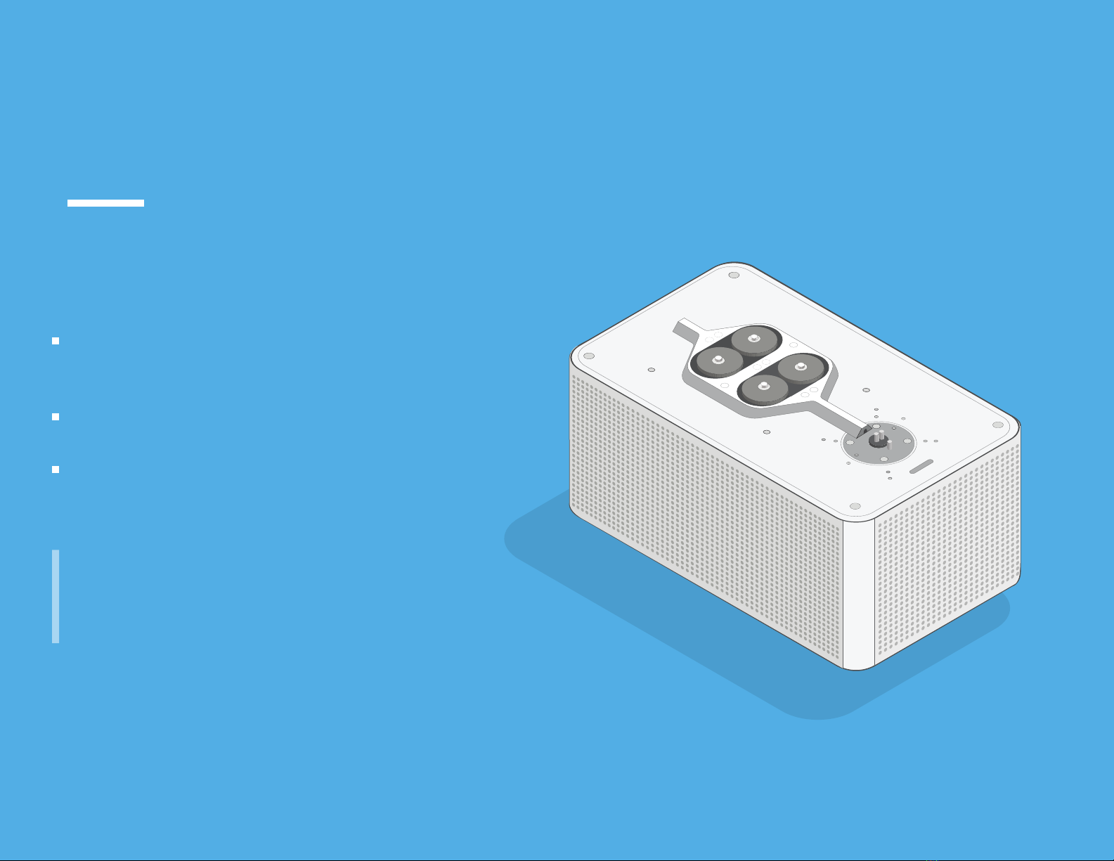
The D.I.Wire Pro
01 INTRODUCTION
6

AC Wall Adaptor
24 Volts 5A
Used for
all hardware
fasterners
D.I.Wire comes assembled with your specific
Bend Head, Bend Ring and Feed Wheels.
Keep tools and hardware somewhere safe!
BEND HEAD + BEND RING + FEED WHEELS
D.I.WIRE PRO
1/8 HEX KEY
3/32 HEX KEY
5/32 HEX KEY
RAMP
GUIDES
Guides are custom for
each material diameter.
45.01
CALIBRATION PLATE
Used for creating Material Profiles
and part inspection
USB allows D.I.Wire to
communicate with the computer
SMALL
TORQUE WRENCH
SOCKET
WRENCH
LARGE TORQUE WRENCH
CUTTERS For the Feed Wheels
For the Bend Head
D.I.Wire Pro and Its Components
01 INTRODUCTION
THE MACHINE TOOLS AND ACCESSORIES*
*Your set of tools may dier, depending on what you purchased. 7

RAMP Protects feed system
during bending
FEED WHEELS Feed material through
Bend Head
BEND PIN Bends material around
Bend Head.
BEND RING Moves Bend Pin. Custom
made with Bend Pin for
each material and matched
to Feed Wheels and Guides.
BEND HEAD Typically has two mandrels
to form wire.
ACCESSORY
MOUNTS
#10-32 tapped holes for
holding accessories, such as
a wedge
CUT OFF SLOT Hole for inserting cutters
Take a few minutes to get oriented to the D.I.Wire Pro.
TOP VIEW
WIRE GUIDES Hold material in place as it
is bent. Interchangeable to
accommodate specific
material diameters
DETAIL
Getting to know the
D.I. Wire Pro
01 INTRODUCTION
8

Hardware Setup And
Safety
SECTION 02
9

GETTING SET UP
D.I.WIRE ORIENTATION
SAFETY AND PROTECTION
DO’S AND DON’TS OF THE MACHINE
Hardware Setup And
Safety
02 SETUP AND SAFETY
10

Start by choosing a work area that is appropriate for your D.I.Wire.
CHOOSING A WORK AREA
1
Place the D.I.Wire away from any surface
that could obstruct the air flow and cause
overheating. Ideally, you’d place the machine
on a sturdy table or work bench by itself.
The D.I.Wire is a heavy machine. Make sure
you place it on a hard, flat, and sturdy surface
that can support the D.I.Wire’s weight and
remain flat. Particle boards, thin sheet metal,
or wire racks are not strong enough.
Make sure the work area is well illuminated,
and kept clean, free of excessive dust, debris
and liquids.
!!
Getting Set Up
02 SETUP AND SAFETY
11

SPATIAL ARRANGEMENT
The D.I.Wire requires sufficient work space for the following areas:
Back of the system for material loading; front of the system for part bending; and a dedicated area for the computer running WireWare
D.I. Wire
Orientation
02 SETUP AND SAFETY
MATERIAL LOADING AREA
BEND AREA
Keep clear for parts to move
freely during bending
Caution Area
12

Getting Set Up
02 SETUP AND SAFETY
THE D.I.WIRE PRO IS A HEAVY MACHINE AND
COULD CAUSE INJURY IF LIFTED INCORRECTLY.
To be safe, use assistance while lifting your
D.I.Wire PRO.
57Kg
125 lb
UNPACKING THE DIWIRE
2PLUG IN
3
POWER CORD
USB CORD
WHAT’S
NEEDED
ADDITIONAL
ELEMENTS
Computer
D.I.Wire Pro, USB Cord,
Power Cord
The D.I.Wire weights 57 Kg ( 125 lb). Be safe! Seek assistance to pick it up
from its case and to carry it to its assigned work area.
57Kg
125 lb
Only use the only provided power supply.
Using other power supplies may damage your machine.
13

POWER OFF
ADULT
SUPERVISION
REQUIRED
AVOID
LOOSE
CLOTHING
TIE
HAIR
BACK
TO STOP
MACHINE
REMOVE
JEWELRY Power o your D.I.Wire when not in use
Loose jewelry, like necklaces and/or
braceletscan get caught in the moving
components. Remove all loose jewelry
items before operating the D.I.Wire.
Long sleeves, ties, sweaters, hoodies
and other loose clothing can get
caught in the moving components.
Do not wear loose clothing while
operating the DIWire
Long hair can get caught in between the
moving components and seriously hurt
you. Long hair must always be tied back
Press STOP or PAUSE in WireWare, or
Hit the Power Button
MOVING
PARTS
NEVER touch the Bend Pins or
Feed Wheels during bending. Allow
the D.I.Wire to finish bending before
reaching into the top plate.
STOP
Your safety and the safety of others is very important to us, so we have provided the
following safety section and other safety-related messages along the manual. Always
read and follow all safety messages.
NEVER TOUCH
MOVING PARTS!
AVOID
WATER
The D.I.Wire and its power supply are not
water proof, keep clear of water and other
liquids. Refer to the maintenance section
for cleaning instructions. Keep the power
adaptor away from water
Not a toy, the D.I.Wire is intended for use
only by or under supervision of adults
!
!
!
!
!
Bend Safety
02 SETUP AND SAFETY
Orient the machine so the switch
is easily accessible
Tip: don’t put your coffee cup
on top of your D.I.Wire!
14

Bend Safety
02 SETUP AND SAFETY
WORK
AREA
ATTENTION
EYE + HAND
PROTECTION
Always give the D.I.Wire plenty of room
to do its work. See the setup section for
details.
Do not leave the D.I.Wire unattended
during operation.
Always wear protective eyewear when
operating the D.I.Wire. Small bits of wire
can fly out unexpectedly when bending
or cutting the wire. Also, the edge of the
wire can be a sharp moving object, eye
protection is mandatory.
!
DO NOT
TAMPER WITH
OVERHEATING
EXPOSED
HARDWARE
DO NOT
REMOVE
PANELS
The D.I.Wire PRO needs sucient air flow for
proper ventilation. See the Setting Up section
for instructions on how to select your work area.
Some hardware components are removable
but should not be removed unless instructed
by Pensa Labs, or the machine can be
rendered unusable. Refer to the service and
maintenance section for details.
Removing the covers, modifying the hardware,
electronics or switching the power supply can
damage the machine and be a potential source
for injury. Do not tamper with the machine.
It will void your warranty too!
15

2x R25
55
2x R7.95
170
70
Bending
SECTION 03
16

LOADING MATERIAL
CLAMPING AND ALIGNMENT
Bending
03 BENDING
17

Loading Material
03 BENDING
23
1
Loading material into the D.I.Wire is a simple process.
Use the Preset Torque Wrench to loosen the Feed Wheels,
then tighten after material is inserted.
START POINT
For Path Mode, the path starting position is
centered at the Bend Head.
START POINT
Load material up until the end is positioned
between the Bend Head mandrels.
Tighten the Feed Wheels with the Preset
Torque Wrench.
LOAD MATERIAL
123
Loosen the Feed Wheels with the Preset
Torque Wrench.
Load the wire through the Wire Guides (1),
into the Feed Wheels (2), and toward the
Bend Head (3).
HOME
BUTTON
HOMING SEQUENCE
The machine must be homed when turning on the
machine, or restarting, or if it has lost position
Before bending, the D.I.Wire needs to go
through the homing sequence to ensure the
bend pin is in the proper position.
Automatically lowers the Bend Ring and
causes the machine to locate and rest at
Home (machine position zero)
TORQUE
WRENCH
18

Clamp Adjustment
03 BENDING
If the Feed Wheels are slipping, meaning they are not eectively pulling
wire through, the Clamp Adjust needs to be modified.
Turn the Clamp Adjust on the D.I.Wire with the preset torque
wrench that came with the machine until it clicks once.
Over time, it is possible to get a feel for variation in how dierent materials should be
clamped. Record clamp force in each Material Profile.
WHAT’S
NEEDED
If your application needs higher clamping force, email us at [email protected]
TORQUE WRENCH 1/4” HEX BIT
CLAMP ADJUSTMENT
2
PREPARATIONS
Torque wrench uses a stepped 5/32” to 1/4” hex bit.
1
You received a pre-set torque wrench that has been selected
for your specific application. Do not over-tighten the clamping screw
as this may damage your machine or your wire.
19

Setting Up WireWare
SECTION 04
20
Table of contents
Popular Construction Equipment manuals by other brands

probst
probst TSZ-UNI operating instructions

ATD Tools
ATD Tools ATD-10141 owner's manual

Ammann
Ammann ARX 23-2 operating manual

Hailo
Hailo Fast & Lock 7 quick start guide

Manitowoc
Manitowoc 14000 instructions

STEINEL PROFESSIONAL
STEINEL PROFESSIONAL HG 2120 E Translation of the original operating instructions