CONTENTS
EC declaration of conformity
-----------------------------
0-1
Foreword
-----------------------------------------------------------
0-2
Emission-related components warranty
(USA and CANADA only)
--------------------------------
0-2-1
Before servicing this machine
---------------------------
0-3
Table to enter S/No and distribution
---------------------
0-4
EC regulation approved
------------------------------------
0-5
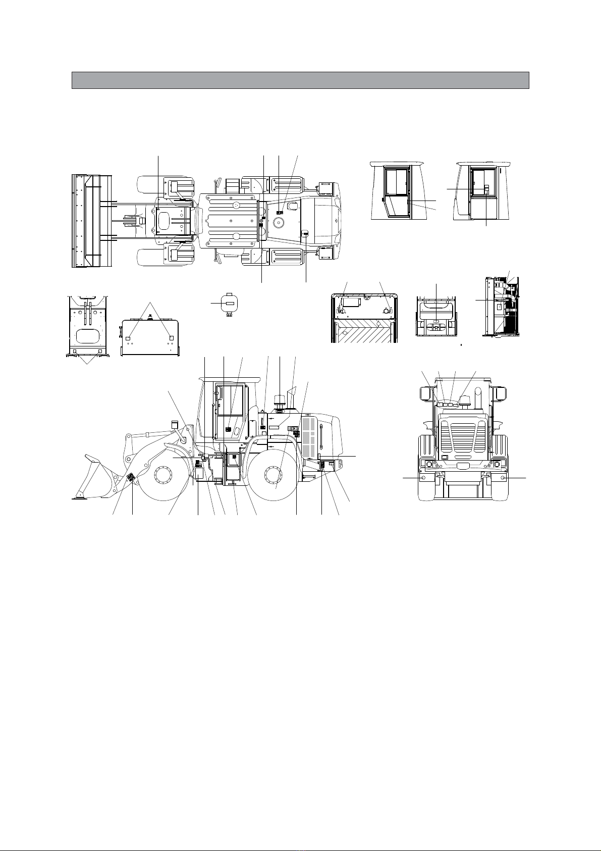
Safety labels
------------------------------------------------------
0-6
Machine data plate
--------------------------------------------
0-16
Guide (direction, S/No, symbol)
------------------------
0-17
1. SAFETY HINTS
1. California proposition 65
----------------------------
1-1
2. Safety rules
------------------------------------------------
1-2
2. SPECIFICATIONS
1. Major components
--------------------------------------
2-1
2. Specifications
----------------------------------------------
2-2
3. Weight
---------------------------------------------------------
2-6
4. Specification for major components
-----------
2-7
3. CONTROL DEVICES
1. Cab devices
------------------------------------------------
3-1
2. Cluster
--------------------------------------------------------
3-2
3. Monitors
------------------------------------------------------
3-13
4. Switches
-----------------------------------------------------
3-44
5. Control device
---------------------------------------------
3-49
6. Air conditioner and heater
--------------------------
3-53
7. Others
---------------------------------------------------------
3-56
4. OPERATION
1. Suggestion for new machine
----------------------
4-1
2. Check before starting the engine
---------------
4-2
3. Starting and stop the engine
----------------------
4-3
4. Warming-up operation
--------------------------------
4-8
5. Operation of the working device
-----------------
4-9
6. Traveling of the machine
-----------------------------
4-10
7. Efficient working method
----------------------------
4-15
8. Adjustment of the work equipment
-------------
4-22
9. Operation in the special work sites
-------------
4-23
10. Storage
--------------------------------------------------------
4-25
11. Exhaust system cleaning
-----------------------------
4-27
12. Attachment manually lowering
----------------------
4-28
5.
TRANSPORTATION
1. Road traveling
--------------------------------------------
5-1
2. Preparation for transportation
--------------------
5-2
3. Loading the machine
---------------------------------
5-3
4. Fixing the machine
-------------------------------------
5-4
5. Loading and unloading by crane
----------------
5-6
6.Towing the machine
-------------------------------------
5-7
6. MAINTENANCE
1. Instructions
-------------------------------------------------
6-1
2. Tightening torque
---------------------------------------
6-5
3. Spec of fuel, coolant and lubricants
-----------
6-8
4. Maintenance check list
-------------------------------
6-10
5. Maintenance chart
-------------------------------------
6-13
6. Service instruction
-------------------------------------
6-15
7. Electrical system
----------------------------------------
6-54
8. Air conditioner and heater
--------------------------
6-57
7. TROUBLESHOOTING GUIDE
1. Engine
--------------------------------------------------------
7-1
2. Electrical system
----------------------------------------
7-2
3. Power train system
---------------------------------------
7-3
4. Hydraulic system
----------------------------------------
7-4
8. OTHERS
1. Quick coupler
---------------------------------------------
8-1
INDEX
-------------------------------------------------------------
9-1