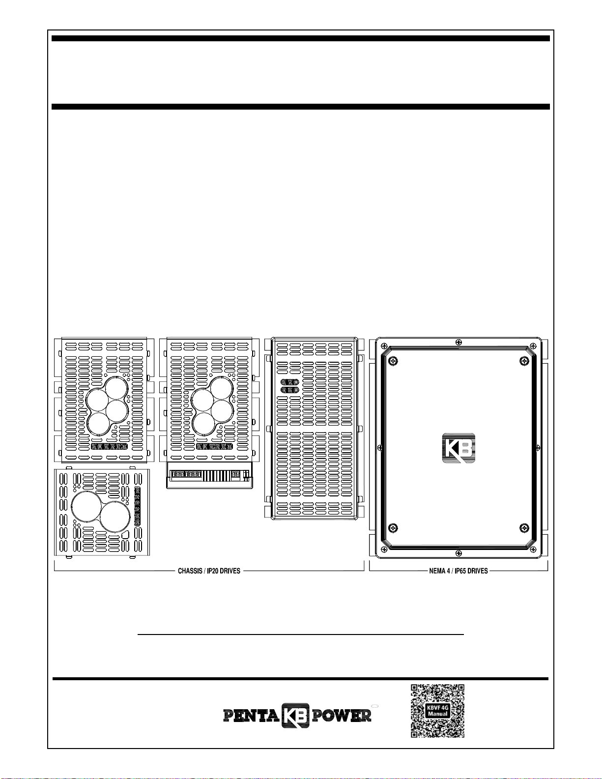
– KBVF 4G SERIES INSTALLATION AND OPERATION MANUAL –
TABLE OF CONTENTS (CONTINUED)
Table Page
1 Electrical Ratings ........................................................................................................................................................................................ 9
2 General Performance Specifications ......................................................................................................................................................... 10
3 Terminal Block Wire Size and Tightening Torque Specifications ............................................................................................................... 14
4 Drive Operating Condition and Run/Fault Relay Contact Status ................................................................................................................ 17
5 Fault Recovery and Resetting the Drive .................................................................................................................................................... 19
6 Drive Operating Condition and Status LED Indicator ................................................................................................................................. 21
7 RS-485 Specifications ............................................................................................................................................................................... 21
Figure Page
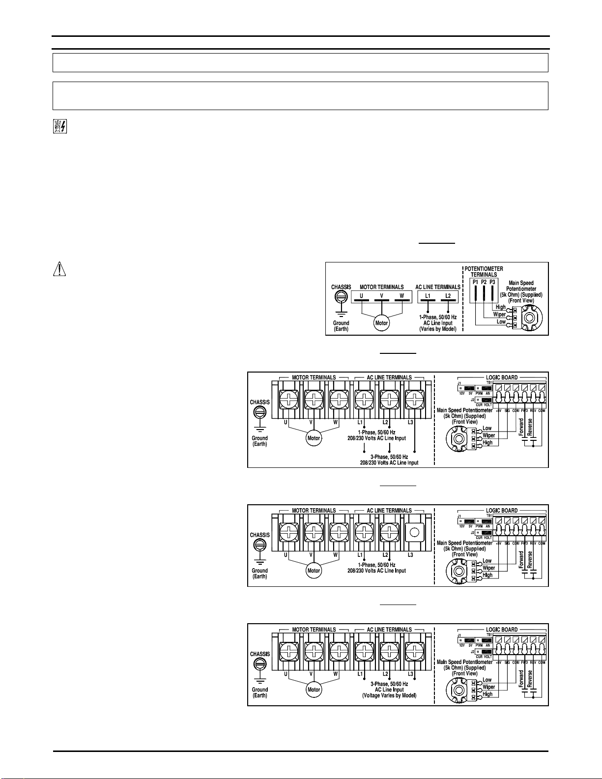
1 KBVF-13, 14, 21D, 22D, 23, 23D, 24, 24D, 26D General Connections Diagram .......................................................................................... 4
2 KBVF-27, 27E, 27EF, 29, 29E, 29EF, 29EF (1P) General Connections Diagram ........................................................................................ 4
3 KBVF-29 (1P) General Connections Diagram.............................................................................................................................................. 4
4 KBVF-42, 42E, 42EF, 45, 45E, 45EF, 48, 48E, 48EF General Connections Diagram .................................................................................. 4
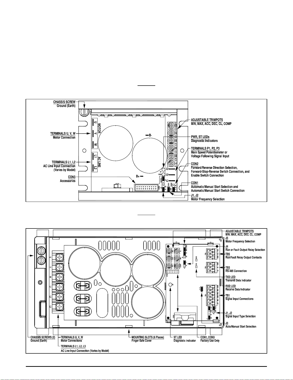
5 KBVF-13, 14, 21D, 22D, 23, 23D, 24, 24D, 26D Drive Layout ..................................................................................................................... 7
6 KBVF-27, 29, 29 (1P), 42, 45, 48 Drive Layout ............................................................................................................................................ 7
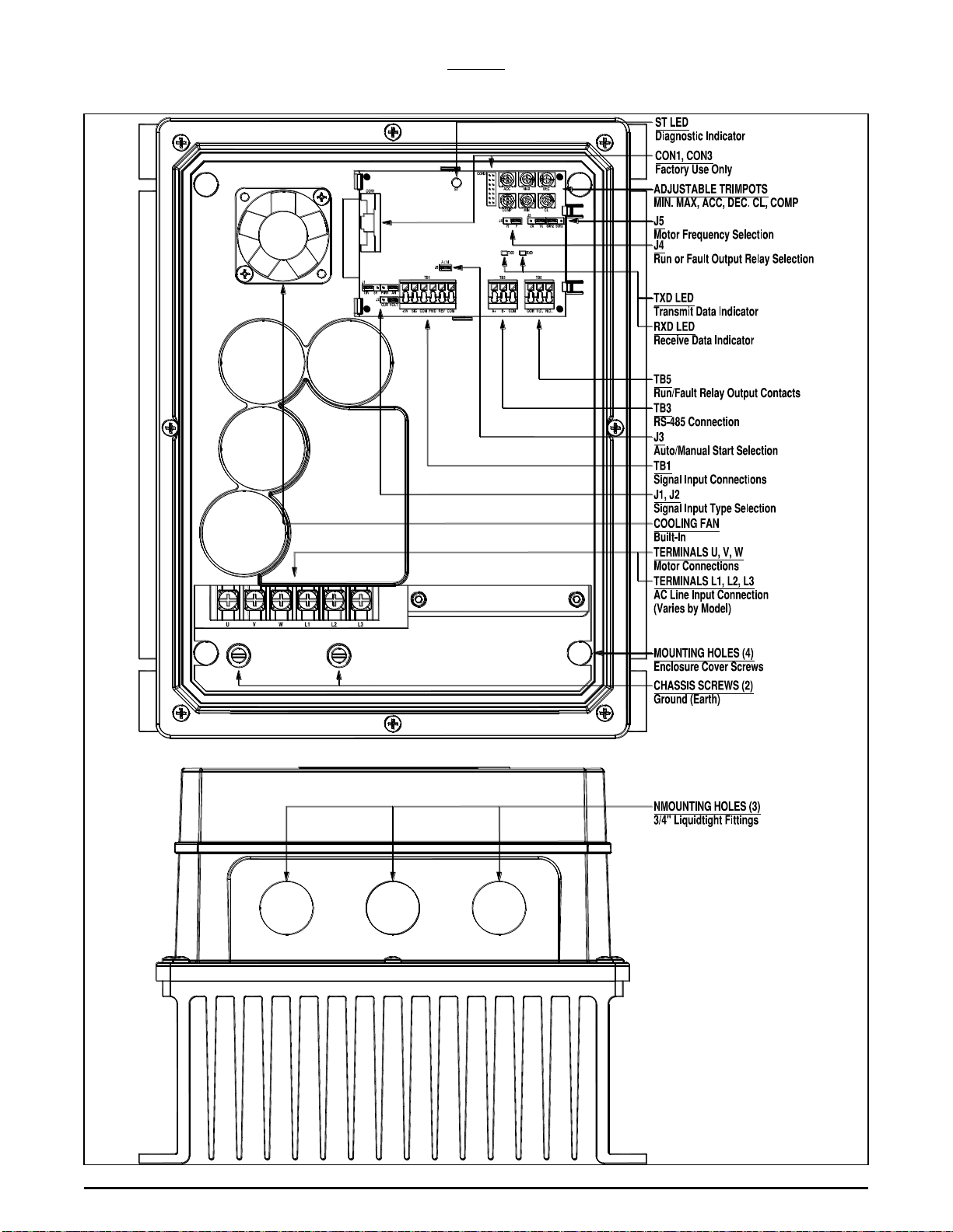
7 KBVF-27E, 27EF, 29E, 29EF, 29EF (1P), 42E, 42EF, 45E, 45EF, 48E, 48EF Drive Layout ........................................................................ 8
8 KBVF-13, 21D, 22D, 23, 23D Mechanical Specifications ........................................................................................................................... 11
9 KBVF-14, 24, 24D, 26D Mechanical Specifications ................................................................................................................................... 12
10 KBVF-27, 29, 29 (1P), 42, 45, 48 Mechanical Specifications ..................................................................................................................... 12
11 KBVF-27E, 27EF, 29E, 29EF, 29EF (1P), 42E, 42EF, 45E, 45EF, 48E, 48EF Mechanical Specifications ................................................. 13
12 KBVF-13, 14, 21D, 22D, 23, 23D, 24, 24D, 26D AC Line Input, Motor, and Ground Connections .............................................................. 14
13 KBVF-27, 27E, 27EF, 29, 29E, 29EF AC Line Input, Motor, and Ground Connections .............................................................................. 14
14 KBVF-29 (1P), 29EF (1P) AC Line Input, Motor, and Ground Connections ................................................................................................ 15
15 KBVF-42, 42E, 42EF, 45, 45E, 45EF, 48, 48E, 48EF AC Line Input, Motor, and Ground Connections ...................................................... 15
16 KBVF-13, 14, 21D, 22D, 23, 23D, 24, 24D, 26D Main Speed Potentiometer Connection ........................................................................... 15
17 KBVF-27E, 27EF, 29E, 29EF, 29EF (1P), 42E, 42EF, 45E, 45EF, 48E, 48EF Main Speed Potentiometer Connection ............................. 15
18 KBVF-13, 14, 21D, 22D, 23, 23D, 24, 24D, 26D Voltage Following Connections ....................................................................................... 15
19 KBVF-27E, 27EF, 29E, 29EF, 29EF (1P), 42E, 42EF, 45E, 45EF, 48E, 48EF Voltage Following Connections ......................................... 15
20 KBVF-27E, 27EF, 29E, 29EF, 29EF (1P), 42E, 42EF, 45E, 45EF, 48E, 48EF Current Following Connections .......................................... 16
21 Manual Start Switch Connection ................................................................................................................................................................ 16
22 KBVF-13, 14, 21D, 22D, 23, 23D, 24, 24D, 26D Forward-Stop-Reverse Switch Connection ..................................................................... 16
23 KBVF-27E, 27EF, 29E, 29EF, 29EF (1P), 42E, 42EF, 45E, 45EF, 48E, 48EF Forward-Stop-Reverse Switch Connections ...................... 16
24 KBVF-13, 14, 21D, 22D, 23, 23D, 24, 24D, 26D Enable Switch Connection .............................................................................................. 16
25 KBVF-27E, 27EF, 29E, 29EF, 29EF (1P), 42E, 42EF, 45E, 45EF, 48E, 48EF Enable Switch Connection ................................................. 16
26 Run/Fault Relay Output Contacts Connection ........................................................................................................................................... 17
27 Typical Hi-Pot Test Setup .......................................................................................................................................................................... 17
28 KBVF-21D, 22D, 23D, 24D AC Line Input Voltage Selection ..................................................................................................................... 18
29 KBVF-26D AC Line Input Voltage Selection .............................................................................................................................................. 18
30 KBVF-13, 14, 21D, 22D, 23, 23D, 24, 24D, 26D Motor Frequency Selection ............................................................................................. 18
31 KBVF-27E, 27EF, 29E, 29EF, 29EF (1P), 42E, 42EF, 45E, 45EF, 48E, 48EF Motor Frequency Selection ................................................ 18
32 Available Torque vs. Output Frequency ..................................................................................................................................................... 18
33 Automatic Start.......................................................................................................................................................................................... 18
34 KBVF-13, 14, 21D, 22D, 23, 23D, 24, 24D, 26D Forward/Reverse Speed Selection ................................................................................. 19
35 KBVF-27, 27E, 27EF, 29, 29E, 29EF, 29EF (1P), 42, 42E, 42EF, 45, 45E, 45EF, 48, 48E, 48EF Run/Fault Relay Operation Selection ... 19
36 Analog or PWM Signal Input Selection ...................................................................................................................................................... 19
37 5 Volt DC or 10 Volt DC Signal Input Selection .......................................................................................................................................... 19
38 Voltage or Current Signal Input Selection .................................................................................................................................................. 19
39 MIN Trimpot Range ................................................................................................................................................................................... 19
40 MAX Trimpot Range .................................................................................................................................................................................. 19
41 ACC Trimpot Range .................................................................................................................................................................................. 19
42 DEC Trimpot Range .................................................................................................................................................................................. 20
43 COMP Trimpot Range ............................................................................................................................................................................... 20
44 CL Trimpot Range ..................................................................................................................................................................................... 20
45 I2t Trip Time vs. Motor Current .................................................................................................................................................................. 20
GFCI DISCLAIMER
The drives are tested and designed to operate with standard and sensitive GFCIs. This ensures that our drives will operate with most GFCIs.
Motor characteristics, wire lengths, etc., may affect system performance with GFCIs. Therefore, to verify that your GFCI will operate with our
drive and in your application, it is highly recommended that you contact our Technical Support team with information about your application
and your specific GFCI. To read our online white paper on GFCIs: Click Here
UL NOTICE FOR KBVF-13, 14, 21D, 22D, 23, 23D, 24, 24D, 26D
115 Volt Drives: Suitable for use on a circuit capable of delivering not more than 5 kA RMS symmetrical Amperes. 115 Volts maximum.
Use copper conductors rated 75 °C. Suitable for operation in a maximum surrounding air temperature of 40 °C.
230 Volt Drives: Suitable for use on a circuit capable of delivering not more than 5 kA RMS symmetrical Amperes. 230 Volts maximum.
Use copper conductors rated 75 °C. Suitable for operation in a maximum surrounding air temperature of 40 °C.
UL NOTICE FOR KBVF-27, 27E, 27EF, 29, 29 (1P), 29E, 29EF, 29EF (1P), 42, 42E, 42EF, 45, 45E, 45EF, 48, 48E, 48EF
230 Volt Drives: Suitable for use on a circuit capable of delivering not more than 5 kA RMS symmetrical Amperes. 230 Volts maximum.
Use copper conductors rated 75 °C. Suitable for operation in a maximum surrounding air temperature of 50 °C.
460 Volt Drives: Suitable for use on a circuit capable of delivering not more than 5 kA RMS symmetrical Amperes. 460 Volts maximum.
Use copper conductors rated 75 °C. Suitable for operation in a maximum surrounding air temperature of 50 °C.