Optional accessories inclu e On/Off AC Line Switch, FWD-BRK-REV Switch, Run-Stop-Jog
Switch, Signal Isolator, an Anti-Plug Reversing Mo ule. Quick-connect terminals are provi -
e for easy installation of all optional accessories. The control is available in black finish (P/N
8401) an FDA approve white finish (P/N 8402).
STANDARD FEATURES
•Short Circuit Protectio – Protects control from a short circuit at motor connections.
•Electro ic Motor Bur out Protectio – Time Current Limit shuts own the control if a pro-
longe overloa con ition exists.
•Active Bridge – Limits the AC line inrush current when power is turne on an also prevents
high spee runaway if the power transistor shorts.
•Heat Spreader – Allows power transistor to operate safely uring momentary overloa con i-
tions.
•Auto AC Li e Select – Control automatically a justs for 115 or 208/230 Volt AC line input.
•Start/Stop Switch – Provi es electronic start an stop functions.
•Diag ostic LEDs – For power on (ON), stop (STOP) an motor overloa (OL).
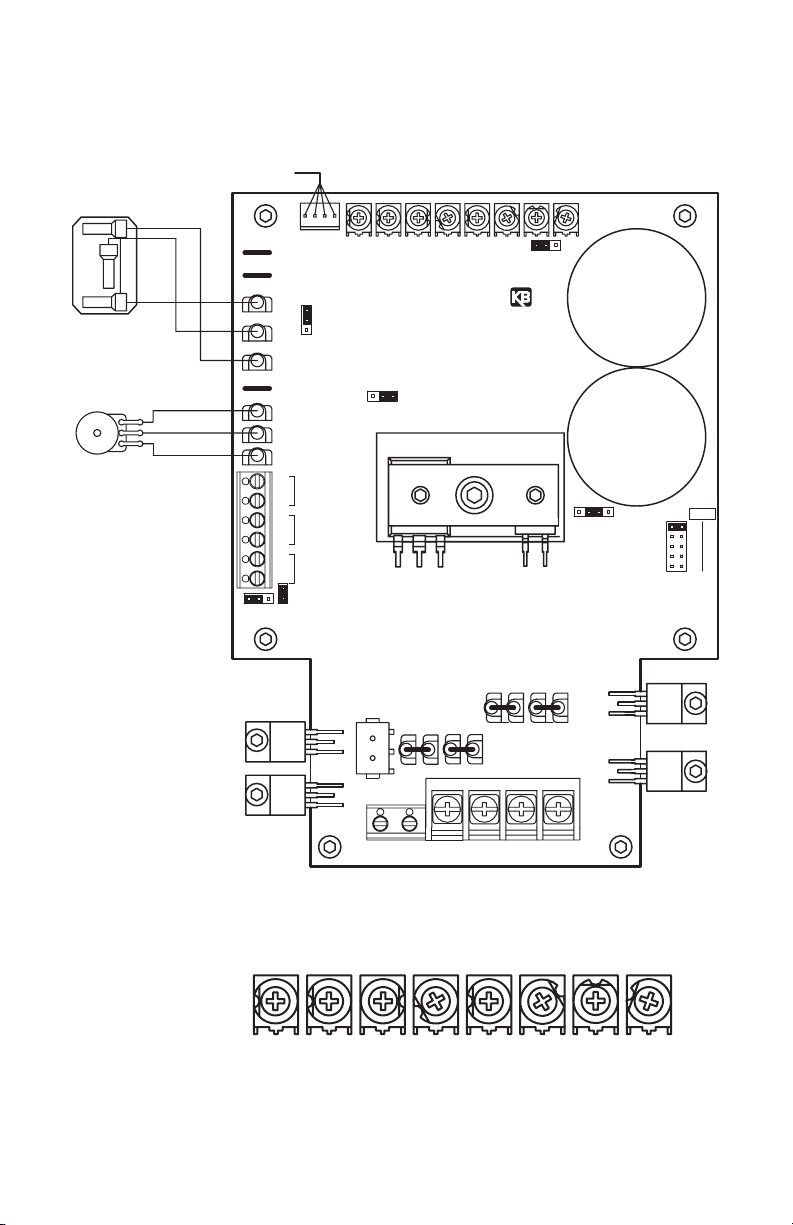
•Trimpots – Provi e a justment for acceleration (ACCEL), eceleration (DECEL), maximum
spee (MAX), minimum spee (MIN), jog spee (JOG), current limit (CL), time current limit
(TCL), an IR compensation (IR).
•Selectable Jumpers – Provi e settings for armature voltage or tach-generator fee back (J1),
motor current (J2), time or non-time current limit (J3), tach-generator voltage (J4), an run
relay output (J5).
•Barrier Termi al Blocks – Facilitate wiring of AC line, motor armature an fiel , tach-genera-
to, run relay output, an thermal or enable switch.
•Quick-Co ect Termi als – Facilitate connecting Start/Stop switch, Run-Stop-Jog switch,
FWD-BRK-REV switch, an Inhibit switch.
II. SIMPLIFIED OPERATING INSTRUCTIONS
A. Power Co ectio – Connect the AC line to L1 an L2 terminals of TB1 an the groun
wire (Earth) to the green groun screw as shown in Figure 3, on page 6, an as escribe
in Section IIIA, on page 6, an Section IIIB, on page 6.
B. Perma e t Mag et (PM) Motor Co ectio (Two-Wire Type) – Connect the motor arma-
ture to A1 (+) an A2 (-) terminals of TB1 as shown in Figure 3, on page 6, an as escribe
in Section IIIC, on page 6. Be sure that jumper J3 is set to the correspon ing motor voltage
position as escribe in Section IVA, on page 10. Do ot use F1 a d F2 termi als of TB2
for a y purpose other tha to power the field of a shu t wou d motor. Do ot use F1
a d F2 termi als for PM motors.
Note: Motor performance an efficiency, inclu ing brush life, may be a versely affecte
when operating the control in step own mo e (208/230 Volt AC line with 90/130 Volt DC
motors).
C. Shu t Wou d Motors (Four-Wire Type) – Connect the motor armature as escribe in
Section IIIC, on page 6. Connect full voltage fiel wires (90 Volt DC motors with 100 Volt
DC fiel an 180 Volt DC motors with 200 Volt DC fiel ) to F1 (+) an F2 (-) terminals of TB2
as escribe in Section IIID, on page 7. Connect half voltage fiel wires (90 Volt DC motors
with 50 Volt DC fiel an 180 Volt DC motors with 100 Volt DC fiel ) to F1 (+) terminal of
TB2 an L1 (-) terminal of TB1 as escribe in Section IIIE, on page 7.
Note: Do not connect motor armature lea s to F1 an F2 terminals.
2
IMPORTANT – You must rea these simplifie operating instructions before procee ing.
These instructions are to be use as a reference only an are not inten e to replace the
etaile instructions provi e herein. You must rea the Safety Warning, on page 1, before
procee ing.