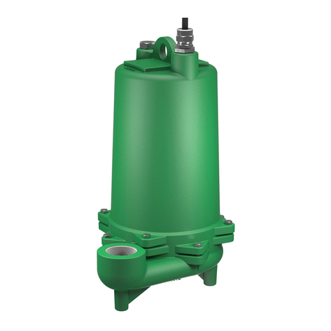
Pump:
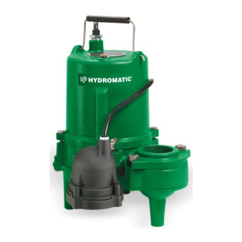
The S3R submersible pump is sup-
plied for 1 and 3 phase and for 200,
230, 460 or 575 volts. Power cable
is supplied with the green wire for
ground. Be sure the green wire is
connected to a good ground such as
water pipe or groundstake.
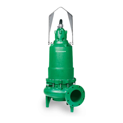
The S3RX submersible pump is
supplied for 1 and 3 phase and for
200, 230, 460 or 575 volts. Pump is
supplied with 35 feet of power cord
and/or 35 feet of auxiliary control
cord. Longer cable lengths can be
furnished but must be specified at
time of order. Power cable is 4 wire
with the green wire for ground. Be
sure the green wire is connected to a
good ground such as water pipe or
a ground stake. The auxiliary cable
for seal failure and heat sensors is
also 4 wire colorcoded.
Heat Sensors:
All motors have heat sensor units
embedded in the motor winding to
detect excessive heat. The heat
sensors are set to trip at 120°C. The
sensors automatically reset when
motor cools to safe temperature.
The sensors are connected in
series with the motor starter coil
so that the starter is tripped if heat
sensor opens. The motor starter is
equipped with overload heaters so
all normal overloads are protected by
thestarter.
IMPORTANT: If Hydromatic electrical
starting equipment is not supplied,
the heat sensor circuit must be
connected in series with the starter
coil or warranty isvoid.
Sump Level Control:
Sump level is controlled by
Hydromatic switch controls. The
float is held in position in the sump
by a weight attached to the power
cord above the float. The cord
supports the float and is adjusted for
height from thesurface.
Duplex systems use three controls:
one set at turn-off, one set at
3
turn-on for one pump, and one
set for turn-on for two pumps.
Pumps alternate operation on each
successivecycle.
Two pumps operate together only
if sump level rises to the third or
override control. The override
control also brings on the second
pump in case of failure of the first
pump. Extra floats with appropriate
controls can be supplied for alarm
functions. Triplex systems use four
controls: one set at turn-off, one set
at turn-on for one pump, one set at
turn-on for two pumps, and one set
at turn-on for three pumps. Pumps
alternate each successivecycle.
Three pumps operate together only
if sump level rises to the fourth
control (second override). This
control also brings on the third pump
in case of failure of either or both of
the first twopumps.
Installing Sump Level Control
FloatControls:
In either simplex, duplex or triplex
systems the lower or turn-off control
is to be set to maintain a minimum
level in the sump. This level shall
be no more than 31⁄4" from the top
of the motor housing down to the
surface of thesewage.
The second or turn-on control is set
above the lower turn-off control.
The exact distance between the
two floats must be a compromise
between a frequent pumping cycle
(10 starts per hour max.) to control
septicity, solids and a slower cycle
for energy economy. This distance
should be determined by the
engineer or consulting engineer,
depending on the conditions of
theapplication.
For installation of Hydromatic
supplied level controls, refer to
your system’s installation and
servicemanual.
Alarm Controls:
The alarm level is usually set above
the override level so the alarm will
signal only if the override level is
exceeded. However, some engineers
prefer to have the alarm level set
below the override level as it is
possible for one pump to fail and
the other pump to operate on the
override level with the sump level
never reaching the alarm level. This
is particularly true in cases of low
inflowcapacity.
Electrical Control Panel:
It is recommended that the
Hydromatic control panel be used
with all pumps as proper starter
heaters and connections for heat
sensor wires arefur nished.
IMPORTANT: If Hydromatic®
electrical controls are not used and
the motor fails because of improper
components or if the heat sensors
are not properly connected the
warranty isvoid.
Hydromatic electrical equipment is
installed in a weatherproof NEMA 3R
enclosure. The electrical equipment
includes a main circuit breaker for
each pump, a magnetic starter with
overload protection for each pump,
an H-O-A switch and run light for
each pump, an electric alternator
and a transformer to provide ap-
propriate control for control circuit
andalarms.
Overload Heaters:
Starters with 3 leg overload
protection must be supplied if the
Hydromatic electrical panel is not
used. The heaters must be sized
in accordance with the nameplate
amps on the motor. The amp draw
on these submersible motors is
slightly higher than a corresponding
horsepower surface motor, so
heaters must be sized by the
nameplaterating.
IMPORTANT: Make certain the heat
sensor wires are connected in series
with the starter coil circuit if other
than Hydromatic starters areused.
