MGF 904 Series User manual

The present manual has been realised, where possible, in accordance with Rule 98/37/CE "Direttiva
acchine", 2006/42/CE "Nuova Direttiva acchine" UNI Rule 10893 "User instruction - “order of contents”.
Art. 904XXX
High Pressure
Test Pump
User Manual
rev. 1.0 del 12/02/2014

Introduction
Introduction
This manual, supplied with the pump and remaining installation material pipes, nozzles, fittings, electronics,
tools...) provides important informations about the correct installation, use and maintenance.
Read this manual carefully to respect all the directives provided, are important conditions for
warranty validity and correct use and functioning of the whole system.
The installer must inform the end user about the correct use of the system.
The manufacturer declines every responsibility for damages caused by wrong installation, or misuse
of the system.
General Informations
General Informations
ACHINE TECHNICAL DATA
Find out the label on the machine providing the informations about technical data
TECHNICAL ASSISTANCE
call number: +39521818301 4 lines)
fax: +39521818202
email: [email protected]
Shipment of defective parts must be authorized by MGF RMA module. Otherwise we cannot accept arriving
goods.
WARRANTY TER S
Warranty on these machines is on every manufacturing defect for a time of 2 years from manufacturing.
Manufacturing time is indicated on label on the pump.
The warranty doesn't cover:
–Consumable parts: nozzles, gaskets, orings after first run installation and test.
–Problems caused by misuse
–Bad maintenance
–Machines or parts modified or changed
MGF is not responsible besides for damages caused by: system stop lost of productivity, plant stops...), misting
of dangerous liquids or polluted water, vandalisms.
The warranty doesn't cover substitution damages, since MGF is not the installation maker.

High pressure pipe available on demand
904900
904800
904700
Art.
CARATTERISTICHE TECNICHE COMUNI
1000 bar
500 bar
300 bar
Pressure
1/2” GAS
A
800mm
B
800mm
C
400mm
D
500mm
E
400mm
F
50Kg
weight
RELEASE LEVER 1° / 2° STAGE

Assembly and Operating Instructions
Assembly and Operating Instructions
High pressure test pumps are easy to use and can be used by anyone without undue fatigue.
Pumps should be assembled as follows, using PTFE tape on all threads to ensure air tight connections.
1. Screw suction pipe into the base of the pump.
2. Mount the pump on the bridge of the tank.
3. Screw in the valve unit, ensuring the connection hole for the gauge tube is opposite the outlet and is
vertical.
4. Screw the gauge tube.
5. Mount gauge.
6. Connect hose.
7. Check all connections are tight.
8. Fill tank with enough water, or oil mixed with water, to cover suction pipe inlet and check pump operation.
9. Connect the pump to the appliance.
10. If necessary re-seal any threads which show signs of leakage.
11. If pump refuses to prime, pour liquid into the outlet to wet the valve area.
12. To start test, close the discharge valve and open the flow-valve. There are two handwheels on the control
valve block for these two valve. A light alternating movement of the handle creates a steady flow of liquid
after a few initial priming strokes; keep up the movement which gradually becomes stiffer until the desired
pressure is read on the gauge.
13. Next close the discharge valve, isolating the appliance being tested. To end the operation, open both
valves and surplus liquid will run back into the tank via the drain hole in the valve control block.
Instructions for Use
Instructions for Use
Manual hydraulic high pressure test pump are piston type, two-stage high and low pressure), self-priming and
double acting.
ASSE BLY
Before you start any operation of pump, make sure that all the accessories has been fitted correctly: suction tube
with nut and filter, manual lever, pressure gauge and pressure gauge supply, delivery hose for high pressure
usually not included).
In order to favour the immediate reading during the test, orient the pressure gauge in the direction of the
operator. Remember to apply the seals necessary to all components.
Since there are threads, it will be necessary to interpose those products that prevent any leakage: PTFE Teflon)
tape or in liquid or fillets paste.

CONNECTION TO THE APPLIANCE TO BE TESTED
After screwing the delivery hose to the pump, connect the same to the appliance to test pipe, tank, valve, etc..),
paying attention to the "hydraulic seal".
FILL UP THE APPLIANCE TO BE TESTED
Whatever is the appliance to test, it has to be filled up in advance with the same liquid that will be used for the
test.
FILLING THE TANK
The pump has a tank with a capacity of 100 liters. Fill up the tank making sure the suction tube is completely
submerged. Use a mixture of water and emulsifiable oil in order to prevent oxide formation inside the machine.
If you can not find the liquid, use water or common oil.
SAFETY
Before shipment, all the pumps are tested in firm, are tough and very robust and therefore very safe.
The operator should wear gloves and protective screen, and people not involved with the testing should leave test
bench.
FIRST STAGE
The machine has two coaxial pistons. The first piston in action is the brass one, with a larger diameter. For this
purpose, verify that the release lever is adjacent to the pump body.
Check that the drain flyer is tight, otherwise close it turning in a clockwise way.
Pumping moving the lever from the bottom on the top. Due to the low flow rate, the pressure gauge will not
begin to rise immediately, but after a few cycles.
The pump is self - priming, so it will come into operation by taking the fluid from the tank below and sending it in
the appliance to be tested.
When you reached 100/120 bar, skip to second stage.
SECOND STAGE
Place the release lever in opening position at 90° respect the pump body), to position the brass piston with
greater diameter and to free the steel piston with smaller diameter. This piston allows the attainment of high
pressures.
Pumping regularly and quickly, moving the lever from the bottom on the top.
Check the pressure shown in the gauge, and do not exceed the maximum pressure.
DISCHARGE THE PRESSURE
At the end of the test, you will have to relieve the pressure acting on the flyer's tap that is on the side of the
pump body. Turning in anticlockwise way the faucet opens the valve by draining the emulsifiable oil or water)
through the drain hole, located under this tap.
From this hole ejects the liquid to the tank below.

Maintenance
Maintenance
Periodically lubricate the piston, clean the suction filter and valves.
Periodically check the pipe.
Use original parts and accessories and make do the repair by qualified personnel.
If you decide not to use the machine, it is recommended to keep it in any case out of the reach of children.
In case of scrapping, disassemble the machine and collect the homogeneous parts for disposal in accordance with
local regulations.
Do not use the parts scrapped as spare parts.
Warnings
Warnings
•Use the pump only for the purpose for which it is intended and in full compliance with the general safety
regulations. Be sure that the machine and all its parts are placed out of reach of children. Keep clean and
well lit work area.
•Position the pump so that the filling of the system can be in operated safety. Do not use the pump resting
on uneven surfaces or horizontal. Avoid working in hazardous environments eg, in the presence of
flammable liquids or gases).
•Use a clothing appropriate to the work to be performed. Do not use loose clothing, long hair pick, remove
rings and necklaces.
•Ensure that there is an optimal grip of the handle. Do not work with greasy hands, if necessary, clean the
handle before using the pump.
•Noise level during use is less than 80dbA
The manufacturer declines all responsibility for any damage that may arise from non-compliance
with the intended use, the instructions and warnings contained in this document.
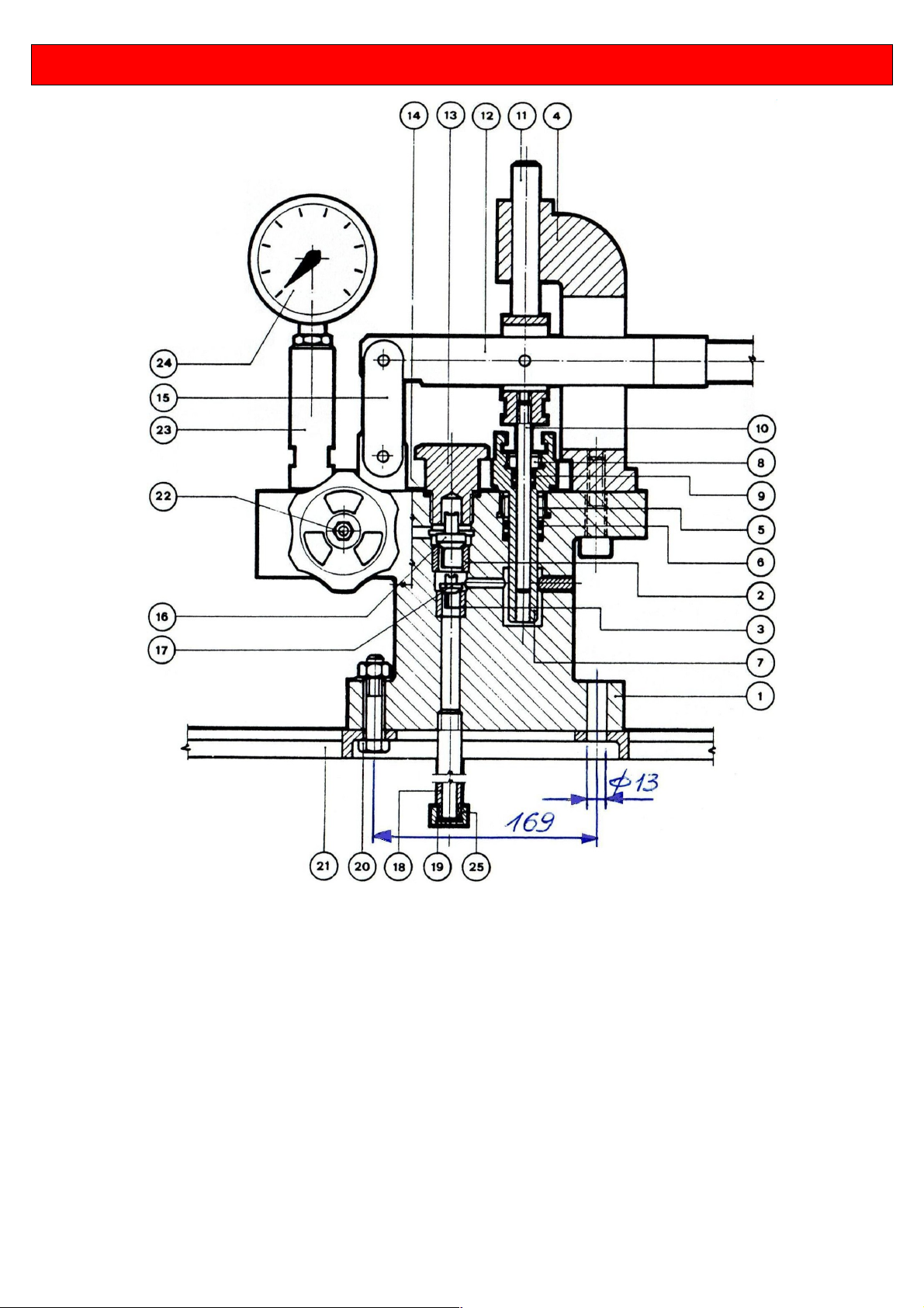
Spare Parts
Spare Parts
Pos. Description Pos. Description
1 Body pump 14 Seal cap
2 Seat upper shutter 15 Joint
3Seat lower shutter 16 Higher shutter
4 Support 17 Lower shutter
5 Large packing gasket 18 Suction tube
6 Seal for large piston 19 Stainless steel filter
7 Large piston 20 Bolt
8 Small packing gasket 21 Tank
9 Seal for small piston 22 Faucet
10 Small piston 23 Gauge holder
11 Guide for piston 24 Pressure Gauge
12 Lever with handle 25 Filter cap
13 Plug

Table of contents
Other MGF Water Pump manuals


