9
Maintenance
Make certain
that the unit is
disconnected from the power source before
attempting to service or remove any com-
ponents!
REMOVAL OF OLD SEAL ASSEMBLY
Should the mechanical seal (Ref. No. 5)
require repair, proceed as follows and
refer to Figures No. 2 thru 7.
IMPORTANT: Always replace both the
seal seat and seal as an assembly to
ensure proper mating of components!
1. Remove bolts (Ref. No. 12) connect-
ing the casing housing (Ref. No. 9)
to the body (Ref. No. 4).
2. Remove the casing housing (Ref.
No. 9).
Care should be taken
not to pinch or
”shave” the o-ring
gasket (Ref. No. 8) between the body and
the casing housing.
3. Remove the impeller (Ref. No. 7).
NOTE: Pump shaft must be held in
place to remove impeller.
IMPORTANT: Care should be taken to
ensure that the same number and
thickness of shim washers (Ref. No. 6)
are replaced behind the impeller as was
removed. The shim washers are located
directly behind the impeller and become
loose as the impeller is removed.
4. The seal (part of Ref. No. 5) can
now be pulled from the shaft
(see Figure 4).
5. Remove the retaining ring (Ref. No. 1)
and press the shaft assembly (Ref.
No. 2) out of the body. Take care not
to damage the impeller threads.
6. Use a wooden dowel to push out the
seal seat (part of Ref. No. 5) from the
body (Ref. No. 4). (See Figure 5.)
INSTALLATION OF NEW SEAL ASSEMBLY
The precision
carbon/ceramic faces
on the mechanical seal are easily damaged.
Handle your repair seal carefully. Do not
touch the carbon/ceramic seal faces.
IMPORTANT: Be sure that shaft
shoulder does not damage carbon face.
1. Thoroughly clean all surfaces of the
seal seat cavity in body (Ref. No. 4).
2. Using a clean cloth, wipe the shaft
and shaft sleeve and make certain
that they are perfectly clean.
NOTE: Inspect the shaft for scratches
or spiral grooves. If they exist, replace
shaft assembly (Ref. No. 2).
3. Wet the rubber portion of the new
seal seat (part of Ref. No. 5) with a
light coating of soapy water. While
wearing clean gloves or using a
clean light rag, press seal seat
squarely into body recess (Ref. No.
4). Use the cardboard washer (usu-
ally supplied with new seal) to place
over the polished ceramic surface
and use a piece of pipe or dowel
rod to press in firmly but gently (See
figure 6). Avoid scratching the
ceramic face, usually white.
4. Dispose of cardboard washer.Check
again to see that ceramic surface is
free of dirt and all other foreign
particles and that it has not been
scratched or damaged.
5. Install the pump shaft assembly
(Ref. No. 2). Replace the retaining
ring (Ref. No. 1). Be careful not to
damage the seal seat when sliding
over the pump shaft.
6. Wet the inside rubber portion of
the new seal (part of Ref. No. 5)
with a light coating of soapy water.
Slide seal onto the pump shaft
with the precision sealing surface
(carbon) facing the seal seat
ceramic face (see Figure 7). This
completes seal installation.
NOTE: Ashort “run-in” period may be
necessary to provide completely
leakproof seal operation.
7. Screw impeller (Ref. No. 7) onto
shaft. To hold the shaft from
turning, clamp with a web wrench
to prevent marring the shaft. A
drop of removable thread lock
should be applied to the impeller
threads. Impeller should be torqued
to 15 to 18 ft-lbs. (180 to 210 in-
lbs.).
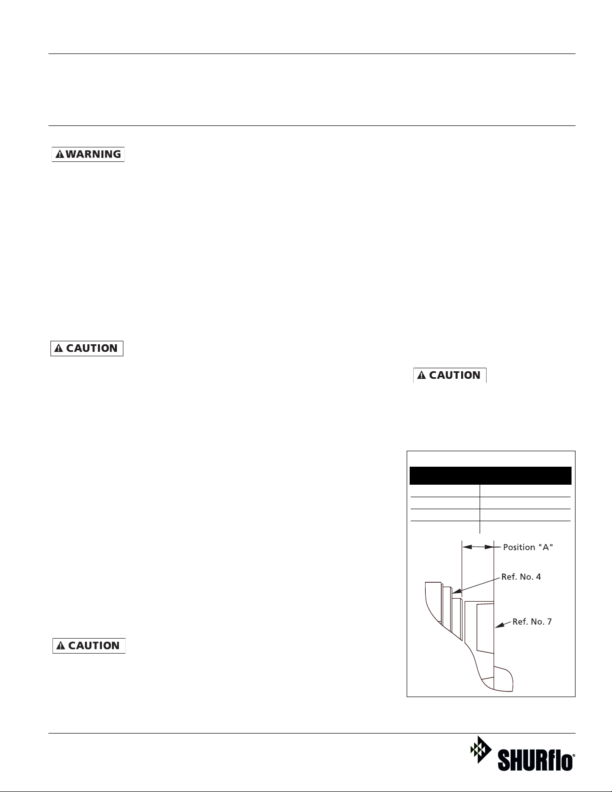
8. By replacing the original shims that
came with the pump, the impeller
height should be properly set. The
chart accompanying figure 3 gives
the correct body to impeller height
dimension for optimum pump
performance. After installing, check
if shaft turns freely by spinning
impeller. If rubbing or binding is
found, remove impeller and add a
shim (Ref. No. 6) to shaft, then
recheck. Repeat procedure until all
rubbing is eliminated.
9. Place o-ring (Ref. No. 8) on pump
body. Attach housing (Ref. No. 9)
using bolts (Ref. No. 12) being care-
ful not to pinch or “shave” o-ring.
As the housing is being tightened,
periodically spin impeller to check
for interference with housing.
Seal assembly will produce minor
drag when spinning drive shaft, but rub-
bing anywhere else must be eliminated!
Otherwise, damage to pump and/or motor
may occur.
SHURflo Operating Instructions, Performance,
Specifications and Parts Manual
Impeller # Position “A”
1 0.634"-0.674"
3 0.742"-0.782"
5 0.874"-0.914"
7 0.840"-0.870"
Figure 3
IMPELLER CLEARANCE DIMENSIONS
316 Stainless Steel, Bronze and Cast Iron Models
Form L-4075 (12/09)


