Pentair Pool Products CodeLine 40E30N Series User manual

Product Bulletin 526003 Rev. B
This vessel may cause loss of life, severe bodily harm, or property damage if not correctly installed, operated and
maintained. Read and understand all guidelines given in this bulleting before attempting to open, operate or service
this vessel. Failure to follow these guidelines and observe every precaution will result in malfunction and could
result in catastrophic failure. Misuse, incorrect assembly, or use of damaged or corroded components can result
in high-velocity release of the end closure. We recommend that only a qualified technician experienced in servicing
high-pressure hydraulic systems open, close and service this vessel.
TM
CodeLine 40E30N Series
User’s Guide
DANGER - HIGH PRESSURE DEVICE
Important Safety Precautions
General Information
read, understand and follow every guide-
line in this bulletin. Failure to take every
precaution may void warranty and could
result in catastrophic failure.
Do...
install in an area where a vessel or piping
malfunction that result in water leakage
would not damage sensitive or expensive
equipment, such as electronic components.
Do...
verify that head locking components are
properly placed and secured.
Do...
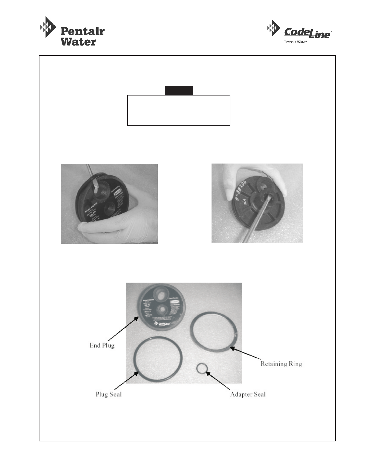
inspect end closures regularly, replace
deteriorated components and correct
causes of corrosion.
Do...
follow membrane element manufacturer’s
recommendations for loading elements into
the vessel (see Replacing Elements).
Do...
operate vessel at pressures and tempera-
tures in excess of their specific rating.
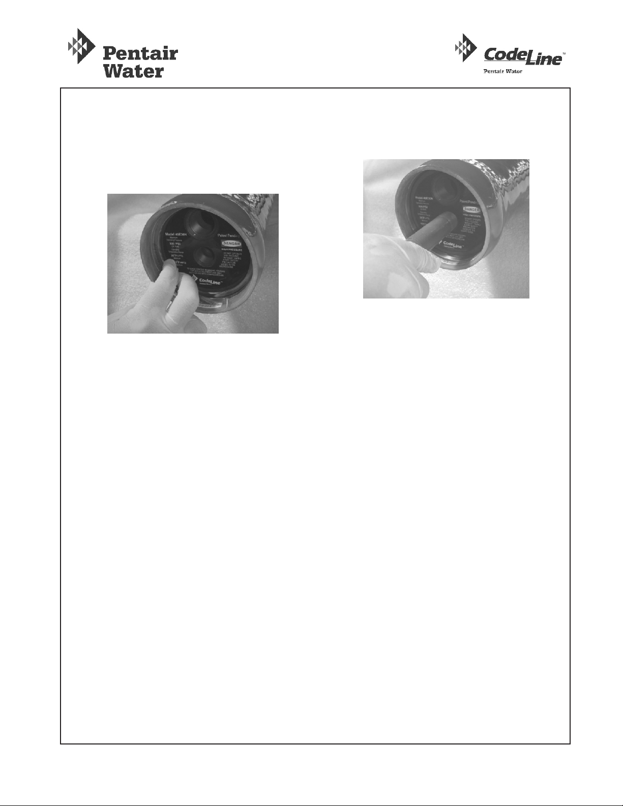
Do not...
service any component until you verify that
pressure is fully relieved from the vessel.
Do not...
use corroded components. Use of such
components may result in catastrophic
failure.
Do not...
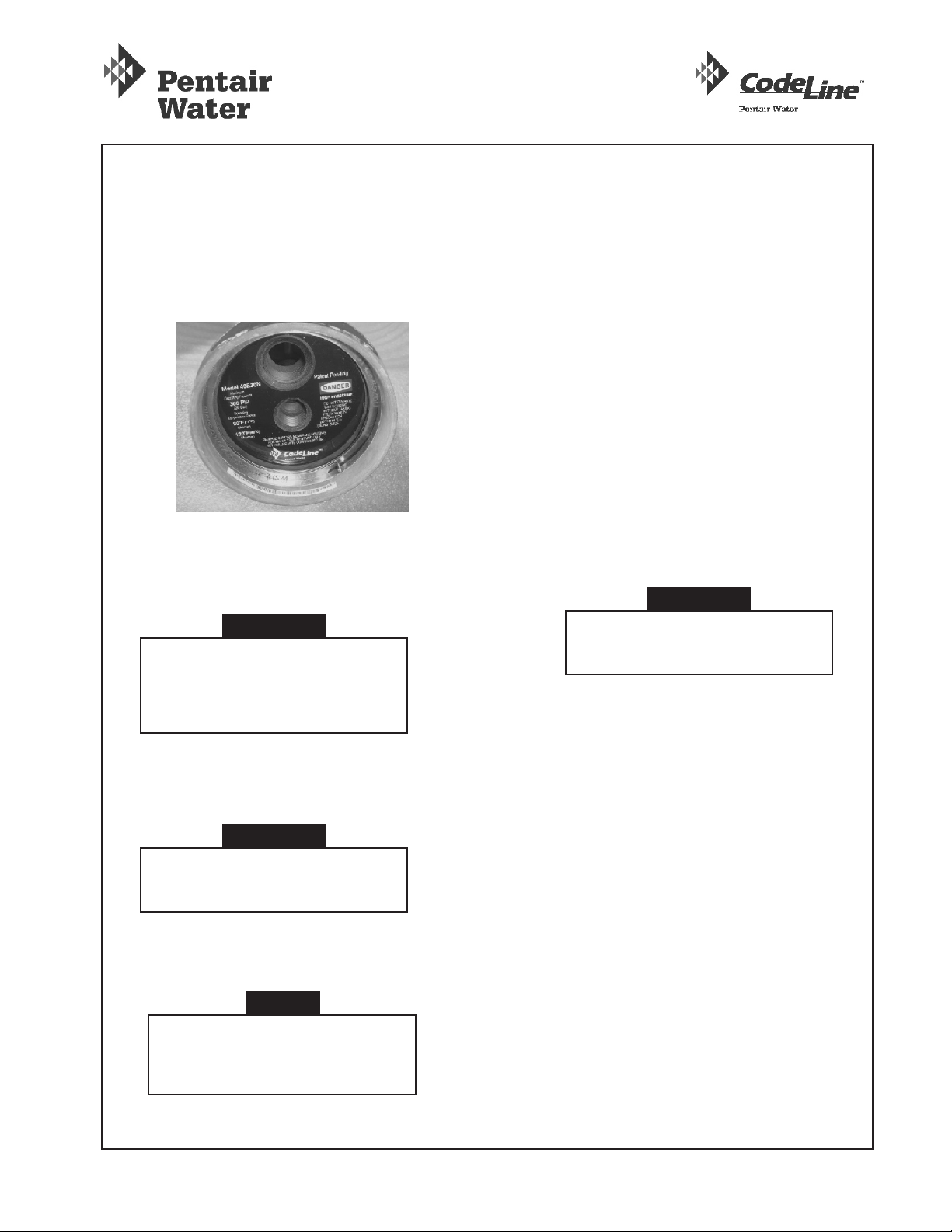
pressurize vessel until after visually inspecting
to ensure that the spiral retaining rings is
correctly installed and seated in their grooves.
Do not...
tolerate leaks or allow end closures to be
routinely wetted in any way.
Do not...
use excessive silicone lubricant.Do not...
pressurize vessel without element in place
unless permeate ports are plugged
internally.
Do not...
overtighten fittings in ports.Do not...
The 40E30N RO/UF Pressure Vessel is designed for
continuous, long-term use as a housing for reverse
osmosis and ultrafiltration elements in typical
commercial water treatment systems. Models are
available for 300 psi.
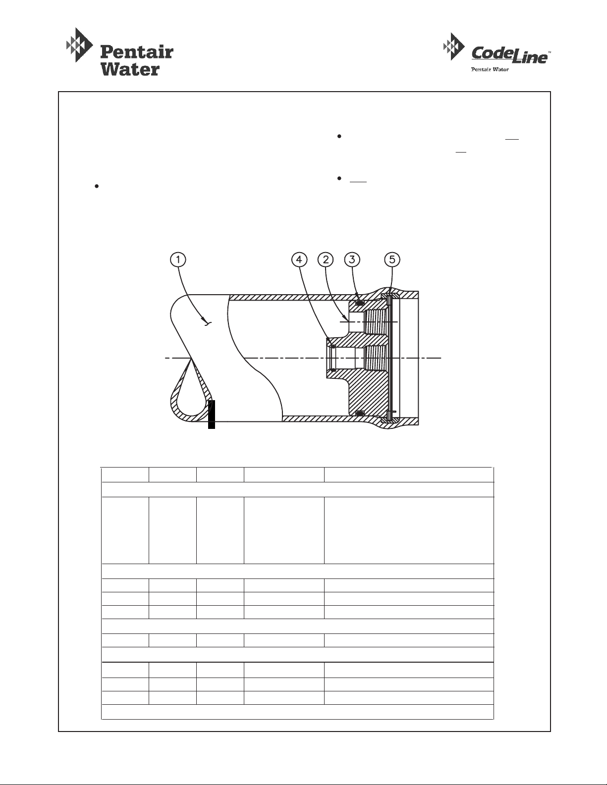
RO Pressure Vessel
The 40E Series vessels are designed to accommodate
any make of 4-inch nominal diameter spiral-wound
element with a 3/4” diameter male product water tube.
The fiberglass shell can be damaged by rigid clamping,
impact, scratches or abrasion. Metal parts must be
maintained free of corrosion to eliminate potentially
The information and guidelines incorporated in this
User’s Guide are intended only as a supplement to
good industrial practice. Full responsibility for correct
operation and maintenance of vessel remains with the
user.
This guide should be used in conjunction with drawing
number 518016.
When properly installed and maintained, Model 40E30N
vessels can be expected to provide safe operation over
a long service life.
40E30N Series User Guide Rev. B Updated 18/03/2011 Page 1 of 9
unsafe conditions due to corrosion.
Do not...
Use petroleum products on Noryl components.
Do not...
Allow petroleum or silicone based products to
come in contact with membrane elements during
installation or maintenance.
Use the vessel at negative pressureDo not...
Stand or climb on the pressure vessels, or theDo not...
feed / concentrate or permeate ports.

Page 2 of 9
Dwg Ref Qty Per Item # Description Materials
1 1 Shell Filament Wound epoxy/glass
composite. Head locking grooves
internally wound in place. Shell
exterior coated with white high gloss
polyurethane paint.
2 2 96288 End Plug PVC Thermoplastic
3 2 45317 Plug Seal Ethylene Polypropylene - O-ring
4 2 45296 Adapter Seal Ethylene Propylene O-ring
5 2 45260 Retaining Ring 316L SST
Shell
Head
Head Interlock
Figure 1: Section Through End Closure
Installation
Regardless of when or by whom your vessel may
have been installed, there are a few quick checks
you should make before use. Check that each
vessel is:
M o u n t e d w i t h c o m p l i a n t m a t e r i a l
(Polyurethane saddle) between the fiberglass
shell and any rigid frame.
Not used in any way to support other
components such as piping, manifolds
hanging from ports.
Free to expand under pressure - shell not
clamped rigidly in place, no rigid piping
connections to port fittings.
Vessel Support - Optional
6* 2 45058 Saddle Cast Urethane Elastomer
7* 2 47459 Strap Assembly 304 SST - Thermoplastic Cushion
8* 4 47458 Strap Screw 5/16 UNC, 18-8 Stainless Steel
* Not shown in above cross section

Opening the Vessel
WARNING
Relieve pressure from vessel
before beginning this procedure.
Contamination Removal
Metal oxidation products and mineral deposits can
interfere with vessel disassembly. Remove all
foreign matter from both ends of vessel as
follows:
Remove contaminants using a small wire brush
or suitable abrasive (such as medium-grade
TM
ScotchBrite ).
Flush away loosened deposits with clean water.
1.
2.
Removing the Head
40E30N head assembly is shown in Figure 1, page 2.
Remove head as follows:
Disconnect permeate piping as required at
nearest convenient joint, being careful not to
place undue stress on the threaded connections
of the plastic permeate port(s).
1.
CAUTION
DO NOT tap on fittings as this
could damage the ports.
Page 3 of 9
Cleaning inside the vessel
Disconnect Permeate Piping and the Feed Concentrate
Piping
Remove the Retaining Ring from the groove
1.
Lift the tabbed end of the retaining ring up and out
of the stainless steel groove in the shell and then
away from the head so that it rests in the end margin
of the vessel. This is best accomplished by using
TM
CodeLine Removal Tool, part number 50303, which
is available from your supplier. This can also be
accomplished using a screwdriver and a pair of pliers
if the tool is not readily available.
With the removal tool the retaining ring can be
lifted upward by simply rotating the tool
counterclockwise after inserting it over the tab on
the retaining ring (Use the smaller hole). Hold the
tool flat against the end margin and parallel to the
vessel bore. It is then possible to pull the end of the
retaining ring straight out. The retaining ring may
snap back into the groove if this alignment is not
closely adhered to. If the retaining ring is difficult
to remove, try soaking with a release agent such as
TM 0TM
LPS or WD4 , being careful to avoid any
contamination of a membrane element.
Retaining Ring Removal Tool
When using screwdriver and pliers, pry the tabbed
end of the retaining ring out of the stainless steel
groove with the tip of the screwdriver. Once the end
of the retaining ring is clear of the groove, grab the
tab with the pliers and pull towards the end of the
vessel until the end of the ring is resting in the end
margin of the shell.

Opening the Vessel...
Page 4 of 9
Remove the 4” retaining ring from the stainless steel
groove in the shell by rotating your finger behind the
ring as it continues to exit the groove.
2.
Removal of Retaining Ring
Once the retaining ring has been removed, examine
the area for burrs or dings which could damage the
TM
head or membrane. If necessary, use ScotchBrite
or 600 grade sandpaper to smooth the area.
3.
Removing Head Assembly
Using a mallet, tap the head assembly lightly. Do not
use a metal component to tap the head assembly.
1.
Thread a ½” O.D. Engineering Thermoplastic pipe
approximately 1 feet long into the permeate port.
2.
Carefully rock the head assembly back and forth to
release the seal (care should be taken to avoid too
much stress on the product port threads).
3.
Once the Plug seal is broken, pull straight outward to
remove the head assembly from the vessel.
4.
Remove and discard plug seal, taking care not
to scratch or otherwise damage the sealing
surfaces.
5.
Removing the head assembly
Repeat same procedure for opposite end of the
vessel.
6.
As soon as possible after removal, disassemble
and check all head components, as described in
Rebuilding the Head and Refurbishing Parts.
7.

Replacing Elements
The following procedures are provided for inform-
ation only. Elements should be installed in accord-
ance with the element manufacturer’s recommend-
ations. Where conflicts exist, contact the element
TM
manufacturer or CodeLine for clarification.
To replace elements, proceed as follows.
NOTE
Always remove and install element in
the direction of feed flow. The feed
end (upstream end) is the end plumbed
most directly to the pump.
Removing Elements
Remove heads from both ends of vessels as
described in Opening the Vessel.
Push element out of vessel from the upstream
end.
1.
2.
Inserting Elements
Page 5 of 9
For multi-element vessels, remove the intercon
-nectors and retain for reinstallation.
3.
Ensure that heads are available in clean, as-new
condition before proceeding. (If in doubt as to
head condition see section on inspecting parts,
).page 9
1.
CAUTION
When lubricating the vessel chamfer,
wear protective gloves or finger cots to
prevent cuts or penetration of
fiberglass.
Check that all required elements are ready for assem-
bly, with no dings or other damage which could
scratch the inside of the vessel.
2.
Check that the interior of the vessel is clean and free
o f b u r r s , s h a r p e d g e s o r o t h e r d a m a g e .
Remove any residual lubricant from the vessel bore
TM
and work a fresh, thin film of Parker-Super-O-Lube
silicon lubricant into the shell area behind the retaining
ring groove and approx. ½”into the vessel I.D. .
3.
Orient end plug port into desired position and
push plug fully into vessel. A sharp, forceful
thrust may be needed to enter plug seal into
the vessel bore.
4.
Installation of the End Plug Assembly
into the vessel
Carefully insert retaining ring into its groove.
This is done by inserting the lead end of the
spiral retaining ring (the non bent tab end) into
the retaining ring groove located in the shell,
and slowly pushing the remaining turns into
the shell.
5.
Inserting Retaining Ring into the groove

Closing the Vessel
Page 6 of 9
Check that the spiral retaining ring is fully seated
in the groove. If it is not, remove and check for
foreign material that is causing the spiral ring not
to sit into the groove.
6.
Insert each element with the brine seal (typically a
U-cup seat) installed on the upstream end with its
lip facing upstream.
8.
Install the interconnectors between multiple elements
as each succeeding element is installed.
9.
Push each element downstream into the shell as it is
installed until the element is fully engaged with the
downstream head. If the elements are hard to push,
make sure the brine seal is properly installed and you
are pushing from the upstream end. When all the
elements are fully inserted into the vessel, install the
upstream head as described in paragraphs 4 through
6 on page 5 & 6.
10.
CAUTION
System malfunctions and element damage
may result if elements are
installed in the wrong direction.
NOTE
On some systems it may be easier to install
the piping connections before the head
is installed.
If so, please proceed with Steps 10 & 11.
Retaining ring seated in the grooove
Reconnect piping to vessel as described in Remaking
Pipe Connection to Eng Plug on page 9.
11.
Pressurize the vessel. Inspect for leaks at connections
to the vessel and all around the vessel itself. If any
leaks occur, release pressure from the vessel and
tighten the fittings as necessary. Then pressurize
vessel and check for leaks again.
12.
CAUTION
DO NOT tolerate any leaks. Leaks can
result in corrosion and eventual
catastrophic vessel failure.
WARNING
Any remaining lubricant should be cleaned
from the vessel bore before applying fresh
lubricant. Glycerine is a commercially
available lubricant that will not foul the
membranes
Lubricate element seals sparingly with the element
manufacturers recommended lubricant or with
glycerine.
7.

Page 7 of 9
Head Disassembly
NOTE
Head Rebuilding should be performed in
a clean work area. Dust or dirt on O-rings
or other parts can scratch inner surfaces,
with subsequent leakage.
Using a small screwdriver or similar tool remove
the Plug Seal. However do not damage the sealing
surface in any way as it may lead to leakage.
1.
Removal of the Plug Seal
Using a small screwdriver or similar tool remove
the adapter Seal from the groove in the end plug.
2.
Removal of the Adapter Seal
Head Component Identification (40E30N) - Head Disassembled

Page 8 of 9
Head Assembly
Use only head components in as-new condition. Use
new O-rings each time the head is assembled.
1.
Lubricating Plug seals and O-rings
Cover O-rings with a this even layer of Parker Super
TM
O-Lube silicon lubricant or the lubricant recomm-
ended by your element supplier.
2.
NOTE
Glycerine is a commercially available
lubricant that will not foul elements.
However, silicon lubricant is
recommended for this application.
Assemble the Adapter Seal into the groove in the
End Plug.
3.
Inserting Adapter seal
Insert the Head Seal O-ring into the groove on the
outside diameter of the End Plug.
4.
Inserting Head seal
Protect heads from contamination until ready to
assemble into the vessel(s).
5.

Refurbishing Parts
Plastic parts: examine for cracking, softening or
discoloring. This may indicate chemical attack of the
material. Defective parts must be replaced. Alternate
material may be required. Contact your supplier or
TM
CodeLine for assistance.
Bearing/Sealing Plate and Permeate port:
cracked, discolored, sealing areas damaged
(chipped or gouged), port threads stripped or
cross-threaded.
Page 9 of 9
Remove any large deposits from metal parts
using a wire brush.
1.
Using a fine wire brush, remove any large
deposits from locking ring groove in the shell.
1.
TM
Using a medium or finer grade of ScotchBrite
and mild soap solution, clean the inside of the
vessel at least 4 inches in from each end. Take
care not to damage feed/concentrate port and its
respective seal.
2.
Use clean water to rinse away all loosened
deposits and soap residue.
3.
CAUTION
Use of components damaged by corrosion
can cause catastrophic failure.
Inspecting Parts
Metal parts: check for corrosion, scratches, dents,
cracks or other damages to insert ring and spiral
retaining ring.
Other parts: examine for any damage, such as
gouges, chips or cracks, that could affect structural
strength or sealing characteristics. The following are
some examples of defects that may require replace-
ment of the affected part.
Spiral Retaining rings: are the sole means of
end plug retention. Parts bent, corroded,
cracked or damaged in any way must not be
used. Carefully check for hairline cracks.
Refurbishing Shell
Examine inside of vessel for scratches, gouges,
or other imperfections that could prevent proper
sealing. If such areas exist and leaks are observed
when the vessel is placed back in service , the
shell may need to be replaced.
4.
Refurbishing Other Parts
Scrub the entire surface with medium grade
TM
ScotchBrite until all contaminants are removed.
2.
Rinse parts clean with fresh water and dry.3.
Inspect all parts for serviceability as specified
above.
4.
Replace all parts that cannot be restored to as-new
condition.
Part Replacement
Replace any parts showing signs of structural
damage or corrosion.
Seals should be replaced as necessary each time the
vessel is serviced. Any parts that need to be replaced
are ava ilabl e from yo ur suppl ier or from
TM
CodeLine .
Table of contents
Other Pentair Pool Products Water Heater manuals
Popular Water Heater manuals by other brands

Kenmore
Kenmore 153.318032 owner's manual

Quantum
Quantum Hot Spring Installation, user and service manual

A.O. Smith
A.O. Smith Innovo 12-160 Installation, service & maintenance manual

A.O. Smith
A.O. Smith ProMax SL Specification sheet

Pundmann
Pundmann THERM-9L Assembly, installation and operating instructions

Atmor
Atmor Platinum installation instructions