Pentair Pool Products MiniMax CH User manual

Rev. F 08-20-10 P/N 472128
1
1
FOR YOUR SAFETY - READ BEFORE OPERATING
Warning: If you do not follow these instructions exactly, a fire or explosion may result,
causing property damage, personal injury or loss of life.
For additional free copies of this manual; call (800) 831-7133.
Do not store or use gasoline or other flammable vapors and
liquids in the vicinity of this or other appliances.
For Your
Safety
Warning: Improper installation, adjustment, alteration, service or maintenance can
cause property damage, personal injury or death. Installation and service must be
performed by a qualified installer, service agency or the gas supplier.
MiniMax CH
POOL & SPA HEATERS
OPERATION & INSTALLATION MANUAL
WARNING
WHAT TO DO IF YOU SMELL GAS
• Do not try to light any appliance.
• Do not touch any electrical switch; do not use any phone in your building.
• Immediately call your gas supplier from a neighbor's phone.
Follow the gas supplier's instructions.
• If you cannot reach your gas supplier, call the fire department.
WARNING
Pentair Water Pool and Spa, Inc.
1620 Hawkins Ave., Sanford, NC 27330 •(800) 831-7133 or (919) 566-8000
10951 W. Los Angeles Ave., Moorpark, CA 93021 •(800) 831-7133 or (805) 553-5000
1
To
Consumer
Retain For
Future
Reference
®
FOR YOUR SAFETY - This product must be installed
and serviced by authorized personnel, qualified in
pool/spa heater installation. Improper installation
and/or operation can create carbon monoxide gas
and flue gases which can cause serious injury,
property damage, or death. For indoor installations,
as an additional measure of safety, Pentair Water
Pool and Spa, Inc. strongly recommends installation
of suitable Carbon Monoxide detectors in the vicinity
of this appliance and in any adjacent occupied
spaces. Improper installation and/or operation will
void the warranty.

P/N 472128 Rev. F 08-20-10
2
Customer Service
If you have questions about ordering Pentair Water Pool and Spa®replacement parts, and pool
products, please use the following contact information.
Customer Service and Technical Support, USA (8 A.M. to 4:30 P.M. Eastern/Pacific Times)
Phone: (800) 831-7133
Fax: (800) 284-4151
Sanford, North Carolina, USA (8 A.M. to 4:30 P.M. — Eastern Time)
Phone: (919) 566-8000
Fax: (919) 566-8920
Moorpark, California, USA (8 A.M. to 4:30 P.M. — Pacific Time)
Phone: (805) 553-5000
Fax: (805) 553-5515
Web site
visit www.pentairpool.com or www.staritepool.com to find information about Pentair products
© 2010 Pentair Water Pool and Spa, Inc. All rights reserved.
1620 Hawkins Ave., Sanford, NC 27330 – USA • (800) 831-7133 or (919) 566-8000
10951 West Los Angeles Ave., Moorpark, CA 93021 – USA • (800) 831-7133 or (805) 553-5000
This document is subject to change without notice.
Trademarks and Disclaimers: MiniMax®, Because reliability matters most®, Pentair Pool Products®and Pentair Water Pool and Spa®
are trademarks and/or registered trademarks of Pentair Water Pool and Spa, Inc. and/or its affiliated companies in the United States
and/or other counties. Unless noted, names and brands of others that may be used in this document are not used to indicate an
affiliation or endorsement between the proprietors of these names and brands and Pentair Water Pool and Spa, Inc. Those names
and brands may be the trademarks or registered trademarks of those parties or others.

Rev. F 08-20-10 P/N 472128
3
SAFETY INFORMATION
The MiniMax®CH pool heaters are designed and manufactured to provide many years of safe and reliable service when
installed, operated and maintained according to the information in this manual. Throughout the manual, safety warnings and
cautions are identified by the “ “ symbol. Be sure to read and comply with all of the warnings and cautions.
DANGER — CARBON MONOXIDE GAS IS DEADLY
• • READ OWNERS MANUAL COMPLETELY BEFORE OPERATING. • •
THIS PRODUCT MUST BE INSTALLED AND SERVICED BY A PROFESSIONAL SERVICE
TECHNICIAN, QUALIFIED IN POOL HEATER INSTALLATION. Some jurisdictions require that
installers be licensed. Check with your local building authority about contractor licensing requirements.
Improper installation and/or operation could create carbon monoxide gas and flue gases which could cause
serious injury or death. Improper installation and/or operation will void the warranty.
Exhaust from this pool heater contains toxic levels of carbon monoxide, a dangerous, poisonous gas
you cannot see or smell. Symptoms of carbon monoxide exposure or poisoning include dizziness,
headache, nausea, weakness, sleepiness, muscular twitching, vomiting and inability to think clearly.
IF YOU EXPERIENCE ANY OF THE ABOVE SYMPTOMS, IMMEDIATELY TURN OFF THE POOL
HEATER,LEAVETHEVICINITYOFTHEPOOLORSPAANDGETINTOFRESHAIRIMMEDIATELY.
THE POOL HEATER MUST BE THOROUGHLY TESTED BY A GAS PROFESSIONAL BEFORE
RESUMING OPERATION.
EXCESSIVE CARBON MONOXIDE EXPOSURE CAN CAUSE BRAIN DAMAGE OR DEATH.
NEVER use this pool heater indoors without specified ventilation system (and properly installed vent pipe).
NEVER use this pool heater in the home or in partly enclosed areas (such as garages), unless the
specified ventilation system is used. If used outdoors, install far from open windows, doors, vents
and other openings.
Pentair strongly recommends that all vents, pipes and exhaust systems be initially and periodically
tested for proper operation. This testing can be accomplished by using a hand-held carbon monoxide
meter and/or by consulting with a gas professional.
Pool heaters must be used in conjunction with carbon monoxide detectors installed near the pool heater.
The carbon monoxide detectors must be periodically inspected for proper operation so as to insure
continued safety. Broken or malfunctioning carbon monoxide detectors must be replaced immediately.
WARNING — Risk of fire or explosion from incorrect fuel use or faulty fuel conversion. Do not try to run a
heater set up for natural gas on propane gas or vice versa. Only qualified service technicians should
attempt to convert heater from one fuel to the other. Do not attempt to alter the rated input or type of
gas by changing the orifice. If it is necessary to convert to a different type of gas, consult your Pentair
dealer. Serious malfunction of the burner can occur which may result in loss of life. Any additions,
changes, or conversions required in order for the appliance to satisfactorily meet the application
needs must be made by a Pentair dealer or other qualified agency using factory specified and approved
parts. The heater is available for use with natural gas or LP (propane) gas only. It is not designed to
operate with any other fuels. Refer to the nameplate for the type of gas the heater is equipped to use.
• Use heater only with the fuel for which it is designed.
• If a fuel conversion is necessary, refer this work to a qualified service technician or gas supplier
before putting the heater into operation.
WARNING — Risk of fire or explosion from flammable vapors. Do not store gasoline, cleaning fluids, varnishes,
paints, or other volatile flammable liquids near heater.
WARNING — Risk of explosion if unit is installed near propane gas storage. Propane (LP) gas is heavier than
air. Consult local codes and fire protection authorities about specific installation requirements and
restrictions. Locate the heater away from propane gas storage and filling equipment as specified by
the Standard for the Storage and Handling of Liquefied Petroleum Gases, CAN/CSA B149.2 (latest
edition) or ANSI/NFPA 58 (latest edition).

P/N 472128 Rev. F 08-20-10
4
SAFETY INFORMATION, (cont’d.)
WARNING — Risk of fire. Do not place articles on, near or against the heater.
WARNING — Risk of burn hazard. To reduce the risk of injury, do not touch the top heater vent cover when the
heater is operating. Top heater vent covers are HOT and can burn when touched causing linjury. Do
not allow children to play on or around heater or associated equipment.
WARNING — Risk of asphyxiation if exhaust is not correctly vented. Follow venting instructions exactly when
installing heater.
CONSUMER INFORMATION AND SAFETY
WARNING
The U.S. Consumer Product Safety Commission warns that carbon monoxide is an "invisible killer". Carbon
monoxide is a colorless and odorless gas.
1. Carbon monoxide is produced by burning fuel, including natural gas and propane.
2. Proper installation, operation and maintenance of fuel-burning appliances in the home is the most important
factor in reducing carbon monoxide poisoning.
3. Be sure that fuel burning appliances such as heaters are installed by professionals according to manufacturer's
instructions and codes.
4. Always follow the manufacturer's directions for safe operation.
5. Have the heating system (including vents) inspected and serviced annually by a trained service technician.
6. Examine vents regularly for improper connections, visible cracks, rust or stains.
7. Install battery-operated carbon monoxide alarms. The alarms should be certified to the requirements of the
most recent UL, IAS, CSA and IAPMO standard for carbon monoxide alarms. Test carbon monoxide alarms
regularly and replace dead batteries.
GENERAL SPECIFICATIONS
NOTICE:
• Combustion air contaminated by corrosive chemical fumes can damage the heater and will void the warranty.
• The Combination Gas Control Valve on this heater differs from most appliance gas controls. If it must be replaced,
for safety reasons replace it only with an identical gas control.
• The heater is designed for the heating of chlorine, bromine or salt system swimming pools and spas. It should NOT be
used as a space heating boiler, or general purpose water heater.
• The heater should be located in an area where leakage of the heater or connections will not result in damage to the
area adjacent to the heater or to the structure. When such locations cannot be avoided, it is recommended that a suitable
drain pan, adequately drained, be installed under the heater. The pan must not restrict air flow.
• The heater may not be installed within 5 ft. (1.5M ) of the inside surface of a pool or spa unless it is separated by a solid
fence, wall or other permanent barrier.

Rev. F 08-20-10 P/N 472128
5
Table of Contents
Safety Information ..................................................................................................... 3
Consumer Information and Safety ........................................................................... 4
General Specifications .............................................................................................. 4
Introduction ................................................................................................................ 6
Important Notices .............................................................................................................................................................. 6
Warranty Information ......................................................................................................................................................... 7
Operation .................................................................................................................... 7
Safety Rules ...................................................................................................................................................................... 7
Millivolt Lighting/Operation - Natural & Propane ................................................................................................................ 8
Operating (Controls) .......................................................................................................................................................... 9
Maintenance ............................................................................................................... 10
Maintenance Instructions ................................................................................................................................................... 10
Relief Valve ........................................................................................................................................................................ 10
Energy Saving Tips ............................................................................................................................................................ 10
Spring and Fall Operation .................................................................................................................................................. 10
Winter Operation ............................................................................................................................................................... 10
Chemical Balance .............................................................................................................................................................. 11
Installation Instructions ............................................................................................ 12
Specifications ....................................................................................................................... 12
Plumbing Connections ......................................................................................................... 13
Plumbing/Valves ................................................................................................................................................................ 13
Manual Bypass .................................................................................................................................................................. 13
Below Pool Installation ....................................................................................................................................................... 13
Water Connections ...............................................................................................................14
Reverse Water Connections .............................................................................................................................................. 14
Insulating High Limits when Reversing Heads ................................................................................................................... 14
Gas Connections .................................................................................................................. 15
Gas Line Installation .......................................................................................................................................................... 15
Pipe Sizing Chart/Gas Pressure Requirements ................................................................................................................. 15
Pipe Sizing Chart/Propane 2 Stage Regulation ................................................................................................................. 16
Regulated Manifold Pressure Test ..................................................................................................................................... 16
Gas Pressure Requirements ............................................................................................................................................. 16
Ventilation .............................................................................................................................. 17
Outdoor Installation Requirements .................................................................................................................................... 17
Outdoor Vent Cap Installation ............................................................................................................................................ 17
Indoor/Outdoor Venting–General Requirements ................................................................................................................ 18
Indoor Installation Requirements ....................................................................................................................................... 19
Installation on Floors Constructed of Combustible Materials ............................................................................................. 20
Indoor Draft Hood Installation ............................................................................................................................................ 20
Electrical ................................................................................................................................ 21
Millivolt Wiring Diagram ..................................................................................................................................................... 21
Troublshooting (General) .......................................................................................... 22
MiniMax®CH Parts List & Exploded View ................................................................ 23-25

P/N 472128 Rev. F 08-20-10
6
MiniMax®CH
Pool and Spa Heaters
Congratulations on your purchase of a MiniMax®CH high performance heating system. Proper installation
and service of your new heating system and correct chemical maintenance of the water will ensure years of
enjoyment. The MiniMax®CH is a compact, lightweight and efficient gas fired high performance pool and spa
heater that can be directly connected to schedule 40 PVC pipe and has a built-in top. The MiniMax®CH is a
millivolt heater and has a self sustaining pilot and requires NO external power source.
IMPORTANT NOTICES
THIS PRODUCT MUST ONLY BE INSTALLED AND SERVICED BY A PROFESSIONAL SERVICE TECHNICIAN
QUALIFIED IN POOL HEATER INSTALLATION.
...For the installer and operator of the MiniMax®CH pool and spa heater. The manufacturer’s warranty may be
void if, for any reason, the heater is improperly installed and/or operated. Be sure to follow the instructions set
forth in this manual. If you need any more information, or if you have any questions regarding to this pool
heater, please contact Pentair Water Pool and Spa, Inc. at (800) 831-7133.
These heaters are designed for the heating of chlorine, bromine or salt system swimming pools and spas
or in non-stationary installations, and should never be employed for use as space heating boilers or
general purpose water heaters. The manufacturer’s warranty may be void if, for any reason, the heater
is improperly installed and/or operated. Be sure to follow the instructions set forth in this manual.
CAUTION
OPERATING THIS HEATER CONTINUOUSLY AT WATER TEMPERATURE BELOW 68° F. WILL CAUSE HARMFUL
CONDENSATION AND WILL DAMAGE THE HEATER AND WILL VOID THE WARRANTY.
Do not use the heater to protect pools or spas from freezing if the final maintenance temperature desired is
below 68° F. as this will cause condensation related problems.
CODE REQUIREMENTS
The installation must conform with local codes or in the absence of local codes with the latest National Fuel
Gas Code, ANSI Z223.1, and the latest edition of the National Electrical Code, NFPA 70.
Installation in Canada to be made in accordance with the latest CAN/CGA-B149.1 or .2 and CSA C22.1
Canadian Electric Code, part 1.
DANGER
CARBON MONOXIDE GAS IS DEADLY – Exhaust from this pool heater contains toxic levels of carbon monoxide, a
dangerous, poisonous gas you cannot see or smell.
Introduction

Rev. F 08-20-10 P/N 472128
7
Operation
This instruction manual provides operating instructions,
installation and service information for the MiniMax®CH high
performance heater. The information in this manual applies to
the MiniMax®CH 150, 200, 250, 300, 350, and 400 natural gas
and propane (LP) models.
It is very important that the owner/installer read and understand
the section covering installation instructions, and recognize the
local and state codes before installing the MiniMax®CH. History
and experience has shown that most heater damage is caused by
improper installation practices.
WARRANTY INFORMATION
The MiniMax®CH pool heater is sold with a limited factory
warranty. Specific details are described on the warranty
registration card which is included with the product.Return
the warranty registration card after filling in the serial number
from the rating plate inside the heater.
Pentair Water Pool and Spa’s high standards of excellence
include a policy of continuous product improvement resulting in
your state-of-the-art heater. We reserve the right to make
improvements which change the specifications of the heater
without incurring an obligation to update the current heater
equipment.
SAFETY RULES
1. Spa or hot tub water temperatures should never exceed
104° F (40° C). A temperature of 100° F (38° C) is
considered safe for a healthy adult. Special caution is
suggested for young children.
2. Drinking of alcoholic beverages before or during spa or hot
tub use can cause drowsiness which could lead to
unconsciousness and subsequently result in drowning.
3. Pregnant women beware! Soaking in water above 102° F
(39° C) can cause fetal damage during the first three months
of pregnancy (resulting in the birth of a brain-damaged or
deformed child). Pregnant women should stick to the
100° F (38° C) maximum rule.
4. Before entering the spa or hot tub, the user should check the
water temperature with an accurate thermometer. Spa or
hot tub thermostats may err in regulating water temperatures
by as much as 4° F (2.2° C).
5. Persons with a medical history of heart disease, circulatory
problems, diabetes or blood pressure problems should obtain
their physician's advice before using spas or hot tubs.
6. Persons taking medication which induce drowsiness, such
as tranquilizers, antihistamines or anticoagulants should not
use spas or hot tubs.
Should overheating occur or the gas supply fail to shut off, turn off the manual gas control valve to the
appliance. Do not use this heater if any part has been under water. Immediately call a qualified service
technician to inspect the heater and to replace any part of control system and gas control which has been
under water.
WARNING
Introduction (contd.)
PRODUCT IDENTIFICATION
To identify the heater, see rating plate on the inner front panel of the
heater. There are two designators for each heater, one is the Model
Number and the other is the Heater Identification Number (HIN).
a. Model Number:
Example: 400
1st through 3rd character indicated: Input rating (Btu/hr) X 1000
b. Heater Identification Number (HIN):
The following example simplifies the identification system.
123456
RTH004HCknalBMNknalB
1) HTR : Heater
2) (150, 200, 250, 300, 400) : Input rating (Btu/hr) X 1000
3) CH : MiniMax®CH
4) Blank : Standard Model
5) N M : Gas type (Natural gas) & Ignition Device
6) Options :
Blank: Standard Model
ASME: ASME Certified (Bronze Headers)
ASHI: ASME Certified Bronze Header & High Altitude Rating
HALT: High Altitude Rating
CAN: Canadian Compliance
CANH: Canadian Compliance and High Altitude

P/N 472128 Rev. F 08-20-10
8
Operation (contd.)
FOR YOUR SAFETY: READ BEFORE LIGHTING
A. This heater is equipped with a pilot which must be
lighted manually. When lighting the pilot, follow
these instructions exactly.
B. BEFORE LIGHTING smell all around the heater
area for gas. Be sure to smell next to the floor because
some gas is heavier than air and will settle on the
floor.
WHAT TO DO IF YOU SMELL GAS
- Do not try to light any heater.
- Do not touch any electrical switch; do not use any
phone in your building.
- Immediately call your gas supplier from a neighbor's
phone. Follow the gas supplier's instructions.
- If you cannot reach your gas supplier, call the Fire
Department.
C. Use only your hand to push in or turn the gas control
knob. Never use tools. If the knob will not push in or
turn by hand, don't try to repair it. Call a qualified
service technician. Forced or attempted repair may
result in a fire or explosion.
D. Do not use this heater if any part has been under water.
Immediately call a qualified service technician to
inspect the heater and to replace any part of the control
system and any gas control which has been under water.
MINIMAX®CH MILLIVOLT LIGHTING/OPERATION-NATURAL GAS & PROPANE
1. STOP! Read the safety information above.
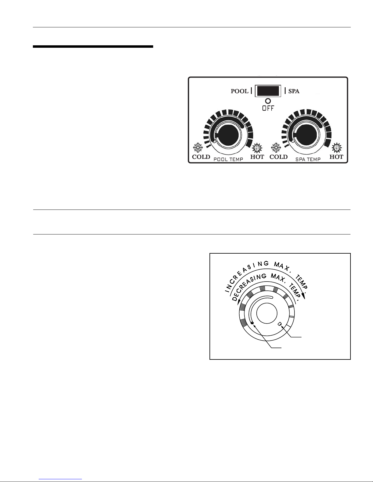
2. Set the thermostat to the lowest setting.
3. Turn off electric power to the heater.
4. Push in gas control knob slightly and turn clock-
wise to “OFF”.
Gas control knobs shown in “OFF” position.
NOTE
Knob cannot be turned from “Pilot to “OFF”” unless
knob is pushed in slightly. DO NOT FORCE.
5. Wait five (5) minutes to clear out any gas. If you then
smell gas, STOP! Follow "B" in the safety informa-
tion above. If you don't smell gas, go to the next step.
6. Push in gas control knob slightly and turn
counterclockwise to “Pilot”.
If you do not follow these instructions exactly, a fire or explosion may result causing personal injury, loss of life
and property damage.
Since propane gas is heavier than air, escaping propane will accumulate and remain at ground level. Do not
attempt to light the heater. If you suspect a propane leak, lighting the heater can result in a fire or explosion
which can cause personal injury, death, and property damage.
WARNING
7. Push the control knob all the way and hold in.
Immediately light the pilot with Presslite
matchless ignition system by pressing the red
igniter button (located at the panel next to the gas
valve). Continue to hold the control knob in for
about one (1) minute after the pilot is lit. Release
knob and it will pop back up. Pilot should remain
lit. If it goes out, repeat steps 4 through 7.
• If knob does not pop up when released, stop and
immediately call your service technician or gas
supplier.
• If the pilot will not stay lit
after several tries, turn the
gas control knob to “OFF”
and call your service
technician or gas supplier.
8. Turn knob on gas control
counterclockwise to
“ON”.
9. Replace the control access
door.
10. Set the thermostat to the
desired setting.
LIGHTING INSTRUCTIONS
TO TURN OFF GAS TO HEATER
1. Set the thermostat to lowest setting.
2. Turn off all electric power to the heater if service is
to be performed.
3. Remove control access door.
4. Push in gas control knob slightly and turn clockwise
to "OFF". Do not force.
5. Replace control access door.
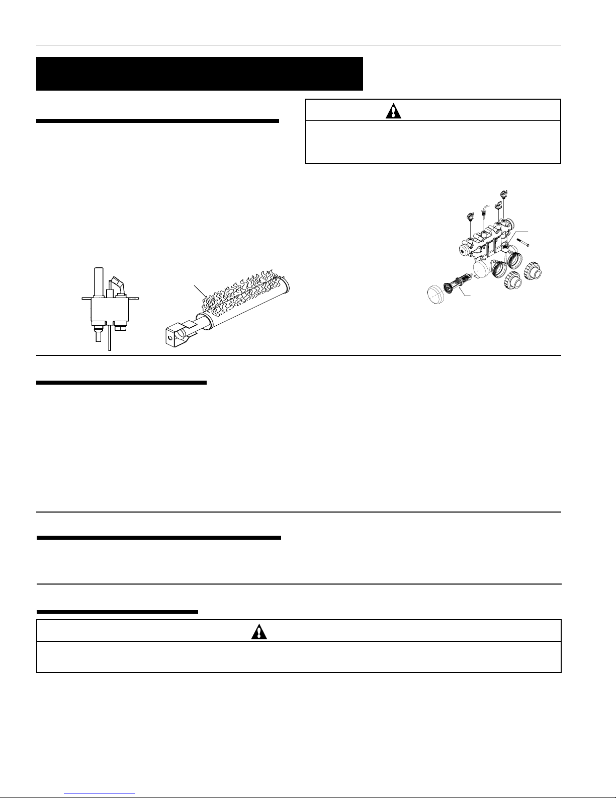
Robertshaw Millivolt Gas Valve Honeywell Millivolt Gas Valve
Figure 1. Figure 2.
Figure 3.
Figure 4. Pilot

Rev. F 08-20-10 P/N 472128
9
Knob Stopper
Screw A
OPERATING (CONTROLS)
Dual Temperature Control System
Operation (contd.)
For convenience and economy all MiniMax®CH
heaters are equipped with two thermostats on the
front of the heater control panel; see Figure 5.
THERMOSTAT KNOB STOPPER
Each thermostat is equipped with a mechanical
stop that can be locked or unlocked with use of a
screwdriver to prevent temperatures in excess of
that desired by the user; see Figure 6.
The maximum setting can be adjusted by
loosening the screw "A" and turning the stopper
dial to desired maximum setting. Lock the setting
by tightening the screw. The Mechanical stop is
under the knob. Ensure that the knob is stopping at the correct position when the knob is rotated clockwise
from a lower temperature position. (See Thermostat Adjustment.)
NOTE
To eliminate error due to piping heat losses, measure pool temperature with an accurate
thermometer directly at the pool or spa.
THERMOSTAT ADJUSTMENT
The knob with locking feature eliminates the need for
constant thermostat adjustments. Set the knob pointer to
the desired pool or spa temperature.
If further adjustment is needed, rotate the knob until the
desired temperature is obtained. This knob position
corresponding to your desired maximum pool or spa
temperature may now be preset (locked) by the knob
stopper which prevents the knob from being turned
beyond the maximum temperature you set.
POWER (THERMOSTAT SELECT) SWITCH
The Pool/Off/Spa switch allows the heater to be turned
off when heating is not desired.
1. “Pool” position - Maintains selected pool temperature.
2. “Off” position - Heater will not come on regardless of drop in pool or spa temperature.
3. “Spa” position - This allows separate control of spa water temperature or an alternate lower pool
temperature.
Figure 5.
Figure 6.

P/N 472128 Rev. F 08-20-10
10
MAINTENANCE INSTRUCTIONS
It is recommended that you check the following items at least
every six months and at the beginning of every swimming
season.
1. Examine the venting system. Make sure there are no ob-
structions in the flow of combustion and ventilation air.
2. Visually inspect the main burner and the pilot burner
flame. The normal color of the flame is blue. When flame
appears yellow, burners should be inspected and cleaned;
see Figure 8.
3. Keep the heater area clear and free from combustibles
and flammable liquids.
Maintenance
Pressure Relief Valve
In some installations, a
pressure relief valve
(PRV) is required on the
MiniMax®CH heater. To
install a PRV, carefully
drill a 3/8 in. hole in
center of 3/4 in. NPT
port (on main header)
being careful to drill
only thru wall at bottom
of 3/4 in. NPT port and
no deeper—now thread
in the 3/4 NPT PRV. (Sold separately.)
ENERGY SAVING TIPS
1. If possible, keep pool or spa covered when not in use.
This will not only cut heating costs, but also keep dirt and
debris from settling in the pool and conserve chemicals.
2. Reduce the pool thermostat setting to 78° F. or lower.
This is accepted as being the most healthy temperature
for swimming by the American Red Cross.
3. Use an accurate thermometer.
4. When the proper maximum thermostat settings have been
determined, tighten the thermostat knob stopper.
5. Set time clock to start circulation system no earlier than
daybreak. The swimming pool loses less heat at this time.
6. For pools that are only used on the weekends, it is not
necessary to leave the thermostat set at 78° F. Lower the
temperature to a range that can be achieved easily in one
day. Generally, this would be 10° F. to 15° F., if pool
heater is sized properly.
7. During the winter or while on vacation, turn the heater off.
8. Set up a regular program of preventative maintenance
for the heater each new swimming season. Check heat
exchanger, controls, burners, operation, etc.
SPRING AND FALL OPERATION
If the pool is being used occasionally, do not turn the heater completely off. Set the thermostat down to 65° F. This will
keep the pool and the surrounding ground warm enough to bring the pool up to a comfortable swimming temperature in a
shorter period of time.
CAUTION
OPERATING THIS HEATER CONTINUOUSLY AT WATER TEMPERATURE BELOW 68° F. WILL CAUSE HARMFUL
CONDENSATION AND WILL DAMAGE THE HEATER AND WILL VOID THE WARRANTY.
If the pool won't be used for a month or more, turn the heater off at the main gas valve. For areas where there is no danger of
water freezing, water should circulate through the heater all year long, even though you are not heating your swimming pool.
The MiniMax®CH should not be operated out doors at temperatures below 0° F. for propane and -20° F. for natural gas.
Where freezing is possible, it is necessary to drain the water from the heater. This may be done by opening the drain valve
located at the inlet/outlet header (see Figure 9.) allowing all water to drain out of the heater. It would be a good practice to use
compressed air to blow the water out of the heat exchanger. (See additional notes under Important Notices in Introduction
on page 3.)
WINTER OPERATION
Figure 8.
Blue Flame
Figure 7.
FOR PRV
INSTALLATION
DRILL THRU
THE NPT PORT
REMOVE FLOW VALVE
BEFORE DRILLING
THE NPT PORT
Figure 9.
CAUTION
REMOVE THE FLOW VALVE ASSEMBLY WHEN DRILLING
THE HOLE TO INSTALL A PRV. OTHERWISE, YOU WILL
DRILL INTO THE VALVE ASSEMBLY.

Rev. F 08-20-10 P/N 472128
11
CHEMICAL BALANCE
Pool and Spa Water
Your Pentair Water Pool and Spa®pool heater was designed
specifically for your spa or pool and will give you many
years of trouble free service provided you keep your water
chemistry in proper condition.
Three major items that can cause problems with your pool
heater are improper pH, disinfectant residual, and total
alkalinity. These items, if not kept properly balanced, can
shorten the life of the heater and cause permanent damage.
WHAT A DISINFECTANT DOES
Two pool guests you do not want are algae and bacteria.
To get rid of them and make pool water sanitary for
swimming - as well as to improve the water's taste, odor
and clarity - some sort of disinfectant must be used.
Chlorine and bromine are universally approved by health
authorities and are accepted disinfecting agents for bacteria
control.
WHAT IS A DISINFECTANT RESIDUAL?
When you add chlorine or bromine to the pool water, a
portion of the disinfectant will be consumed in the process
of destroying bacteria, algae and other oxidizable materials.
The disinfectant remaining is called chlorine residual or
bromine residual. You can determine the disinfectant
residual of your pool water with a reliable test kit, available
from your local pool supply store.
You must maintain a disinfectant residual level adequate
enough to assure a continuous kill of bacteria or virus
introduced into pool water by swimmers, through the air,
from dust, rain or other sources.
It is wise to test pool water regularly. Never allow chlorine
residual to drop below 0.6 ppm (parts per million). The
minimum level for effective chlorine or bromine residual
is 1.4 ppm.
pH - The term pH refers to the acid/alkaline balance of
water expressed on a numerical scale from 0 to 14. A test
kit for measuring pH balance of your pool water is available
from your local pool supply store; see Table 1.
Maintenance (contd.)
RULE: 7.4 to 7.6 is a desirable pH range. It is essential to
maintain correct pH, see Table 2.
If pH becomes too high (over alkaline), it has
these effects:
1. Greatly lowers the ability of chlorine to destroy bacteria
and algae.
2. Water becomes cloudy.
3. There is more danger of scale formation on the plaster
or in the heat exchanger.
4. Filter elements may become blocked.
If pH is too low (over acid) the following
conditions may occur:
1. Excessive eye burn or skin irritation.
2. Etching of the plaster.
3. Corrosion of metal fixtures in the filtration and
recirculation system, which may create brown, blue,
green, or sometimes almost black stains on the plaster.
4. Corrosion of copper in the heater, which may cause
leaks.
5. If you have a sand and gravel filter, the alum used as a
filter aid may dissolve and pass through the filter.
CAUTION: Do not test for pH when the chlorine
residual is 3.0 ppm or higher, or bromine residual is
6.0 ppm or higher. See your local pool supply store
for help in properly balancing your water chemistry.
RULE: Chemicals that are acid lower pH. Chemicals
that are alkaline raise pH.
Heat exchanger damage resulting from chemical
imbalance is not covered by the warranty.
CAUTION
Muriatic Acid has a pH of about 0. Pure water is 7 (neutral).
Weak Lye solution have a pH of 13-14.
pH Chart
Table 1.
Strongly Acid Neutral Strongly Alkaline
0 1 2 3 4 5 6 7 8 9 10 11 12 13 14
ALKALINITY High - Low:
"Total alkalinity" is a measurement of the total amount
of alkaline chemicals in the water, and control pH to a
great degree. (It is not the same as pH which refers
merely to the relative alkalinity/acidity balance.) Your
pool water's total alkalinity should be 100 - 140 ppm
to permit easier pH control.
A total alkalinity test is simple to perform with a
reliable test kit. You will need to test about once a
week and make proper adjustments until alkalinity is
in the proper range. Then, test only once every month
or so to be sure it is being maintained. See your local
pool dealer for help in properly balancing the water
chemistry.
7.2
6.8 7.0 7.4 7.6 7.8 8.0 8.2 8.4
Add Soda, Ash or
Sodium Bicarbonate
Add AcidMarginalIdealMarginal
pH Control Chart
Table 2.

P/N 472128 Rev. F 08-20-10
12
Installation Instructions
IMPORTANT NOTICE: These installation instructions are designed for use by qualified personnel only,
trained especially for installation of this type of heating equipment and related components. Some states require
installation and repair by licensed personnel. If this applies in your state, be sure your contractor bears the
appropriate license.
SPECIFICATIONS
ledoMmiD"A"miD"B"
051.ni8/771.ni½6
002.ni8/702.ni½9
052.ni8/732.ni½21
003.ni8/762.ni½51
053.ni8/792.ni½81
004.ni8/333.ni8/322
ledoMmiD"A"miD"B"miD"C"miD"D"
051.ni8/771.ni½6.ni¾7.ni¾93
002.ni8/702.ni½9.ni01.ni¾24
052.ni8/732.ni½21.ni01.ni¾24
003.ni8/762.ni½51.ni¼01.ni¾34
053.ni8/792.ni½81.ni31.ni¾74
004.ni8/333.ni8/322.ni71.ni¾15
ledoMmiD"A"miD"B"miD"C"miD"D"miD"E"
051.ni8/771.ni½6.ni31.ni¾25.ni6
002.ni8/702.ni½9.ni31.ni8/735.ni7
052.ni8/732.ni½21.ni31.ni8/735.ni7
003.ni8/762.ni½51.ni31.ni55.ni8
053.ni8/792.ni½81.ni31.ni65.ni9
004.ni8/333.ni8/322.ni71.ni¾06.ni01
Outdoor installation - stackless
Indoor installation - stack (USA only)
Outdoor shelter installation (Canada)
Outdoor installation - with vent kit
Table 3.
Table 4.
Table 5.
FRONT VIEW SIDE VIEW
"D"
DIM
"C"
DIM.
5
4.875
"A" DIM.
"B" DIM.
"E" DIM.
211
2
1
2
28
137
8
107
8
GAS LINE
OPENING
®
HIGHPERFORMANCE HEATER
CH
28"
"D"
DIM
"A" DIM.
5
4.875
"B" DIM.
"E" DIM.
"C"
DIM.
2
1
21
2
1
®
HIGHPERFORMANCE HEATER
CH
®
211
2
137
8
1
2"A" DIM.
"B" DIM.
32
5
4.875
HIGH PERFORMANCE HEATER
CH

Rev. F 08-20-10 P/N 472128
13
PUMP
FILTER
POOL
HEATER
CHECK
VALVE
MANUAL
BY-PASS ISOLATION
VALVE
ISOLATION
VALVE
TO
POOL
CHECK
VALVE
FROM
POOL
2
1
3
SPATEMP
HOT
POOLTEMP
COLD
OFF
SPA
POOL
THERMOSTATSELECT
HOT
COLD
Installation (contd.)
Figure 10.
Optional.
Required when installation is below water level.
Required when flow rates exceed 120 gpm.
3
1
2
PLUMBING CONNECTIONS
The MiniMax®CH heater has the unique capability of
direct schedule 40 PVC plumbing connections.
CAUTION
Before operating the heater on a new installation,
turn on the circulation pump and bleed all the air
from the filter using the air relief valve on top of the
filter. Water should flow freely through the heater.
Do not operate the heater unless water in the pool/
spa is at the proper level.
PLUMBING
VALVES
When any equipment is located below the surface
of the pool or spa, valves should be placed in the
circulation piping system to isolate the equipment
from the pool or spa.
Check valves are recommended to prevent back
siphon.
CAUTION
Exercise care when installing chemical feeders so
as to not allow back siphoning of chemical into the
heater, filters or pump. When chemical feeders are
installed in the circulation of the piping system,
make sure the feeder outlet line is down stream of
the heater, and is equipped with a positive seal
non-corrosive “Check Valve”, (P/N R172288),
between the feeder and heater.
ledoM.niM*.xaM
05102021
00202021
05203021
00303021
05304021
00404021
dednemmocermumixamehtdeecxetonoD*
.gnipipgnitcennocehtrofetarwolf
Table 6.
MANUAL BY-PASS
Where the flow rate exceeds the maximum 120
GPM, a manual bypass should be installed and
adjusted. After adjustments are made, the valve
handle should be removed to avoid tampering.
BELOW POOL INSTALLATION
If the heater is below water level, the pressure
switch should be adjusted. This adjustment must
be done by a qualified service technician.
See following CAUTION.
CAUTION
BELOW OR ABOVE POOL INSTALLATION
The water pressure switch is set in the factory at 1½
PSI. This setting is for a heater installed at pool level or
within 3’ above or 3’ below. If the heater is to be installed
more that 3’ above or 3’ below, the water pressure switch
must be adjusted by a qualified service technician.
FLOW SWITCH
If the heater is installed more the 6’ above the pool or
more than 10’ below the pool level, you will be beyond
the limits of the pressure switch and a flow switch must
be installed. Locate and install the flow switch externally
on the outlet piping from the heater, as close as possible
to the heater. Connect the flow switch wires in place of
the water pressure switch wires.

P/N 472128 Rev. F 08-20-10
14
WATER CONNECTIONS
Reversible Inlet/Outlet Connection
The MiniMax®CH heater is factory assembled with
right side inlet/outlet water connections. The inlet/
outlet header can be reversed for left side water
connections without removing the heat exchanger.
Reversing Water Connections
Disassembly
Tools needed:
1/4 in Nut Driver
9/16 in. Socket and Wrench
1/2 in. & 9/16 in. Open Wrench
Screw Driver(s) - (Flathead & Phillips)
1. Remove the inspection plates.
2. Disconnect all wires from the high-limit
switches except the short jumper wire. The
exact order of the disconnection is not
important.
NOTE
There is no reason to remove the high-limit
and pressure switches or the thermister from the
front header during the reversing procedure, as
they will be in the proper location when
installed on the left side.
3. Disconnect the pressure switch wiring.
4. Disconnect the thermostat thermister leads from
the control board.
5. Exchange the in/out header with the return
header. Replace the heat exchanger tube seals
with new seals provided in the Quick-Flange
Accessory Bag.
6. Install the temperature sensing bulb by passing
the wires through the hole provided on the left
side of the brace panel. Route wires through the
support bracket.
7. Reconnect all the high limit wires. Reconnect
the pressure switch wiring. Route the wires
through the same hole as the thermostat sensor
wires and reconnect thermister to the board.
8. Reinstall the inspection plates.
Installation (contd.)
INSULATING THE HIGH LIMITS
When Reversing Heads on the
MiniMax®CH Heater
On the MiniMax®CH heater there is insulation installed
by the factory on the return head side of the heaters.
This insulation is there so that if the heads are reversed
in the field, during initial installation of the heater, the
reflected heat from the flue collector will be insulated
from the high limits.
Return head in position before removal.
This view shows the insulation installed by the factory.
Return head removed and new tube seals installed. Now
ready to accept the installation of the main head.
Lift the installation to allow the main head to be installed.
When head is placed into position, release the insulation;
it will now shield the high limits from the heat produced
by the flue collector.

Rev. F 08-20-10 P/N 472128
15
Pipe Sized For Length Of Run In Equivalent Feet Table 7.
SNOITCENNOCENILSAGROFGNIZISEPIP
HTGNELEPIPTNELAVIUQEMUMIXAM
tooFcibuCrep.U.T.B0001tasaglarutaN
tooFcibuCrep.U.T.B0052tasaGenaporP
LEDOM
”2/1”4/3”1”4/1-1”2/1-1”2”2/1-2
TANORPTANORPTANORPTANORPTANORPTANORPTANORP
001&57’02’05’05’051’051’006 --------
051’01’04’05’051’051’006 --------
002-’02’03’08’521’052’054’006 ------
052-’01’02’05’07’051’052’005’006 -----
003--’01’03’05’001’002’053’004’006 ----
053--’01’02’03’07’521’052’052’005’005 ---
004 --- ’01’02’06’001’051’002’054’004 ---
525 --- ’5’51’53’56’051’031’063’093’007--
057 ----- ’02’53’08’57’081’062’006--
009 ----- ’51’02’05’54’08’051’063’004-
GAS CONNECTIONS
GAS LINE INSTALLATIONS
Before installing the gas line, be sure to check which gas the heater has been designed to burn. This is
important because different types of gas require different gas pipe sizes. The rating plate on the heater will
indicate which gas the heater is designed to burn. Tables 7-9, on pages 12 and 13, shows which size pipe is
required for the distance from the gas meter to the heater. The table is for natural gas at a specific gravity
of .65 and propane at specific gravity of 1.5.
When sizing gas lines, calculate three (3) additional feet of straight pipe for every elbow used.
When installing the gas line, avoid getting dirt, grease or other foreign material in the pipe as this may cause
damage to the gas valve, which may result in heater failure.
The gas meter should be checked to make sure that it will supply enough gas to the heater and any other
appliances that may be used on the same meter.
The gas line from the meter will usually be of a larger size than the gas valve supplied with the heater.
Therefore a reduction of the connecting gas pipe will be necessary. Make this reduction as close to the
heater as possible.
The heater and any other gas appliances must be disconnected from the gas supply piping system during any
pressure testing on that system, (greater that ½ PSIG).
The heater and its gas connection must be leak tested before placing the heater in operation. Do not use
flame to test the gas line. Use soapy water or another nonflammable method.
A manual main shut-off valve must be installed externally to the heater.
WARNING
Do not install the gas line union inside the heater cabinet. This will void your warranty.
Installation (contd.)

P/N 472128 Rev. F 08-20-10
16
Installation (contd.)
PROPANE 2 STAGE REGULATION
In many “RESIDENTIAL” Propane gas line installations, the gas supplier and or installer will utilize a two stage regulation
process where by at the supply tank they will install the first stage gas regulator, which would be at a higher pressure, usually
10 psi and can be for longer distance and in a smaller pipe size. Then within a short distance from the heater they will install
a second regulator, which is the second stage, and this would be set at the required inlet pressure of 11 inches of W.C. for all the
Pentair Pool Heaters.
gniziSepiPsaG"erusserPhgiH"enOegatS
HTGNELEPIPTNELAVIUQEMUMIXAM
ledoMteeF05ot0teeF001ot05teeF051ot001
001&57.ni2/1.ni2/1.ni2/1
051.ni2/1.ni2/1.ni2/1
002.ni2/1.ni2/1.ni2/1
052.ni2/1.ni2/1.ni2/1
003.ni2/1.ni2/1.ni2/1
053.ni2/1.ni2/1.ni2/1
004.ni2/1.ni2/1.ni2/1
gniziSepiPsaG"erusserPwoL"owTegatS
HTGNELEPIPTNELAVIUQEMUMIXAM
ledoMteeF01ot0teeF02ot01
001&57.ni2/1.ni2/1
051.ni2/1.ni2/1
002.ni2/1.ni4/3
052.ni2/1.ni4/3
003.ni4/3.ni4/3
053.ni4/3.ni4/3
004.ni4/3.ni4/3
Table 10.
Natural Propane
Maximum inlet gas pressure 10 in. WC 14 in. WC
Minimum inlet gas pressure **5 in. WC 12 in. WC
Normal manifold pressure 4 in. WC 11 in. WC
** 6 WC for 400 model
*All Readings are taken with the heater fired. Any adjustments
made with heater off will give incorrect readings.
HONEYWELL
PILOT
1/2 P.S.I.
PILOT
ADJ.
REGULATOR
ADJUSTMENT CAP
PRESS
TAP
MINIMAX
®
CH GAS PRESSURE REQUIREMENTS*
Figure 11.
Table 8. Table 9.
REGULATED MANIFOLD PRESSURE TEST
1. Attach the manometer to the heater jacket.
2. Shut off the main gas valve.
3. Remove 1/8 in. NPT plug on the outlet side of
the valve and screw in the fitting from the
manometer kit.
4. Connect the manometer hose to the fitting.
5. Fire the heater.
6. The manometer must read 4 in. WC for natural
gas, 11 in. WC for propane gas, while the heater
is operating.
7. For adjustment, remove the Regulator
Adjustment Cap and using a screwdriver turn the
screw clockwise to increase - counterclockwise
to decrease gas pressure.
CAUTION
The use of Flexible Connectors (FLEX) is NOT
recommended as they cause high gas pressure drops.
Pipe Sized For Length Of Run In Equivalent Feet, (cont’d.)

Rev. F 08-20-10 P/N 472128
17
24"
DOOR
18"
6"
6"
VENTILATION
DANGER
CARBON MONOXIDE GAS IS DEADLY
• READ OWNERS MANUAL COMPLETELY BEFORE OPERATING. •
Exhaustfromthis poolheatercontains carbonmonoxide, a dangerous,
poisonousgasyou cannotsee orsmell.Symptoms ofcarbon monoxide
exposureor poisoninginclude dizziness,headache,nausea,weakness,
sleepiness, muscular twitching, vomiting and inability to think clearly.
IF YOU EXPERIENCE ANY OF THE ABOVE SYMPTOMS,
IMMEDIATELYTURNOFF THEPOOLHEATER,LEAVETHEVICINITY
OF THE POOL OR SPA AND GET INTO FRESH AIR IMMEDIATELY.
THE POOL HEATER MUST BE THOROUGHLY TESTED BY A GAS
PROFESSIONAL BEFORE RESUMING OPERATION.
EXCESSIVE CARBON MONOXIDE EXPOSURE CAN
CAUSE BRAIN DAMAGE OR DEATH.
OUTDOOR INSTALLATION ONLY
For outdoor installation with built in vent top, the heater must be
placed in a suitable area on a level, noncombustible surface. Do
not install the heater under an overhang with clearances less than
3 feet from the top of the heater. The area under an overhang
must be open on three sides.
Installation (contd.)
STACK TYPE OUTDOOR VENT KIT
IMPORTANT!
In an outdoor installation it is important to protect your heater
from water damage. Ensure water is diverted from overhanging
eves with a proper gutter/drainage system. The heater must be
set on a level foundation for proper rain drainage.
Maintain minimum clearances as indicated below. Install a
minimum of 4 feet below, and 4 feet horizontally from any
opening to a building.
The heater should not be installed closer than 6 inches to any
fences, walls or shrubs at any side or back, or any combustible
material, nor closer than 18 inches at the plumbing side. A
minimum clearance of 24 inches must be maintained at the front
of the heater.
IMPORTANT!
When locating the heater, consider that high winds can roll over
or deflect off adjacent buildings and walls. Normally, placing the
heater at least three feet from any wall will minimize downdraft.
Unusually high prevailing wind conditions and downdrafts may
require the use of a stack type outdoor vent kit (available at
additional cost).
Figure 14.Figure 13.
ledoMpaCtneV.oNtcudorP.aiDtneV
05151VO732064.ni6
00202VO222064.ni7
05252VO322064.ni7
00303VO422064.ni8
05353VO522064.ni9
00404VO622064.ni01
OUTDOOR VENT CAP INSTALLATION
The MiniMax®CH heater is shipped standard as an outdoor
stackless unit. To install the outdoor vent kit:
1. Take out the louvered outer top after first removing all
1/4 in. sheet metal screws attaching it along its perimeter to
the cabinet. Set it aside.
2. Place the flue adaptor over the flue collector opening.
Temporarily, put the top cover, from the kit, on with the
label to the front of the heater. Center the flue adaptor evenly
inside the top cover flue stack opening. Remove the top cover
and secure the centered flue adaptor to the inner panel with
the provided #8 x 1/2 in. drill qwik screws.
3. Place the top cover, with the hole for the stack, on the heater
cabinet.
4. Install the vent stack through the hole in the top cover, over
the flue adaptor top ring.
5. Using a 3/32 in. drill bit, position the “L” bracket to hold the
top cover and outdoor stack. Drill the pilot holes through
the “L” bracket holes to accept the screws.
6. Secure the vent stack and the inner top with the #8 x 1/4 in.
sheet metal screws through the “L” brackets.
Outdoor Stack
Top Cover
Flue Adaptor
Inner Panel
Flue Collector
Figure 12.
Table 11.
NOTE
This unit shall not be operated outdoors at temperatures
below 0o F. for propane and -20o F. for natural gas.

P/N 472128 Rev. F 08-20-10
18
INDOOR/OUTDOOR VENTING – GENERAL REQUIREMENTS
THIS PRODUCT MUST BE INSTALLED AND SERVICED BY A PROFESSIONAL SERVICE TECHNICIAN, QUALIFIED IN POOL
HEATER INSTALLATION.
Pentair strongly recommends that all vents, pipes and exhaust systems be initially and periodically tested for proper operation. This
testing can be accomplished by using a hand-held carbon monoxide meter and/or by consulting with a gas professional.
Pool heaters must be used in conjunction with carbon monoxide detectors installed near the pool heater. The carbon monoxide
detectors must be periodically inspected for proper operation so as to insure continued safety. Broken or malfunctioning carbon
monoxide detectors must be replaced immediately.
DANGER — CARBON MONOXIDE GAS IS DEADLY
• • READ OWNERS MANUAL COMPLETELY BEFORE OPERATING. • •
Exhaust from this pool heater contains carbon monoxide, a dangerous, poisonous gas you cannot see
or smell. Symptoms of carbon monoxide exposure or poisoning include dizziness, headache, nausea,
weakness, sleepiness, muscular twitching, vomiting and inability to think clearly. IF YOU EXPERIENCE
ANY OF THE ABOVE SYMPTOMS, IMMEDIATELY TURN OFF THE POOL HEATER, LEAVE THE
VICINITY OF THE POOL OR SPA AND GET INTO FRESH AIR IMMEDIATELY. THE POOL HEATER
MUSTBETHOROUGHLYTESTEDBYAGASPROFESSIONALBEFORERESUMINGOPERATION.
EXCESSIVE CARBON MONOXIDE EXPOSURE CAN CAUSE BRAIN DAMAGE OR DEATH.
NEVER use this pool heater indoors without specified ventilation system (and properly installed vent
pipe).
NEVER use this pool heater in the home or in partly enclosed areas (such as garages), unless the
specified ventilation system is used. If used outdoors, install far from open windows, doors, vents
and other openings.
Installation (contd.)

Rev. F 08-20-10 P/N 472128
19
INDOOR INSTALLATION (USA ONLY)
OUTDOOR SHELTER INSTALLATION
(CANADA)
DANGER
CARBON MONOXIDE GAS IS DEADLY – Exhaust
from this pool heater contains toxic levels of carbon
monoxide, a dangerous, poisonous gas you cannot see
or smell.
All products of combustion and vent gases must be
completely removed to the outside atmosphere through
a vent pipe which is connected to the draft hood. A
vent pipe extension of the same size must be connected
to the draft hood and extended at least 2 feet higher
than highest point of the roof within a 10 foot
horizontal radius, and at least 3 ft. higher than the point
at which it passes through the roof, or as permitted by
local code; see Figures 15 and 16. The vent should
terminate with an approved vent cap (weather cap)
for protection against rain or blockage by snow.
Double-wall vent pipe and an approved roof jack shall
be employed through the roof penetration. The use of
double-walled type B vent pipe is recommended.
The draft hood must be installed so as to be in the
same atmospheric pressure zone as the combustion
air inlet to the pool heater. The certified (factory)
draft hood must not be modified in any way and
must be employed in every indoor installation.
The heater must be located as close as practical to
a chimney or gas vent. The heater should be
installed at least 5 feet away from the pool or spa.
The heater must be placed in a suitable room on a
non-combustible floor or on a non-combustible base
and in an area where leakage from heat exchanger
or water connections will not result in damage to
the area adjacent to the heater or the structure.
When such locations cannot be avoided, it is
recommended that a suitable drain pan with
adequate drainage, be installed under the heater.
The pan must not restrict air flow.
Installations in basements, garages, or underground
structures where flammable liquids may be stored
must have the heater elevated 18 inches from the
floor using a non-combustible base. The following
minimum clearances from combustible materials
must be provided.
Side Front Back Top
Water Connection 18 in. 24 in.
Remaining 6 in. 6 in.
Ceiling Clearance 36 in.*
*To ceiling or roof.
Installation (contd.)
Figure 16.
;;;
;;;
;;;
Height above
any roof surface
within 10 ft.
horizontally
Vent Cap
Ridge
Chimney
3 ft. min.
2 ft. min.
10 ft.
Roof
Jack
More Than10 ft.
Figure 15.
* Rise
Air Supply
Gas Combustion
Air Supply
Ventilation
Vent Cap and
Riser Furnished
by Installer
* 1” Rise Per Foot
Recommended

P/N 472128 Rev. F 08-20-10
20
SHEET
METAL
BLOCKS
HOLLOW MASONARY BLOCKS, NOT LESS THAN
4" THICK (LAID WITH ENDS UNSEALED AND JOINTS
MATCHED FOR AIR CIRCULATION). COVER BLOCKS
WITH 24 GA. (MIN.) GALVANIZED SHEET METAL.
HIGHPERFORMANCEHEATER
6" Min.
6" Min.
TM
BASE FOR USE ON
COMBUSTIBLE FLOORS
HOT
SPATEMP
HOT
POOLTEMP
COLD
OFF
SPA
POOL
THERMOSTATSELECT
HOT
COLD
edistuOmorFriAllA
ledoM
noitsubmoCrofriA
.nI.qS
noitalitneVriA
.nI.qS
0517373
0020505
0523636
0037777
0530909
004001001
Table 13.
Table 12.
ledoMdooHtfarD.oNtcudorP.aiDtneV
05151HD722064.ni6
00202HD822064.ni7
05252HD032064.ni7
00303HD132064.ni8
05353HD332064.ni9
00404HD432064.ni01
Table 14.
edisnImorFriAllA
ledoM
noitsubmoCrofriA
.nI.qS
noitalitneVriA
.nI.qS
051051051
002002002
052052052
003003003
053053053
004004004
Figure 17.
CAUTION
Chemicals should not be stored near the heater
installation. Combustion air can be contaminated by
corrosive chemical fumes which can void the warranty.
NOTE
The heater requires two uninterrupted air supply
openings; one for ventilation and one to supply oxygen
for proper gas combustion. The air supply openings
should be sized according to Tables 12. and 13.
Air supply requirements below apply to all
MiniMax®heaters
All opening sizes are minimum and unobstructed.
I
NSTALLATION ON FLOORS CONSTRUCTED
OF COMBUSTIBLE MATERIALS
The heater may be placed on a “combustible floor”
using either of the two methods listed below:
a) Use a Non-combustible Base Kit for use on
combustible floors.
b) Construct a non-combustible base from masonry
blocks as illustrated, see Figure 17.
Installation (contd.)
STACK TYPE INDOOR DRAFT HOOD KIT
The proper draft hood and adapter must be installed on
the heater as shown below:
Screw
(2 PLC's)
HEATER
Top Cover
Adaptor
Draft Hood
INDOOR DRAFT HOOD INSTALLATION
1. Take out the louvered outer top piece after first
removing the sheet metal screws, attaching it to
the cabinet.
2. Install the adaptor
(vent kit).
3. Install the top cover
(vent kit).
4. Install the draft hood
(vent kit).
Use the provided screws
to secure the vent
assembly.
Figure 18.
Other manuals for MiniMax CH
1
Table of contents
Languages:
Other Pentair Pool Products Water Heater manuals
Popular Water Heater manuals by other brands

Siddons Solarstream
Siddons Solarstream 264SSBD Installation and user manual

Bosch
Bosch GWH 425 EF user manual

Charot
Charot MAX'O GAZ Technical manual

Chromalox
Chromalox NWH-185015 Installation, operation and renewal parts identification

Rheem
Rheem GN Specifications

Hubbell
Hubbell TXA Series Description, Installation and Operation Manual