Pentair Hypro ARAG 520005 Service manual

ARAG®Foam arker
Operating Instructions and Parts anual
Form L-1475
Rev. B
A Complete Kit for Turf and Row-Crop Sprayers Part # 520004
Features & Benefits:
• Save money and increase efficiency by avoiding
costly misses and overlaps while spraying
• No premixing required; foam is made in the drop
assembly at the end of the boom
• Fits any crop sprayer, turf sprayer or seeding
machine (extra hose required for booms longer than
60 feet
-
part # 520000-751)
• Electro-pneumatically operated, requiring a 12-volt
DC 6 Amp power supply
• 108' dual liquid/air hose with thermoformed
polystyrene covering for UV protection
Description
HYPRO®®

- 2-
Identification
Warning!
Read the instructions in this manual carefully. Hypro/ARAG cannot be held responsible for damage caused by
improper use or installation.
PRECAUTIONS:
1. Never spray the console with a pressure washer.
2. Never use solvents for cleaning console.
3. n case of electric welding, make sure to disconnect the battery cables.
4. Use only original Hypro/ARAG replacement parts.
On all requests for spare parts,
provide the serial number and
year of manufacture of the foam
marker given on the identification
plate, located on bottom side of
compressor/solenoid assembly.
ATTENTION!
Read the instructions contained in this manual carefully.
Hypro/ARAG cannot be held liable for damage caused by
improper installation or use or non-observance of the general
regulations for protection and safety at work. Foaming agents
may be hazardous due to their toxicity! Never use the foam
marker in enclosed or poorly ventilated places without wearing
the appropriate ndividual Protection Devices.
Keep this manual with the foam marker.
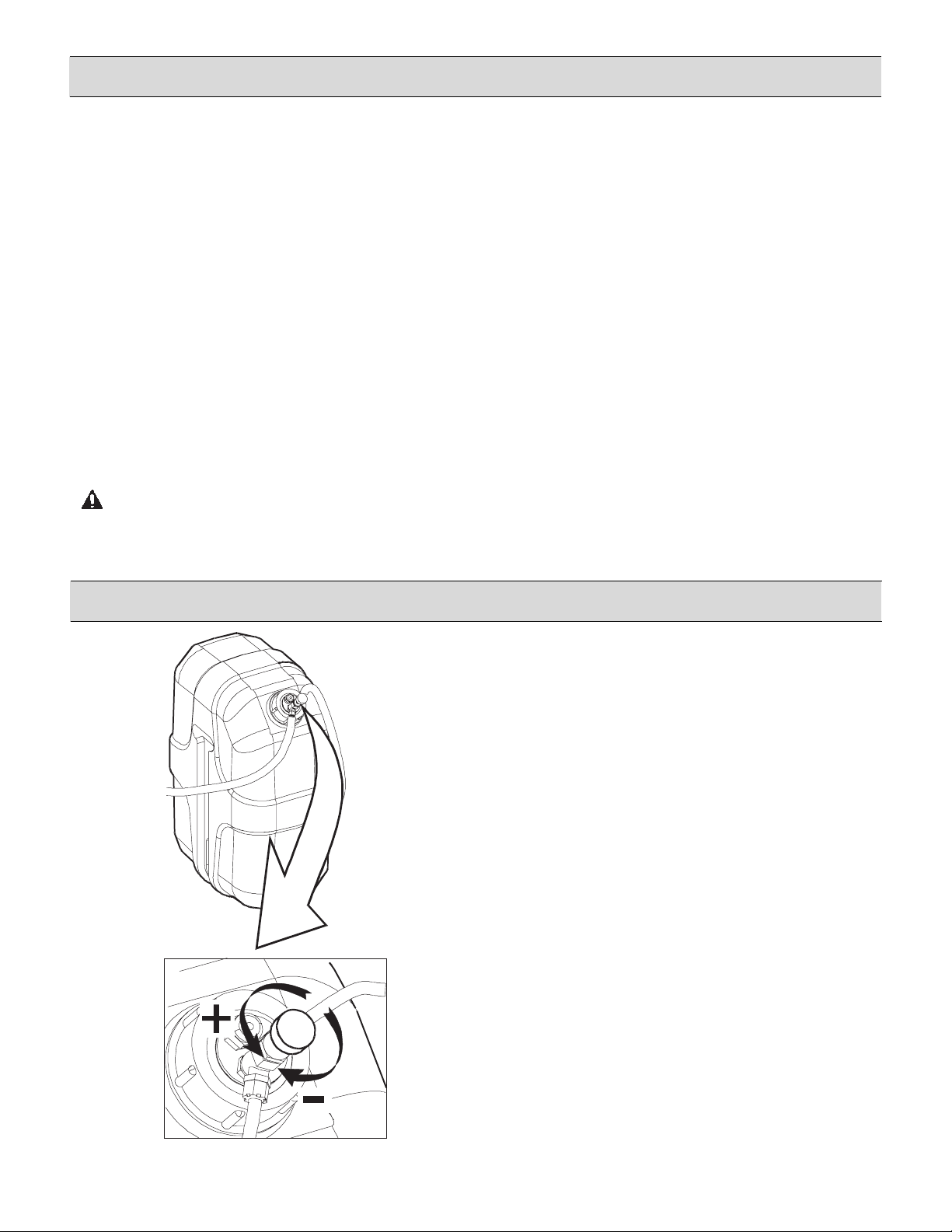
Opening the tank cap may cause foaming agent to suddenly
come out!
This symbol draws special attention to operations where it
is necessary to:
• cut off the supply to the foam marker;
• lift the ring of the pressure relief valve on the tank cap and
discharge the remaining pressure as shown in the illustration.
California Proposition 65 Warning -- This pr duct and related access ries c ntain chemicals kn wn t the
State f Calif rnia t cause cancer, birth defects r ther repr ductive harm.
- 3-
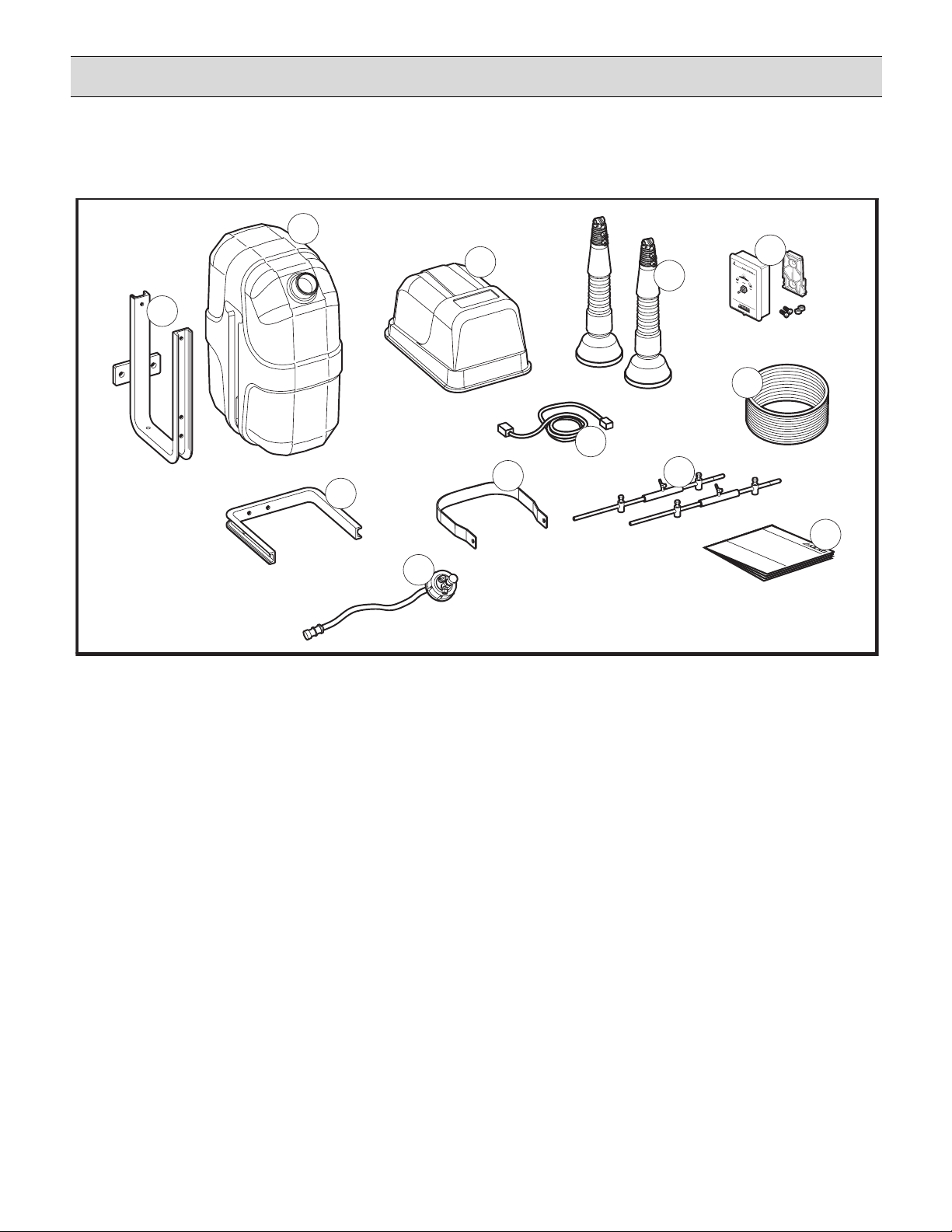
Foam arker Kit Contains:
TRACCIAFILE
R
1
10
9
6
5
12
3
2
SPRAYINGAN D IRRI
GATI
ONSPRAYINGANDI
RRI
GATI
ON
11
7
4
8
1. Complete tank cap assembly
2. Compressor mounting frame
3. Tank bottom support
4. 5-gallon tank
5. Complete compressor unit
6. Nozzle drop assembly
7. Switch box assembly, foam marker
8. Dual hose, 6 mm x 33 M (108')
9. Mounting parts for drop assembly
10. nstruction manual
11. Tank top bracket
12. Console-to-compressor cable
Note: Refer to pages 12 through 15 for individual part numbers.
- 4-
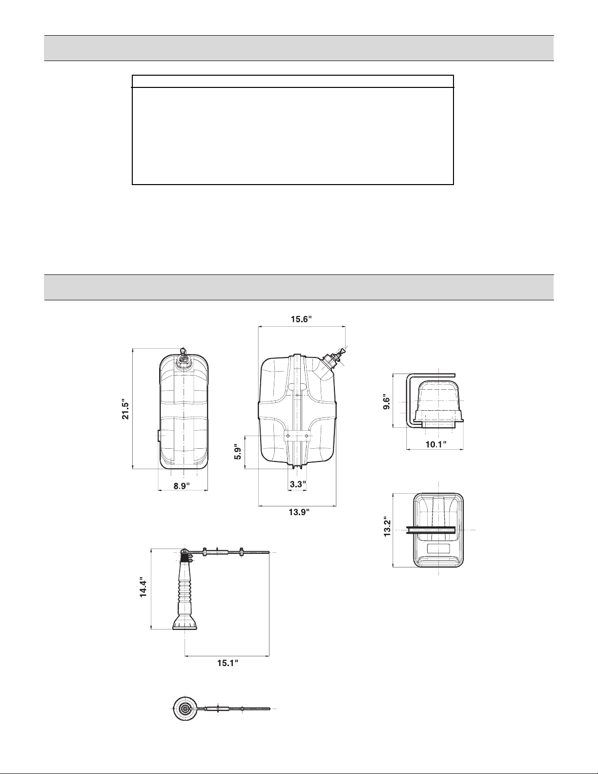
Technical and Operating Specifications
Overall Dimensions
Description Value
Power supply voltage . . . . . . . . . . . . . . . . . . . . . . . . .12 Vdc
Current draw (at 12 Vdc) . . . . . . . . . . . . . . . . . . . . . .9 A
Working temperature . . . . . . . . . . . . . . . . . . . . . . . . .0 - 104°F
Tank capacity . . . . . . . . . . . . . . . . . . . . . . . . . . . . . . .5 gallons
Working pressure (at 12 Vdc) . . . . . . . . . . . . . . . . . .10 PS
Pressure relief valve setting . . . . . . . . . . . . . . . . . . . .14.5 PS
Total weight excluding packing . . . . . . . . . . . . . . . . . .40 lbs.
Noise level . . . . . . . . . . . . . . . . . . . . . . . . . . . . . . . . .75 dB (A)
- 5-
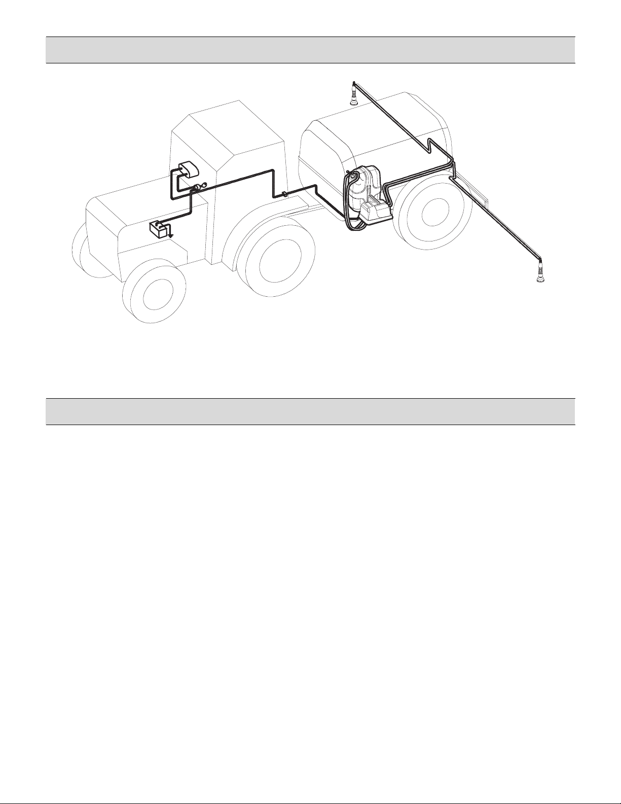
System Installation
Precautions:
When installing the foam marker, it is necessary to observe a few essential rules.
• Secure the electric compressor unit in a position sheltered from stones picked up by the wheels or by the products
sprayed from the booms.
• On seeders, install the electric compressor unit sheltered from areas that are too dusty.
• Using the clamps supplied, fit the air-liquid foam nozzles at the end of the booms at a distance from the last nozzle
equal to half the distance of the spray tips. The foam must fall in an area sheltered from the nozzle, and the point
where it falls must mark the area sprayed by the boom.
• Secure the hoses to the framework with clamps, in a position protected from possible impact with the ground or
with the boom framework. At the joints of the booms, the hoses must be of such a length as to allow the booms to
open and close without damaging the hoses.
• Place the tank upright with the cap easily accessible for filling and adjusting the flow rate.
• nstall the tank so it’s possible to remove for periodical washing.
• The cover of the electric compressor must be easy to remove for maintenance work.
Foam arker Installation
Installing the foam marker on a sprayer

- 6-
ounting the Electric Compressor and Tank
ounting Foam Nozzles or Air-Liquid ixers
The electric compressor and tank can be
mounted on the machine in two different
ways (see illustration at left).
Option 1
When joining the electric compressor unit “D” to the
foaming liquid tank “A,” place the spacers “B” and
fixing bracket “C” between them.
Option 2
nstall the compressor unit “D” and the tank “A” in
different locations according to your own needs.
n this case, it is possible to secure the bed of the
electric compressor to the machine, or to use the
bracket “C”.
The foam nozzle or air-liquid mixers must be
mounted at the end of the booms as follows:
• On boom “A”, make 2 holes at a center distance
of 4.5” using a drill with a bit Ø 6 mm.
• Secure the supports “B” to the boom using M6
screws of an appropriate length.
• nsert the foam nozzle “H” on the knurled portion
of the support rod “F” and secure with the screw
supplied “G.”
• nsert the support rod “F” into the supports “B.”
• Mount and tighten the wing nut “E” on the spacer
“D.”
n this way, the foam nozzle will “rotate.”
To make the foam nozzle “fixed,” mount and tighten
the screw “C” on the support “B.”
• Repeat the above operations for the other boom
as well.
Mounting foam nozzle onto the boom

- 7-
ounting the Liquid/Air Circuit
ounting the Control Unit
Connect the white hoses (air) and the dark blue
hoses (liquid) to the mixing sprayer farthest from
the electric compressor unit, making sure the
hoses and fittings are the same color.
Lay the hoses along the framework of the boom as
far as the electric compressor unit, allowing extra
by the hinges. Connect the hoses to the electric
compressor, respecting the hose/fitting coloring.
Connect the closest foam nozzle to the electric
compressor unit, repeating the above procedure.
Connect the dark blue hoses (liquid) and the white
hoses (air) to the fittings of the same color on the
tank cap.
nsert the hose onto the cap with the bottom filter
at the end.
1. Secure the control box in the cab in a position that
is easy to reach from the driver’s seat.
2. Connect the two-pin outlet connector (58) to an
ignition circuit capable of providing a continuous
load of 10A. Make the connections shown in
Section A. Otherwise, insert a relay as shown in
Section B.
3. Protect the line with a 10A fuse.
4. Use cables with at least 13 gauge or larger.
5. To avoid the risk of short circuits, do not connect
the supply cable connector until installation has
been completed.
6. Connect the control box with the electric
compressor unit using the extension cable supplied.
7. Secure the electric cables, making sure that the
electric connections are mounted in a protected
position.
Supply cable connection

- 8-
Final Testing
Using the Foam arker
1. Put some liquid in the tank.
2. Fully screw the cap onto the tank.
3. Start the electric compressor positioning the selector (“A” on illustration below)
on the right.
4. After a few seconds, check that the liquid is coming out of the right-hand foam
nozzle.
5. Check the correct seal of the hydraulic couplings.
6. Shift the selector to the left (“A” on illustration below) and repeat operations
4 and 5.
7. Stop delivery by positioning the selector to OFF (middle).
8. Discharge the remaining pressure from the tank as shown on page 2.
9. Empty the water from the tank.
10. Clean the circuit as described in the maintenance section.
Control devices
A. Control lever selector — to distribute the foam (Left /Off /Right)
B. Fuse (10A) is located in back of console
A . Lever control switch for foam delivery
(Left / Off / Right)
B. Pilot lights checking and controlling the treated portion
Control Unit
- 9-
Foam arker Operation
aintenance
Preliminary Checks
After a long period of inactivity, it is recommended to
check the tightness of the seal fittings.
Preparation and Solution
• Pour an amount of concentrated foaming liquid into the
tank according to the instructions given on the package
of the product.
• Add clean water to fill the tank. Use a hose inserted
down to the bottom of the tank to mix the product well
and prevent foam from forming. Otherwise, it is
necessary to mix carefully after filling the tank.
• Screw on the cap and tighten it carefully.
• To use it in wintertime, add windshield washer in the
amounts indicated on the package.
Starting and Operation
• Start up the compressor with the lever selector A, on
the control panel. After a few seconds, the circuit will
reach its working pressure, making foam come out of
the selected foam nozzle.
• Adjust the intensity of the foam outlet, using the flow-
rate regulator on the tank cap.
• During use, it is possible to alternate the right- or left-
hand foam nozzle by moving the selector lever.
• To stop operation of the foam marker, turn the selector
lever to the OFF position (middle).
• To finally stop the supply to the foam marker, turn the
starter key to the OFF position (if the electrical
connections described in the “ ounting control unit”
section have been made).
Topping up Liquid
• Discharge the remaining pressure from the tank as shown on page 2.
• Refill with liquid, observing the procedures described in the “Preparation and Solution” section.
Flo -rate Adjustment
Pressure Relief Valve
The pressure relief valve on the tank cap needs
no maintenance. Adjusting the pressure discharge
ring under the tank cap prevents incrustations from
forming on the pressure relief valve. At the same
time, it checks efficiency.

- 10 -
aintenance (Continued)
achine down for up to seven days
For periods of inactivity of up to seven days, carry out the
following operations:
• Slacken the band “B” and remove the diffusor “A.”
• Remove the grid “C” by turning it counterclockwise.
• Take the sponge “D” out of the foam nozzle.
• Carefully wash the foam diffusers and sponge with
water.
• Reassemble the parts. Use care when inserting the
sponge as it must go freely into its seat without crushing,
which would alter the operation of the foam marker.
• Repeat the above operations for the other foam nozzle
as well.
achine down for up to 30 days
For periods of inactivity of up to 30 days, carry out the
following operations:
• Slacken and remove the cap “C.”
• Remove the screws “A,” and take off the tank bracket “B.”
• Remove the tank, and wash with clean water.
• Wash the bottom filter “D.”
• nsert the tank into the support bracket.
• Add a few liters of water to the tank, and put the cap
back on.
• Restore the electrical connections.
• Wash the hydraulic circuit. Operate the lever selector
alternately in the position corresponding to the boom
section involved until clean water comes out of the
diffusers.
• Slacken and remove the cap, and empty the tank
of the remaining water.
• Dismantle the water/air hoses from the cap and join
them using the section of hose supplied.
• Empty the hydraulic circuit by operating the lever
selector in the position corresponding to the boom
section involved until only air comes out of the diffusers.
• Fit all the parts back together to restore the initial
conditions.
• Carry out the operations described in the “Machine
down for up to seven days” section above.
Monthly Cleaning
Weekly Cleaning
Table of contents


