Pentair AQUATRAM 90 User manual

IMPORTANT SAFETY INSTRUCTIONS
READ AND FOLLOW ALL INSTRUCTIONS
SAVE THESE INSTRUCTIONS
INSTALLATION AND
USER’S GUIDE
AQUATRAM®90
SWIMMING POOL ACCESS LIFT

AquaTRAM®90 SWIMMING POOL ACCESS LIFT
300 LB. [136 kg] MAXIMUM CAPACITY
MANDATORY – LEAVE THIS MANUAL WITH LIFT OWNER
WARNING
IMPORTANT SAFETY INSTRUCTIONS
1. READ AND FOLLOW ALL INSTRUCTIONS. LIFT SAFETY CAN ONLY BE ENSURED IF THE LIFT
IS INSTALLED AND OPERATED PROPERLY – ACCORDING TO THESE INSTRUCTIONS.
2. WARNING- TO REDUCE RISK OF INJURY, DO NOT PERMIT CHILDREN TO USE OR OPERATE
THIS PRODUCT.
3. WARNING- DO NOT PERMIT CHILDREN TO PLAY ON THIS PRODUCT.
4. WARNING- NEVER APPLY DIRECT WATER PRESSURE TO ELECTRONIC COMPONENTS.
5. DO NOT USE THE AQUATRAM 90 FOR WATER-DRAFTS OVER 11” (DECK TO WATERLINE).
6. NEVER OPERATE THIS LIFT UNDER LOAD WITH NO WATER (DRY POOL).
7. SAVE A COPY OF THESE INSTRUCTIONS.
WARNING
MAKE SURE THE AREA AROUND THE LIFT IS CLEAR BEFORE OPERATING. NEVER
OPERATE THE LIFT WITH ANY PERSON WITHIN THE OPERATING RANGE OF THE LIFT,
INCLUDING ON THE DECK OR IN THE WATER. NEVER MOVE THE LIFT DOWN WHILE
OVER THE DECK. IF THE LIFT COMES INTO CONTACT WITH THE DECK OR A WALL,
RELEASE THE BUTTON IMMEDIATELY OR PRESS THE EMERGENCY STOP BUTTON.
DO NOT ALLOW CHILDREN TO OPERATE THE LIFT WITHOUT SUPERVISION.
CHECK ALL NUTS AND BOLTS FOR TIGHTNESS AND FOR WORN PARTS BEFORE
EACH USE.
AquaTRAM 90 Technical Support
Contact Technical support at:
Sanford, North Carolina (8 A.M. to 5 P.M.)
Phone: (800) 831-7133
Fax: (919) 566-8920
Web sites: visit www.pentaircommercial.com
- READ CAREFULLY-
Check entire box and inside all packing materials for parts. Before beginning
assembly, read the instructions and identify parts using the figures and parts listed in
this document. It is critical that all parts be carefully inspected by the installer prior to
installation to ensure that no damage occurred in transit and that a damaged part is
not used. If any damage occurred in transit, Pentair Commercial Aquatics™
(“Pentair”) must be notified within three days of receipt of unit. Proper installation
cannot be overstressed, as an improper installation voids Pentair’s warranty and may
affect the safety of the user.

AquaTRAM®90 SWIMMING POOL ACCESS LIFT
TABLE OF CONTENTS
PAGE DESCRIPTION
4 PACKING LIST
5 SITE AND POOL DECK REQUIREMENTS
6 CORE-DRILL RETROFIT INSTRUCTIONS
7 NEW-CONSTRUCTION INSTRUCTIONS
8 AquaTRAM 90 ASSEMBLY INSTRUCTIONS
9 24V CONTROL & BATTERY INSTRUCTIONS
10 BATTERY CHARGING & MAINTENANCE
11 AquaTRAM 90 OPERATING INSTRUCTIONS
12-13 SAFETY & CARE FOR YOUR LIFT
14-16 TROUBLESHOOTING GUIDE
17 AquaTRAM 90 PARTS LIST
18 CHAIR & ACTUATOR ASSEMBLY PARTS LISTS
19 WARRANTY
2

THE AquaTRAM®90 SWIMMING
POOL ACCESS LIFT
NOTE: The AquaTRAM 90 POOL LIFT requires a 1.9” ID X 6” bronze anchor with 1” x 4”
fixing anchor. See anchor installation instructions for more information.
1. AquaTRAM 90 POOL LIFT W/ FOOTREST
2. 24V BATTERY
3. HANDSET/REMOTE
4. SAFETY BELT
3

SITE & POOL DECK REQUIREMENTS
This lift is designed for commercial or residential use on in ground pools and spas. This lift is
not designed to clear a wall or obstacle. The lift should be installed on the pool deck where a
straight linear section of the pool wall is at least six (6) feet long. The lift should be installed at a
pool depth (pool deck to pool floor) of no less than 42” but not more than 48 inches. If the edge
of the pool deck curves the anchor system will need to be anchored differently than what these
instructions outline; contact Pentair Commercial Aquatics™ for assistance in this case. The
front anchors of the lift need to be mounted a minimum of 14 inches and no further than 19
inches from the inside pool wall. If your pool or spa has hand rails or other extensions on the
inside of the pool wall, the set back distance must take these into account. Contact Pentair
Commercial Aquatics for assistance in these types of applications.
In order to properly install this anchor system into an existing pool deck, your pool deck MUST
be at least 3’-3” long, by 3’-3” wide and 10 inches thick. It must also be reinforced with #4 rebar
on 10 inch centers in both directions. There may be instances where your existing pool deck
may not be structurally sound enough or does not meet the minimum requirements outlined
above for the safe installation of this anchor system. In those circumstances it is recommended
that you follow the Saw Cutting Retro-fit Instructions on page 6. If you are installing this lift in a
new application where the pool deck has not been poured yet, then go to the New Construction
instructions on page 7.
FIGURE 1
4

ANCHOR INSTALLATION: OVERVIEW
The AquaTRAM®90 Swimming Pool Access Lift can be installed with the chair
on either side, for clockwise or counterclockwise rotation into the pool. However,
for the round-post version the anchor will have to be installed specifically for one
or the other. Before installing the anchor please review the diagram below to see
which orientation the anchor(s) will be installed in for your application.
5

ANCHOR INSTALLATION: RETROFIT INSTRUCTIONS
The AquaTRAM®90 Swimming Pool Access Lift should be installed in a deck or footing
with the following specifications:
1. MINIMUM FOOTING SIZE: 3’ - 3” x 3’ - 3” x 10” THICK.
2. MINIMUM CONCRETE STRENGTH: 2500 PSI
3. REINFORCEMENT: #4 REBAR @ 10” ON CENTER (O.C.)
To ensure adequacy of an existing pool deck a 3’ – 3” square portion of the existing deck
may be saw-cut, removed and replaced with a footing as specified above. The new slab
reinforcing shall be drilled and epoxied into the existing slab as shown on the next page.
If your deck or footing does not meet these requirements please call Pentair for
recommendations. For decks that meet these requirements follow these instructions to
install your anchor.
TOOLS & MATERIALS REQUIRED:
CORE DRILL MARKING PEN
3” CORE DRILL BIT AIR NOZZLE & PUMP/COMP.
HEAT GUN (OPTIONAL) EPOXY (ANCHOR ADHESIVE)*
1-1/2” CORE DRILL BIT MASKING TAPE
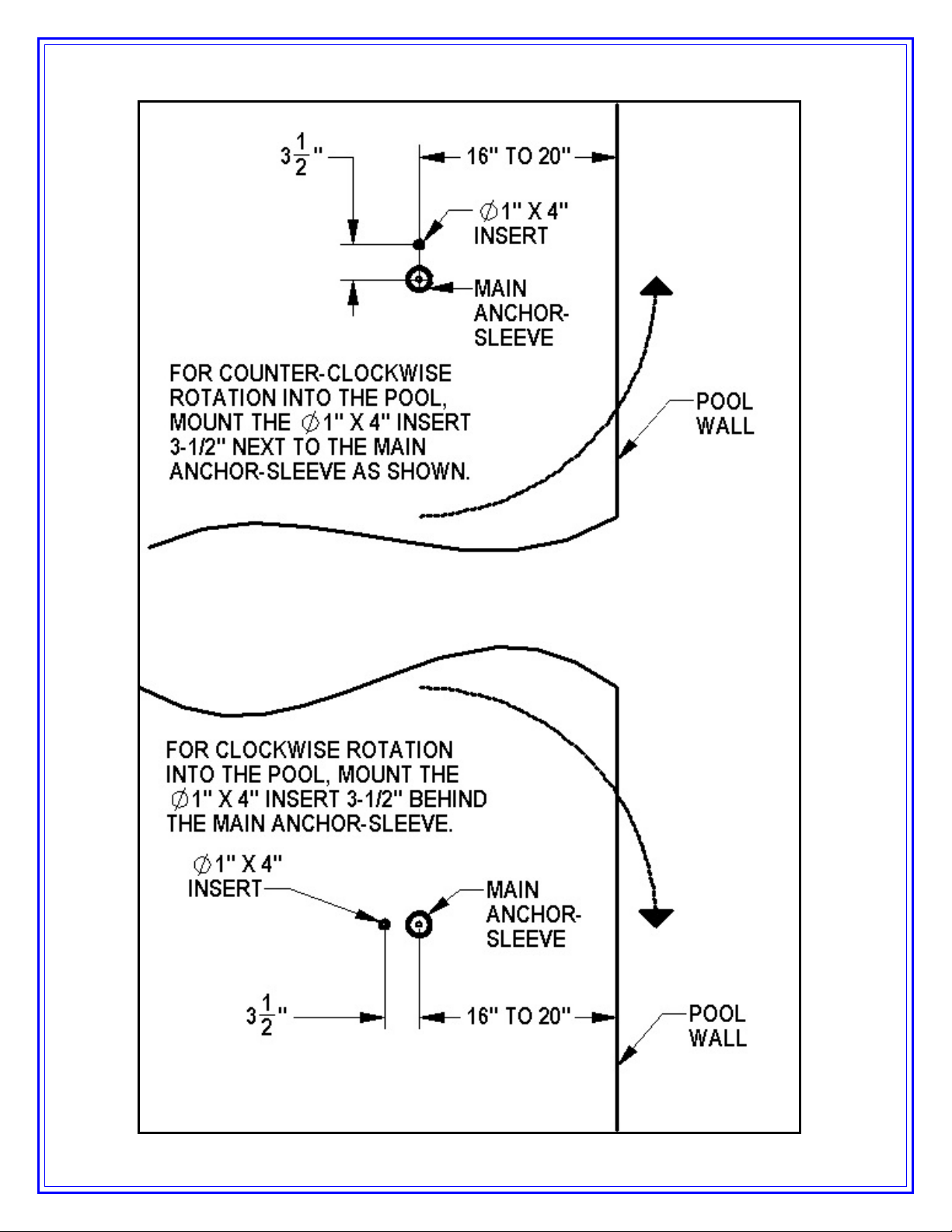
1. Select an anchor location using the diagram on page 8 and the ADA guidelines
on page 4. Mark the center of the main anchor location with a pen or marker.
Refer to the drawing on the next page to determine which side the fixing anchor
will go on, and then mark the center of the fixing anchor 3-1/2” from the center of
the main anchor in the appropriate direction.
2. Using a 3” diameter core-drill bit drill a 3” diameter hole at the main anchor
location. Make sure to keep the bit square to the deck. Drill straight down to a
depth of at least 6”. Change to the 1-1/2” core-drill bit, and drill straight down at
the fixing-anchor location. Drill down to a depth of at least 4”.
3. Remove plugs and clean out the holes with a wire brush, and then insert an air
nozzle to the bottom of the hole and blow out the hole using a pump or
compressed air. Proper hole-cleaning is essential. If the hole is wet, dry it out as
much as possible. A heat-gun may be helpful in drying out the hole.
4. Mask the top of the anchors so that no epoxy gets inside the anchors.
5. Place the anchor in the hole and ‘dry-fit’ it first to make sure the anchor will be
flush and plumb with the deck when installed. Adjust the hole as needed.
6. Install the epoxy into the dispenser and follow manufacturers’ instructions to
ensure that the epoxy is properly mixed and applied. USE ONLY THE
RECOMMENDED EPOXY AND ALWAYS FOLLOW THE INSTRUCTIONS SO
THAT FULL STRENGTH IS ACHIEVED.
7. Inject epoxy adhesive into the hole, starting at the bottom, until the hole is 1/3 to
1/2 full.
8. Install the anchor into the hole/epoxy and push down until it is flush with the deck
surface. Clean off any excess epoxy. Adjust the anchor as needed to make sure
it is flush and plumb with the deck surface. This should be done during the
adhesives’ specified ‘gel time’ (see manufacturers’ instructions).
9. Let the epoxy cure for at least 24 hours before installing the lift (or where
applicable according to the manufacturers’ instructions).
*Use HILTI RE-500-SD adhesive anchor or SIMPSON SET-XP anchor adhesive or
equivalent.
6

7

ANCHOR INSTALLATION: NEW CONSTRUCTION
For new construction a footing should be poured according to the diagram below.
Again, make sure the anchor is installed flush and plumb with the deck surface.
Again, the footing should have the following specifications:
4. MINIMUM FOOTING SIZE: 3’ - 3” x 3’ - 3” x 10” THICK.
5. MINIMUM CONCRETE STRENGTH: 2500 PSI
6. REINFORCEMENT: #4 REBAR @ 10” ON CENTER (O.C.),
EACH WAY, TOP & BOTTOM
8

AquaTRAM®90 - ASSEMBLY INSTRUCTIONS
1. Attach Seat belt to the seat as shown.
2. Install the AquaTRAM 90 Swimming Pool
Access Lift into the anchor location on the
concrete pad.
3. Plug the handset cable into the large handset
socket on the bottom of the control box. Be
sure you press the cord end firmly into the
socket until you are sure it is all of the way into
the socket. Failure to fully push the remote cord
into the socket may result in faulty or
interrupted operation.
4. Before installing the battery, place it on the
charging unit and let it charge for 24 hours.
Make sure the orange “charge” light illuminates
when the battery is being charged.
5. Remove the fully-charged battery from the charger and install it on top of the
Control Box. The battery will line up square with the control box, and will
‘click’ when it locks in place properly. The lift will only operate when the
battery is mounted properly.
WHEN NOT IN USE STORE THE BATTERY ON THE CHARGER. DO NOT
LEAVE THE BATTERY ON THE LIFT WHEN NOT IN USE!
9

24-VOLT BATTERY SYSTEM OPERATING AND
INSTALLATION INSTRUCTIONS
The AquaTRAM®90 Swimming Pool Access Lift comes with a 24v sealed rechargeable
battery, wall mount charging unit (with mounting bracket), control box, and a waterproof
handset controller. The control box is mounted to the AquaTRAM 90 Pool Liftand has a
plug-in socket for both the actuator and the handheld controller. The battery mounts
directly above the control box with a quick-release clip.
To operate the AquaTRAM 90 Pool Lift, plug in the handset controller to the control box
and push the corresponding button to either lower or raise the unit. The lift should be
able to complete approximately 10-20 full cycles before the low battery indicator tone will
sound. The low battery tone indicates that there is approximately 20% battery life
remaining. At this point, DO NOT ATTEMPT TO OPERATE THE LIFT, remove the
battery from the unit and recharge on the wall mounted charging unit.
To recharge the battery, simply grip the top of the battery and depress the clip on the
back of the battery. This will unclip the battery from the control box bracket and the
battery can then be clipped into the wall mount charger. When the charger is plugged in
the green ON light will illuminate. When the battery is correctly mounted to the charger,
the orange CHARGE light will illuminate. When the battery is fully charged, the
CHARGE light will GO OFF and the battery is ready for use.
WHEN THE BATTERY IS NOT BEING USED IT SHOULD BE STORED ON THE
CHARGER AND NEVER ON THE LIFT.
10

BATTERY MAINTENANCE
1. RECHARGE THE BATTERY AS OFTEN AS POSSIBLE. The battery power unit
is a sealed lead acid battery pack. Frequent recharges will prolong the battery life
and maintain a high cold amperage capacity. THE BATTERY CAN BE STORED
ON THE CHARGER WHEN NOT IN USE.
2. Do NOT expose the battery to freezing temperatures.
3. Do NOT expose the battery to prolonged periods of extreme heat or severe cold
temperatures.
4. Do NOT expose the battery to long periods of direct sunlight. Heat will shorten
your battery life. Optimum operating temperature is below 20 degrees Celsius
(68 degrees F.)
5. Never drop or bump the battery pack. This may result in loose or damaged
internal connections, and may bend the battery terminals.
6. Keep battery terminals clean and free from dirt and corrosion to ensure good
contact. The terminals may be cleaned using Scotch Brite or any similar product.
Clean off any corrosion or discoloration on the very top surfaces of the battery
contacts and then apply dielectric grease (supplied with lift) as shown in the
figure below.
USING THE “EMERGENCY BUTTON” on the Pool Lift Control Box
On the front side of the control box is a small recessed
button marked “emergency”. Take a pen or pencil or
other pointed object and depress the “emergency”
button. This will bypass the remote control and send a
signal directly to the actuator to raise the seat out of the
pool and back to the deck or up position.
NOTE: This function will only work if there is
sufficient power in the battery, the battery is properly
attached to the control box, and the control box must
be operating properly.
11

LIFT OPERATION:
Before operating the AquaTRAM®90 Swimming Pool Access Lift for the
first time, the user or operator should become familiar with the Handset
Control and its functions. The figure to the left gives a quick explanation of
the four buttons and their function. For example, to move the lift UP, press
the top left button with the ▲ symbol and hold it down until the lift has
reached its desired height and then release the button. The other buttons
work in a similar fashion. In all cases, releasing the button will cause the lift
to stop moving.
•TO MOVE UP PRESS AND HOLD
THE ▲ BUTTON. TO STOP MOVING
UP RELEASE THE BUTTON.
•TO MOVE DOWN PRESS AND HOLD
THE ▼ BUTTON. TO STOP MOVING
DOWN RELEASE THE BUTTON.
•TO MOVE LEFT PRESS AND HOLD
THE◄►BUTTON. TO STOP MOVING
LEFT RELEASE THE BUTTON.
•TO MOVE RIGHT PRESS AND HOLD
THE►◄BUTTON. TO STOP MOVING
RIGHT RELEASE THE BUTTON.
12

CARE OF YOUR LIFT
Routine cleaning is an absolute necessity to ensure the integrity of the lift. Note that the
AquaTRAM®90 Swimming Pool Access Lift should not be stored in a pump room or in a
storage room where pool chemicals are kept. Storing the lift near pool chemicals may
cause rusting and other damage to occur. Your AquaTRAM 90 stainless steel lift is
powder coated to protect the stainless steel from rusting. Most rusting will occur at weld
points, crevices, under gaskets, rivets or bolt heads.
The choice of a proper cleaning product is up to the consumer and there are many to
choose from. Depending on the type of cleaning and the degree of contamination
(rusting), some products are better than others. For routine cleaning the products most
recommended are gentle soaps or detergents or dilute mixtures of ammonia. For
stubborn spots and stains try using soft scrub with some brisk rubbing.
DO NOT USE POOL WATER TO CLEAN USE ONLY FRESH WATER
If the lift is used DAILY make sure to wash the lift at the end of the day. Wash the lift off
using a mild soap and a soft cloth. Make sure to pay special attention to weld points and
crevices. Do not use a bristled brush or steel wool to clean the lift. Check that the lift is
working properly and then place the battery on the charger. It is recommended that the
battery be charged after every day of use.
If the lift is used WEEKLY follow the same steps as above. Also be sure to check all of
the contact points (terminals) for damage or corrosion. If you notice corrosion gently
clean the terminals. To clean corrosion from the terminals use a q-tip and some rubbing
alcohol. If the corrosion is particularly stubborn try using a 3M scotch brite pad, but be
careful not to damage the terminals. Apply dielectric grease to the terminals after
cleaning them. This will help to prevent further corrosion. Do not leave the battery on
the lift. Always store the battery on the charger whenever the lift is not being used.
SAFETY & MAINTENANCE INSTRUCTIONS
DO NOT PLAY ON OR AROUND THIS LIFT
1. Check the AquaTRAM®Series Pool Liftbefore each use to assure there are no
worn parts and that all hardware is properly tightened. If there are any worn
parts, replace them BEFORE using the AquaTRAM Pool Lift. You can call our
customer service at 1-888-687-3552 to order any parts.
2. Pentair Commercial Aquatics™ lifts shall be grounded per local codes.
3. At least ONCE A WEEK, the AquaTRAM Series Pool Lift must be cleaned with
fresh water. Do not spray the AquaTRAMSeries Pool Lifts’ 24v battery unit
directly with any pressure. Wipe all surfaces clean with a damp, non-abrasive
cloth. When cleaning the AquaTRAM Series Pool Lift, use non-abrasive soap
and water. Avoid harsh chemicals and disinfectants.
4. Always read the label instructions on any cleaner carefully before applying it to a
surface.
5. The WARNING & INTENDED USE labels on the AquaTRAM Series Pool Lift
must be maintained in readable fashion. If they become unreadable or faded,
please replace the label immediately. Replacement labels are available from
AQUA CREEK PRODUCTS LLC. 1-888-687-3552.
13

If the lift is used MONTHLY follow the same steps as above. Also check the nuts and
bolts to make sure they are securely fastened (this is always a good idea, no matter
how often or infrequently the lift is used). Also make sure to store the battery on the
charger and not on the lift. Leaving the battery on the lift for extended periods will
significantly shorten the battery’s lifespan.
If the lift is being STORED for an extended period of time follow all of the steps
above. Check for rusting at all crevice and weld points. If you notice rusting,
apply some mild dish detergent to the affected area and take a 3M scotch brite
pad and rub briskly. Afterwards, be sure to rinse the lift with clean water NOT
pool water. When storing the lift make sure it is in a dry area and covered. DO
NOT STORE in or around pool chemicals.
14

TROUBLESHOOTING GUIDE
Before troubleshooting make sure the battery is fully charged.
If the AquaTRAM®90 Swimming Pool Access Lift doesn’t move when the
handset button is pressed:
When you can’t get the lift to move check the following things:
1. Make sure the battery is fully charged:
A. Before charging the battery first make sure the green light on
the front of the charger is illuminated (this means that the
charger is on). Then check to make sure the silver contact
points on the battery and charger are not damaged or corroded,
and that they are clean. Then place the battery on the charger
and look for the orange charge light to illuminate on the front of
the charger. When the orange light goes off the battery is fully
charged.
B. When the battery is correctly installed on the charger or control
box you should hear a “click” indicating the battery is properly
seated on the unit. Also note that when the battery is properly
seated there should not be any gaps between the battery and
the control box/charger.
The top green light will always
be illuminated indicating that it
has power. When charging the
battery the bottom orange light
will illuminate, until fully
charged.
Not attached properly. Note
the white bracket is in front of
silver clip, which will not allow
for an electrical connection.
Properly Attached.
Note that the white bracket is
behind the silver clip. Not allowing
movement.
15

If the battery is fully charged and the AquaTRAM® 90 Swimming Pool
Access Lift is not moving then:
2. Check all cords:
A. Check that the cords are properly plugged in. Start by
unplugging the remote and the actuator cord from the control
box. Once these cords are removed check the ends for
corrosion or damage. Plug the remote cord back in by lining up
the raised tab on the plug to the grooved line on the control box
outlet. Note that these cords require some force to plug them in
fully. You will know they a correctly inserted when you here a
“popping sound”. The cords will be recessed into the outlet. If
they are flush with the outside of the outlet they are not plugged
in fully and the lift will not function. Make sure you do this for
both cords.
If you have checked all the cords and the lift still doesn’t move:
3. Check the contact points:
A. After you have fully charged the battery and checked the cords
to make sure they are properly plugged in, check to make sure
the contact points are not corroded or bent. If the contact points
are corroded take some rubbing alcohol and a q-tip and clean
off the points. After cleaning the contact points it is
recommended to put some dielectric grease on the contact
points (terminals) to help ensure good electrical contact and
prevent corrosion. Then reinstall the battery on top of the
control box. Make sure you hear a “click”, which indicates that
the battery is correctly seated. The lift will not work if the battery
is not seated correctly.
NOT inserted fully.
Fully inserted.
Silver tabs are the contact
(terminal) points.
16

If the AquaTRAM®90 Swimming Pool Access Lift stops moving over the
water and is stuck:
4. Then try pushing the emergency button:
A. If the lift gets stuck out over the water use a pen or pencil tip
and stick it into the emergency button on the front of the control box
to retract the lift. Note the lift will not retract if the battery is not fully
charged or if the control box is not working. The emergency button
only overrides the remote in case it has gone bad. If this does not
retract the lift then chances are the remote is fine and you either
have a problem with the battery, the control box, or the cords are
damaged or not plugged in properly.
USING THE “EMERGENCY BUTTON” on the AquaTRAM 90 Control Box
On the front side of the control box is a small recessed button marked
“emergency”. Take a pen or pencil or other pointed object and depress the
“emergency” button. This will bypass the remote control and send a signal
directly to the actuator to raise the seat out of the pool and back to the deck or up
position.
NOTE: This function will only work if there is sufficient power in the
battery, the battery is properly attached to the control box, and the control
box must be operating properly.
Use a pen or pencil tip
to push in the small
black circle located next
to the word emergency,
on the front of the
control box.
17

AQUATRAM®90 POOL LIFT: PARTS LIST
18

ITEM NO. QTY. PART NUMBER DESCRIPTION
1 1 P-901 CHAIR, BLUE ROTOMOLDED (18" WIDE)
2 2 P-2100FLA-38 ARMRESTTUBE
3 1 P-1208HSB HANDSETBRACKET, HDPE
4 2 RUBBER HAND GRIPS RUBBER HAND GRIPS, BLACK
5 2 SCREW, #12 X3/4 FHSMS #12 X3/4" FLAT-HD SHEET-METAL SCR SS
6 4 FLAT WASHER, 1/4 SS 1/4" FLAT WASHER, 316 SS
7 2 BOLT, 1/4 X3 1/4 BHSCS 1/4"-20 X3-1/4" BUTTON-HD CS, SS
8 2 NYLOCK, 1/4 SS 1/4"-20 NYLOCK NUT, SS
9 1 COTTER PIN, 1/4 X3 1/4 1/4" X3-1/4" QUICK-PULL PIN FOR FOOTREST
10 1LANYARD SS LANYARD FOR FOOTRESTPIN
11 1SCREW, #10 X3/4 PHSMS #10 X3/4" PAN-HEAD SHEET-METAL SCR, SS
12 1F-38SB SEAT BELT, 2" BLACK W/VELCRO FOR PP
13 2SCREW, #6 X1/2 PHSMS #6 X1/2" PAN-HD SHEET-METAL SCR, SS
CHAIR ASSEMBLY: PARTS LIST
19
Other manuals for AQUATRAM 90
1
Other Pentair Lifting System manuals