manuals.online logo
Brands
  1. Home
  2. •
  3. Brands
  4. •
  5. Pentair
  6. •
  7. Surge Protector
  8. •
  9. Pentair ERICO CRITEC TSF Series User manual

Pentair ERICO CRITEC TSF Series User manual

1. Preparation
Electrical shock or burn hazard.
Installation of this Transient Surge
Filter should only be made by
qualified personnel. Failure to lockout electrical power
during installation or maintenance can result in fatal
electrocution or severe burns. Before making any
connections to the electrical panel, be sure that power
has been removed from all associated wiring, electrical
panels, and other electrical equipment.
The installation of this surge filter should be
1.
installed in accordance with all applicable codes,
such as the National Electrical Code (NEC
®)
, or the
Canadian Electrical Code.
Check to make sure line voltage does not exceed
2.
surge filter voltage requirement. Prior to installation
ensure that the TSF is of the correct voltage,
current, and frequency rating for your application.
The ground / earth terminal must be connected to a
3.
low impedance earth for correct operation.
Do not perform a “Dielectric Withstand” or use a
4.
Mega-Ohm Meter (Megger) to test circuits that are
protected with TSF units. Damage may occur to the
TSF units.
Follow all instructions to ensure correct and safe
5.
operation.
Do not attempt to open or tamper with TSF units in
6.
any way as this may compromise performance and
will void warranty.
2. Introduction
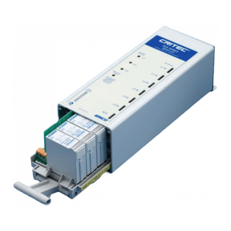
Transient Surge Filters (TSF) are designed for simple
installation onto 35mm DIN rails. They can be selected
for use on distribution systems with nominal RMS
voltages of 120V or 240V at frequencies of 50/60Hz.
The TSF6A24V unit is suitable for 12V and 24Vac/dc
signaling and control systems.
3. Quick Installation Overview
Install in the following manner:
Ensure that power is removed from the area and
1.
the circuits that will be connected.
Snap lock the TSF module to the DIN rail.
2.
Install the appropriate upstream overcurrent
3.
protection (refer to Section 8)
Connect wiring to the indicated input and output
4.
terminals.
4. Protection Concepts
The terminals on the TSF units are labeled
“INPUT/LINE” (unprotected side) and “OUTPUT/LOAD”
(protected side) assuming that the source of the
transients is on the input side of the TSF module.
To optimize effectiveness of the TSF protection, the
unprotected and protected wiring should be separated.
Wiring from the exposed transient source to the TSF
should be considered unprotected and kept
approximately 12” (300mm) from all other wiring
wherever possible. Wiring on the equipment side of the
TSF should be considered protected.
The separation of protected and unprotected wiring is
recommended to minimize the risk that transients on
unprotected wiring may cross couple onto protected
circuits and diminish the level of protection available
from the TSF module.
Table 1: Model and Plug-in Module Part Number
TECHNICAL SUPPORT
www.erico.pentair.com
IP8276_E
1 OF 2
INSTRUCTION SHEET
Pentair, CADDY, ERICO CADWELD, ERICO CRITEC, ERICO, ERIFLEX, and LENTON are owned by Pentair or its global affiliates. All other trademarks are
the property of their respective owners. Pentair reserves the right to change specifications without prior notice.
WARNING:
Pentair products shall be installed and used only as indicated in Pentair product instruction sheets and training materials. Instruction sheets are available at
1.
www.erico.pentair.com
and from your Pentair customer service representative.
Pentair products must never be used for a purpose other than the purpose for which they were designed or in a manner that exceeds specified load ratings.
2.
All instructions must be
completely
followed to ensure proper and safe installation and performance.
3.
Improper installation, misuse, misapplication or other failure to completely follow Pentair's instructions and warnings may cause product malfunction, property
4.
damage, serious bodily injury and/or death, and void your warranty.
SAFETY INSTRUCTIONS:
All governing codes and regulations and those required by the job site must be observed.
Always use appropriate safety equipment such as eye protection, hard hat, and gloves as appropriate to the application.
NEC is a registered trademark of, and National Electrical Code (NEC) standard is a copyright of the National Fire Protection Association, Inc. UL, UR, cUL, cUR,
cULus and cURus are registered certification marks of UL LLC.
Transient Surge Filter
ERICO CRITEC TSF Series
© 2016 Pentair All Rights Reserved
NOTE:
The terminals on the TSF units are labeled
Ground / Earth 1,2 (unprotected side) and 7,8
(protected side), Neutral 3,4 (unprotected side) and
9,10 (protected side), and Line 5,6 (unprotected side)
and 11,12 (protected side).
For installations in accordance with the National
Electrical Code (NEC) and UL
®
1449, use the fuse
specified in column A. For installations in accordance
with the International Electrotechnical Commission
(IEC) 60364 and 61643, use the circuit breaker
specified in column B.
Figure 1: Wiring Diagram
Table 2: Fuse Rating and Wire Size
5. Mounting
TSF's are designed to clip onto 35mm DIN rails
(standard EN50022). Unless otherwise mechanically
restrained, use horizontal DIN rails with the snap fit
design of the TSF to mount the unit with the label text
in the correct orientation.
NOTE:
TSF's must be installed in an enclosure or panel
which:
• prevents the TSF unit ambient temperature from
exceeding 104°F (40°C).
• provides adequate electrical and safety protection
• prevents the ingress of moisture and water
• allows the plug-in module visual indication flag to be
inspected
6. Ground Fault Circuit Interruption (GFCI)
Where GFCI protectors (RCD's/ELCB's) are used, it
is preferable that the TSF modules be installed prior
to these devices (i.e. upstream). If this is not done,
nuisance tripping of the GFCIs may occur during
transient activity.
7. Conductor Termination
Each TSF terminal is designed to accept wire sizes
from 14 AWG to 10 AWG (2.5mm
²
- 6mm
²
) solid or
stranded conductors. The wire insulation should be
stripped back .28-.31 in. (7-8mm) before terminating
into the tunnel terminal.
NOTE:
Do not use greater than 7 in-lb (1.0 Nm) of torque
when tightening the terminals.
8. FUSING AND ISOLATION
Overcurrent protection must be installed in the
upstream circuit of every TSF to provide protection to
the unit itself, the load and the wiring in case of fault
situations. The overcurrent protection device and the
wire size used should be determined according to
table 2.
9. Status Indication
TSF modules have a visual indicator flag on the plug-
in module. Should the plug-in module reach end-of-
life the visual indicator flag provides user-feedback.
Refer to figure 2 for visual flag indicator. The TSF
module should be replaced, as optimum protection is
no longer provided. Refer to Table 1 for replacement
module part number information.
10. Maintenance & Testing
The convenient plug-in module and separate base
design facilitates replacement of a failed plug-in surge
module without needing to undo installation wiring. In
the event you are removing the TSF module, ensure
that the power has been removed from the TSF
module before removing a TSF module from service.
Replacement of a TSF module should only be
undertaken by qualified personnel.
NOTE:
TSF units should be inspected periodically, and also
following any periods of lightning or transient voltage
activity. Check the visual indicator flag and replace the
plug-in module if the flag has been activated as in Section 9
Status Indication.
11. Remote Alarm Contact
The TSF has a form C alarm contact for remote
indication of protection status. Refer to figure 3 for
remote alarm plug-in information. The alarm contacts
are rated at 3A @ 125VAC. Use 16 AWG wires to
connect to the M2 contact screws.
Figure 2: Visual Indicator Figure 3: Remote Alarm Contacts
Transient Surge Filter
ERICO CRITEC TSF Series
(1&2) Bussmann FNQR7-1/2 and Mersen ATMR25 are required for UL 1449 certification.
(3&4) Clipsal 4CB106/10 and Clipsal 4CB116/10 were used for IEC 61643-11 testing
TECHNICAL SUPPORT
www.erico.pentair.com
IP8276_E
2 OF 2
INSTRUCTION SHEET
Pentair, CADDY, ERICO CADWELD, ERICO CRITEC, ERICO, ERIFLEX, and LENTON are owned by Pentair or its global affiliates. All other trademarks are
the property of their respective owners. Pentair reserves the right to change specifications without prior notice.
© 2016 Pentair All Rights Reserved

This manual suits for next models

5

Other Pentair Surge Protector manuals

Pentair RTP3034SPG User manual

Pentair

Pentair RTP3034SPG User manual

Pentair ERICO TDX 50C Series User manual

Pentair

Pentair ERICO TDX 50C Series User manual

Popular Surge Protector manuals by other brands

Panamax MAX 5510 ACRegenerator owner's manual

Panamax

Panamax MAX 5510 ACRegenerator owner's manual

Axis T8061 installation guide

Axis

Axis T8061 installation guide

Rice Lake TP232 installation guide

Rice Lake

Rice Lake TP232 installation guide

Nivus EnerPro operating instructions

Nivus

Nivus EnerPro operating instructions

Nitek IPPWR1 Installation and operation manual

Nitek

Nitek IPPWR1 Installation and operation manual

Energenie SPG5-C-5 user manual

Energenie

Energenie SPG5-C-5 user manual

Transtector ALPU-EXLT installation instructions

Transtector

Transtector ALPU-EXLT installation instructions

RST Solar PV T1+T2 G 1000V DC installation manual

RST

RST Solar PV T1+T2 G 1000V DC installation manual

Quark-Elec QK-AS15 manual

Quark-Elec

Quark-Elec QK-AS15 manual

Stratitec MultiStage S3002 Instructions for use

Stratitec

Stratitec MultiStage S3002 Instructions for use

Siemens 5SD7463-0 Operating	 instruction

Siemens

Siemens 5SD7463-0 Operating instruction

Adcom ACE-515 owner's manual

Adcom

Adcom ACE-515 owner's manual

SurgeX SX1115RT installation instructions

SurgeX

SurgeX SX1115RT installation instructions

Danfoss MCC 101 Installation guidelines

Danfoss

Danfoss MCC 101 Installation guidelines

CFH CFHSO0100 installation guide

CFH

CFH CFHSO0100 installation guide

AETEK SD-404-V2 Quick installation guide

AETEK

AETEK SD-404-V2 Quick installation guide

Foresight CCTV SP006P user manual

Foresight CCTV

Foresight CCTV SP006P user manual

Sven SF-08E-16 user manual

Sven

Sven SF-08E-16 user manual

manuals.online logo
manuals.online logoBrands
  • About & Mission
  • Contact us
  • Privacy Policy
  • Terms and Conditions

Copyright 2025 Manuals.Online. All Rights Reserved.