Pentax IPFC 109 User manual

Operating manual
IPFC
manIPFC_eng_30

2
Index
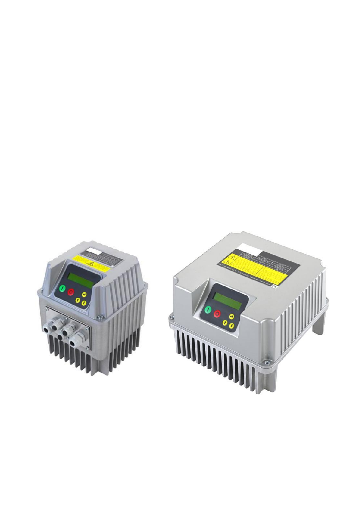
1. IPFC Introduction............................................................................................................................................................... 3
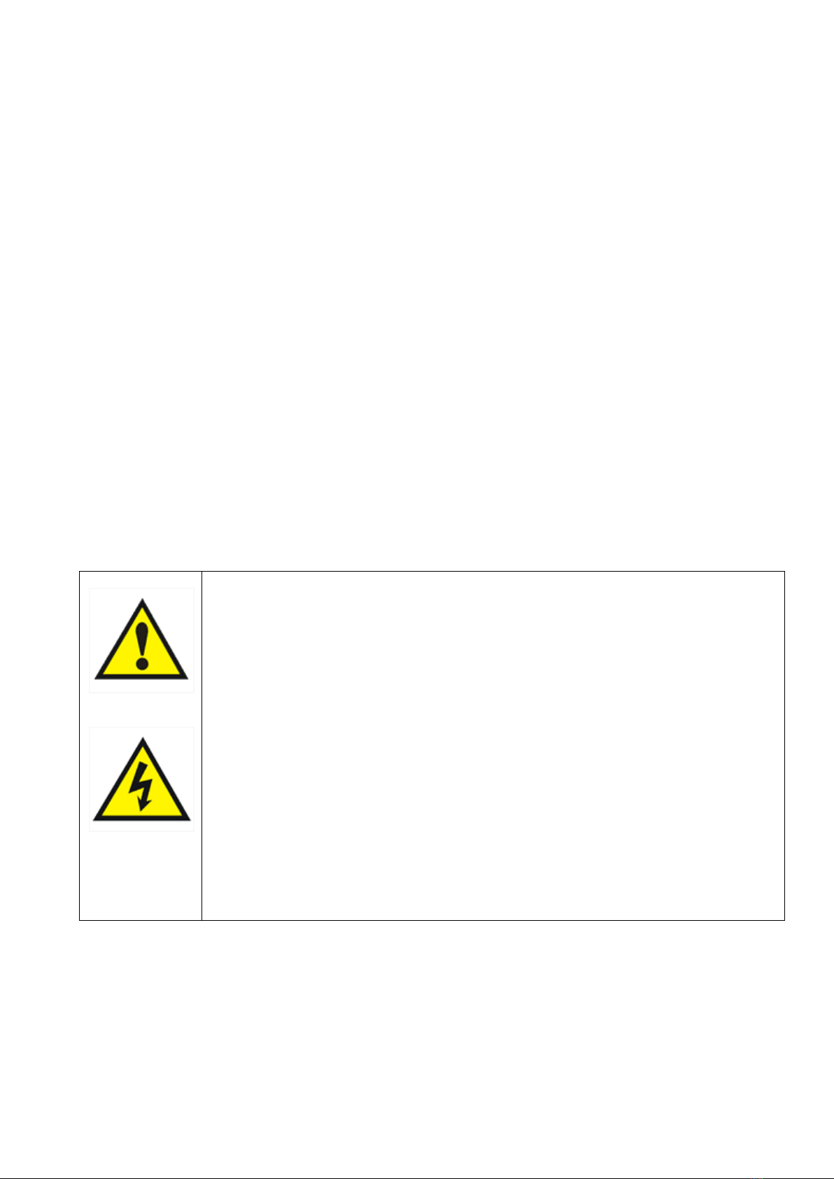
2. Safety Instructions............................................................................................................................................................. 3
3. Technical Characteristics ................................................................................................................................................... 4
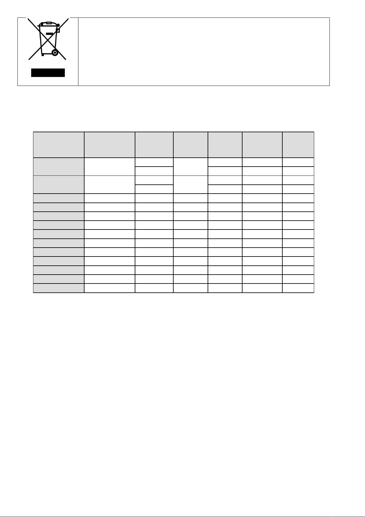
3.1 Weight and dimensions .......................................................................................................................................................... 5
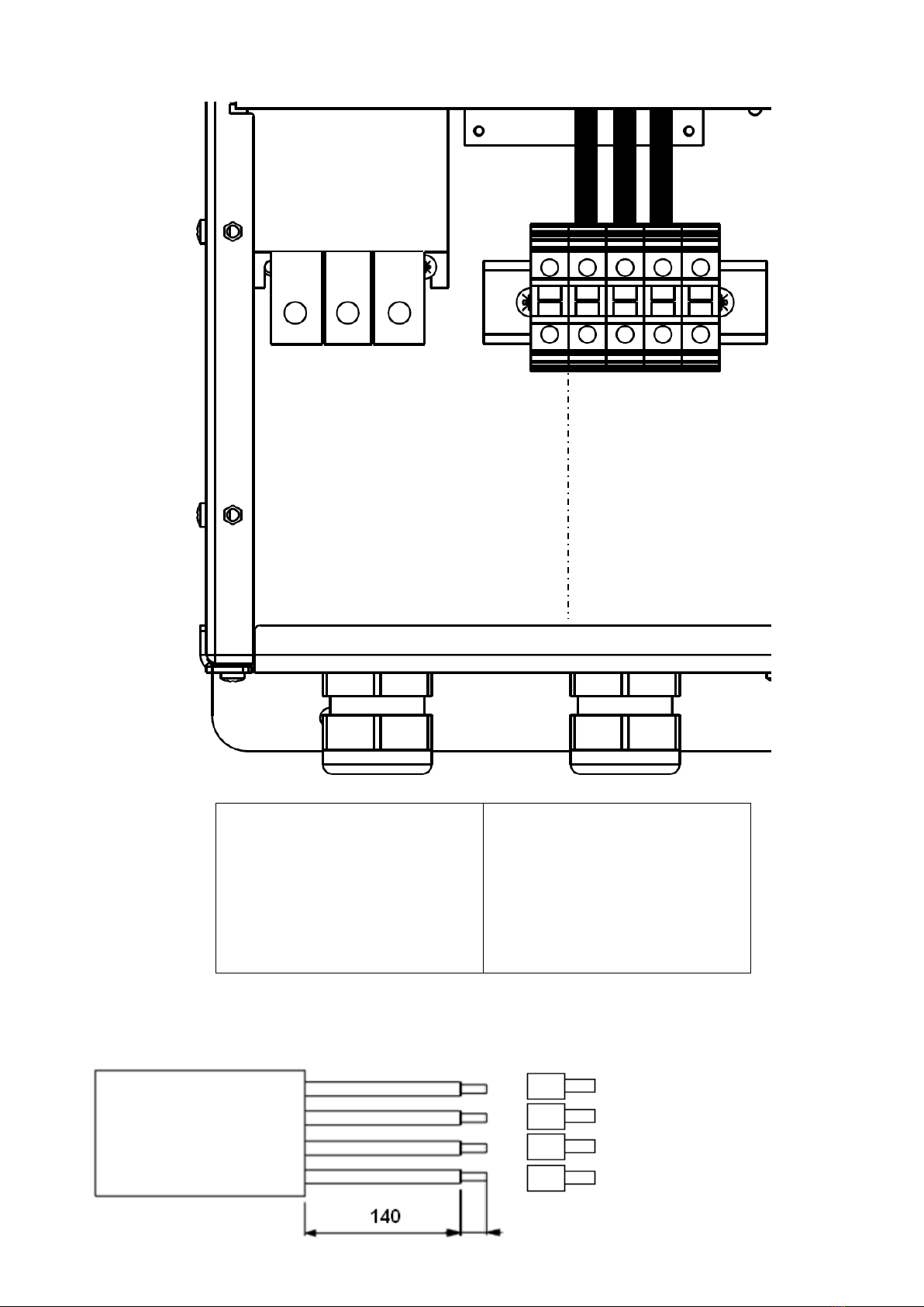
4. Electric wiring.................................................................................................................................................................... 6
4.1 Protections............................................................................................................................................................................. 11
4.2 Electromagnetic compliance.................................................................................................................................................. 11
4.3 Installation with long motor cables ....................................................................................................................................... 11
5. IPFC installation................................................................................................................................................................12
5.1 IPFC Installation for constant pressure control...................................................................................................................... 15
5.1.1 Pressure tank .............................................................................................................................................................. 15
5.1.2 Pressure sensor........................................................................................................................................................... 15
5.2 IPFC installation for differential constant pressure applications ........................................................................................... 16
5.2.1 Sensors wiring ............................................................................................................................................................. 16
5.2.2 Programming............................................................................................................................................................... 16
6. IPFC Use and Programming...............................................................................................................................................17
6.1 IPFC display ........................................................................................................................................................................... 17
6.2 Initial configuration............................................................................................................................................................... 17
6.2.1 FOC motor control ...................................................................................................................................................... 19
6.3 Initial view ............................................................................................................................................................................. 21
6.4 Menu view............................................................................................................................................................................. 22
6.5 Control parameters ............................................................................................................................................................... 22
6.6 Motor parameters.................................................................................................................................................................. 26
6.7 IN/OUT parameters................................................................................................................................................................ 29
6.8 Connectivity parameters........................................................................................................................................................ 30
7. Protections and alarms.....................................................................................................................................................30
8. Auxiliary pumps during constant pressure control ...........................................................................................................32
8.1 DOL pumps............................................................................................................................................................................ 33
8.2 COMBO function .................................................................................................................................................................... 34
9. Trouble-shooting chart .....................................................................................................................................................37
10. Technical Assistance .......................................................................................................................................................38

3
1. IPFC Introduction
IPFC is a variable frequency drive designed to control and protect pumping systems by varying the output frequency to the
pump.
IPFC can be applied to both new and existing pumping systems, and provides:
energy and cost savings
simplified installation and an overall lower pumping system cost
longer life of the pumping system and relevant components
improved reliability
IPFC, when connected to any pump, manages the system operation to maintain a certain constant physical quantity
(pressure, differential pressure, flow, temperature, etc.) regardless of the conditions of use. The pump is operated only when
needed thus avoiding unnecessary energy consumption.
IPFC at the same time is able to:
protect the motor from overload and dry running
implement soft start and soft stop to increase the system life and reduce current peaks
provide an indication of current consumption, voltage, and power
maintain a record of run time and display any errors and/or failures reported by the system
control up to two additional pumps at a constant speed (Direct On Line)
connect to other IPFC units for combined operation
Through the use of inductive filters (optional) IPFC eliminates dangerous surges that are induced in long cables, making IPFC
suitable for control of submersible pumps.
2. Safety Instructions
The manufacturer strongly suggests carefully reading this operation manual before using and installing its products
Any operation (installation, maintenance and repair) must be carried out by trained, skilled, and qualified personnel.
Failure to observe and follow the instructions in this manual may result in dangerous and potentially lethal electric shock.
Pay attention to all standard safety and accident prevention regulations
The device must be connected to main power supply via a switch to ensure the
complete disconnection from the network before any operation on the IPFC itself
(including visual inspection) and/or on the connected load.
Disconnect IPFC from the main power supply before commencing any work.
Do not remove, for any reason, the cover and the cable plate without having first
disconnected the device from the main power supply and having waited at least
5 minutes.
IPFC and pumping system must be grounded properly before operation.
For the entire period IPFC is powered, high voltage is present on the output
terminals of the inverter whether or not the pump is running.
Tightening all screws on the cover with washers is recommended before
powering the device. Otherwise, there may be a failure to connect the cover to
ground, creating the risk of electric shock or even death.
Avoid any shock or significant impact during transport.
Check the IPFC immediately upon delivery and check for damage and/or missing parts. If either occurs, immediately notify
the supplier.
Damages due to transport, incorrect installation, or improper use of the device will null and void the warranty.
Tampering or disassembly of any component will automatically void the warranty.
The manufacturer cannot be held responsible for any damages to people and/or property due to improper use of its
products.

4
Devices marked with this symbol cannot be disposed of in household waste but
must be disposed of at appropriate waste drop-off centres. It is recommended
to contact the Waste Electrical and Electronic Equipment drop-off centres
(WEEE) in the area. If not disposed of properly, the product can have potential
harmful effects on the environment and on human health due to certain
substances present within. Illegal or incorrect disposal of the product is subject
to serious administrative and/or criminal penalties.
3. Technical Characteristics
Model
Vin +/- 15% [V]
Max V out
[V]
Max I in
[A]
Max I out
[A]
P2 motor
power*
[kW]
Size
IPFC 109
1 x 230
1 x Vin
15
9
1,1
1
3 x Vin
7
1,5
1
IPFC 114
1 x 230
1 x Vin
20
9
1,1
1
3 x Vin
11
3
1
IPFC 306
3 x 380 - 460
3 x Vin
10
6
2,2
1
IPFC 309
3 x 380 - 460
3 x Vin
13,5
9
4
1
IPFC 314
3 x 380 - 460
3 x Vin
16
14
5,5
2
IPFC 318
3 x 380 - 460
3 x Vin
21
18
7,5
2
IPFC 325
3 x 380 - 460
3 x Vin
31
25
11
2
IPFC 330
3 x 380 - 460
3 x Vin
35
30
15
2
IPFC 338
3 x 380 - 460
3 x Vin
42
38
18,5
3
IPFC 348
3 x 380 - 460
3 x Vin
52
48
22
3
IPFC 365
3 x 380 - 460
3 x Vin
68
65
30
3
IPFC 375
3 x 380 - 460
3 x Vin
78
75
37
3
IPFC 385
3 x 380 - 460
3 x Vin
88
85
45
3
Power frequency: 50 - 60 Hz (+/- 2%)
Max. ambient temperature at nominal current: 40°C (104 °F)
Max. altitude at nominal current: 1000 m
Grade of protection: IP55 (SIZE 1,2) , IP54 (SIZE 3) *
RS485 serial communication
* auxiliary cooling fan of the IPFC, used in wall mounted applications, has a protection rating of IP54.
IPFC is able to power the motor with a higher current for a short period of time according to the linear relation: 101%
of the nominal current for 10min., 110% nominal current for 1 min.

5
3.1 Weight and dimensions
Model
Weight *
Size
[Kg]
IPFC 109
4
1
IPFC 114
4,3
1
IPFC 306
4,4
1
IPFC 309
4,4
1
IPFC 314
7
2
IPFC 318
7
2
IPFC 325
7
2
IPFC 330
7,2
2
IPFC 338
33
3
IPFC 348
33
3
IPFC 365
34
3
IPFC 375
34
3
IPFC 385
34
3
* Weight without packing.
SIZE 1
SIZE 2
SIZE 3

6
4. Electric wiring
Power board IPFC 109,114
Power supply:
LINE: L1, L2,GND
It is recommended to use cable
lugs
Output:
3 ph motor:
GND,U,V,W,
1 ph motor:
earth, U (running), V (common)
It is recommended to use cable
lugs.
230 V AC auxiliary fans (wall
mounting kit)
FAN: F1, F2
Recommended line and motor cables stripping

7
Power board IPFC 306,309
Power supply:
LINE: GND , L1, L2, L3,
It is recommended to use cable
lugs.
Motor output:
MOTOR: U, V, W, GND
It is recommended to use cable
lugs.
12 V dc auxiliary fan (wall
mounting kit) :
0VE, + VE
WARNING: respect the polarity.
Cable stripping recommended for line input and output to the motor.

8
Power board IPFC 314,318,325,330
Power supply:
LINE: L1, L2, L3, GND
It is recommended to use cable
lugs.
Motor output:
MOTOR: U, V, W, GND
It is recommended to use cable
lugs.
12 V dc auxiliary fans (wall
mounting kit)
VENT: +, -
WARNING: respect the polarity.
Cable stripping recommended for line input and output to the motor.

9
Power board IPFC 338,348,365,375,385
Power supply:
LINE: L1, L2, L3, P.E.
It is recommended to use
cable lugs.
Motor output:
MOTOR: U, V, W, P.E.
It is recommended to use
cable lugs.
Cable stripping recommended for line input and output to the motor.
LINE
L2
L1
P.E.
W
P.E
L3
V
U
MOTOR

10
Control board
Analog inputs (10 or 15 Vdc):
1. AN1: 4-20 mA: sensor 1
2. AN2: 4-20 mA: sensor 2
3. AN3: 4-20 mA / 0 - 10 Vdc (settable
by jumper C.C.): external set
4. AN4: 4-20 mA / 0 - 10 Vdc (settable
by C.C.): trimmer for frequency
regulation / external set 2
Digital outputs:
motor run signal:
NO1, COM1: closed contact with motor running.
NC1,COM1: closed contact with motor stopped.
alarm signal
NO2,COM2: closed contact without alarm.
NC2,COM2: closed contact with alarm or no power
supply.
DOL1 pump relay:
NO3,COM3: closed contact with DOL1 running.
NC3,COM3: opened contact with DOL1 running.
DOL2 pump relay:
NO4,COM4: closed contact with DOL2 running.
NC4,COM4: opened contact with DOL2 running.
Relays are no voltage contacts. Max. voltage to the
contacts is 250 V with max current of 5 A.
RS485 for COMBO:
S1+
S1-
G
It is recommended to
respect the polarity
linking more IPFCs in
series.
Digital inputs:
IN1 : motor start & stop
IN2: value set 1 & 2 switching
IN3: sensor 1 & 2 switching
IN4 : motor start & stop + alarms
reset
0V
We recommend using only no voltage
contacts.
Opening or closing the digital contacts
(depending on software configuration
set (see IN/OUT. parameters) you can
start or stop the motor.
RS485 for MODBUS:
S2+
S2-
G
It is recommended to
respect the polarity.

11
4.1 Protections
The protections required upstream each IPFCs depends on the type of installation, and local regulations. We recommend to
use overload protection with the characteristic curve of type C and type B circuit breaker, sensitive to both AC and DC
current.
4.2 Electromagnetic compliance
To ensure electromagnetic compatibility (EMC) of the system, it is necessary to apply the following measures:
Always connect the device to ground
Use shielded signal cables by placing the screen at one end.
Use motor cable as short as possible (<1 m / <3 ft). For longer lengths, it is recommended to use shielded cables
connecting the screen at both ends.
Separate signal, motor, and power supply cables.
Note: To enable the restoration of the display screen when there are electromagnetic interference, IPFC periodically
provides some fast "refresh" of the display.
4.3 Installation with long motor cables
With long motor cables it’s recommended to decrease the
commutation frequency from 10 kHz (default) to 2.5 kHz
(advanced parameters). This reduces the probability of
voltage spikes in the motor windings which may damage
the insulation.
To prevent dangerous overheating of dv / dt and sinusoidal
filters it is recommended to set the correct PWM value in
relation to the cable length.
For motor cable lengths up to 50 meters it’s recommended
to place between IPFC and motor a dv / dt reactance,
available on request.
For motor cable lengths greater than 50 meters it’s
recommended to place between IPFC and motor a
sinusoidal filter, available on request.

12
5. IPFC installation
IPFC can be installed directly on the fan cover of the motor or mounted on the wall.
Motor mounting kit
In this application IPFC is cooled by the motor fan. Motor kit (available upon request) allows a solid coupling of the two units
and it is composed of:
IPFC SIZE 1
IPFC SIZE 2
n.°4 rods
n.°4 M5 nuts
n.° 4 hooks
n.° 1 cooling ring
n.° 4 M5 screws.
n.° 4 clamps
n.° 4 clips to add if necessary
n.°1 centre pin
Use the cooling ring for best cooling of IPFC during
operation. Warning: when using the cooling ring, the
cooling air of the motor is slightly warmer than without
the IPFC; if the resulting motor temperature exceeds the
indicated maximum allowable value, remove the cooling
ring, leaving the IPFC to be cooled by itself.

13
IPFC SIZE 3
n.° 1 motor feet adaptor for MEC160,180,200,225
n.° 4 M8 bolts,
n.° 4 M10 bolts, nuts and washer

14
Wall mounting kit
In this application IPFC is cooled independently by its auxiliary cooling fan integrated in the radiator.
Wall-mounted kit is composed of:
IPFC SIZE 1
IPFC SIZE 2
n.° 1 auxiliary fan 230V AC (IPFC 109,114) or
12 VDC (IPFC 306,309)
n.° 4 screws to fix cooling fan
n.° 1 protection grill
n.° 1 metal bracket in AISI 304
n.° 4 screws to fix IPFC to wall bracket
n.° 2 12 V DC fans.
n.° 1 fans cover.
n.° 2 fans cover fixing screws
n.° 2 wall fixing brackets
n.° 4 M5 screws for IPFC fixing to the brackets
n.°1 holes reference sheet
Make sure the manufacturer that the electric motor is suited for operation in the inverter
Make sure to properly attach the grid of the auxiliary cooling fan.
Make sure to remove the auxiliary cooling fan if IPFC is coupled to a motor. Failure to do so
creates a high risk of overheating the motor and IPFC unit.

15
5.1 IPFC Installation for constant pressure control
IPFC controls the pump speed to maintain constant pressure at a set point independent of the water demand in the system.
A basic schematic is shown below:
5.1.1 Pressure tank
Installation of a pressure tank in the hydraulic system is recommended to compensate leakage of water in the system (or
during minimum water demand) and to avoid continuous start/stop cycling of the pump (check the appendix for more
information). Selecting the proper volume and pre-charge pressure of the tank is very important; smaller tank volumes will
not compensate adequately for minimum water usage or leakage, while larger volumes make it more difficult for IPFC to
control the pressure evenly.
Recommended tank volume is equal to the 10% of the maximum water flow of the system (expressed in volume unit/min)
Example: if the max water flow is 50 liters/min, the pressure tank should have a capacity of 5 liters
If the max water flow is 20 gpm, the pressure tank should have a capacity of 2 gallons
Pre-charge pressure of the pressure tank should be at least 80% than the set-pressure of the system.
Example: if the set-pressure of the system is 4 bar, the pre-charge pressure of the tank should be 3.2 bar
If the set-pressure of the system is 60 psi, the pre-charge pressure of the tank should be 48 psi
5.1.2 Pressure sensor
IPFC requires a pressure sensor with a linear output signal within the range 4 –20 mA. The pressure transducer can be
powered by any range of DC Voltage which includes the value 15 V dc.
IPFC accepts the signal of a second pressure sensor in order to:
realize constant differential pressure (AN1 –AN2).
substitute first pressure sensor when it fails
switch pressure sensor by closing digital input IN2
SENSOR 1
AN1: 4-20 mA (-) signal
+15V: 15 Vdc (+) power supply
SENSOR 2
AN2: 4-20 mA (-) signal
+15V: 15 Vdc (+) power supply
IPFC
1
2
3
5
4
1: pump
2: check valve
3: pressure tank
4: valve
5: valve
6: pressure sensor
6

16
5.2 IPFC installation for differential constant pressure applications
IPFC can manage the pump speed in order to keep constant the pressure difference between the dischage and suction side of
the pump in circulation systems. To do this, it is usually installed a differential pressure sensor. Alternatively, it is possible to
use two identical pressure sensors: one in suction side and one in discharge side of the pump. The difference of values is
performed by the IPFC itself.
.
N.B. If during the operation it is expected that the pressure in the suction side falls below the atmospheric pressure, it is
necessary to use absolute pressure sensors and not relative ones.
5.2.1 Sensors wiring
The IPFC can be connected to linear pressure sensors with 4 - 20 mA output. The supply voltage range of the sensors must
include the 15 VDC with which the IPFC feeds the analog inputs.
If you are using a differential pressure sensor it is necessary to connect the sensor to the analog input 1:
DIFFERENTIAL SENSOR
AN1: 4-20 mA (-) signal
+15V: 15 Vdc (+) supply
In case two pressure sensors are used, the pressure sensor in the discharge side must be connected to the analog input 1
while the pressure sensor in the suction side must be connected to the analog input 2:
SENSOR 1 (discharge)
AN1: 4-20 mA (-) signal
+15V: 15 Vdc (+) supply
SENSOR 2 (suction)
AN2: 4-20 mA (-) signal
+15V: 15 Vdc (+) supply
In the IN/OUT parameters menu it is therefore necessary to set the logic AN1, AN2 as "difference".
5.2.2 Programming
In circulation systems pump starting and stopping is usually controlled by an external contact that can be connected to the
digital input 1 (IN1, 0V) and configured as N.O or N.C in the IN/OUT parameters menu. It is then recommended to set the
following parameters:
Control parameter
Recommended value
Freq. min control
Same as minimum motor frequency
Delta control
0 bar
Delta start
0 bar
Stop delay
99 sec
IN/OUT parameter
Recommended value
Function AN1,AN2
Difference 1-2
Constant differential pressure
The "set value" corresponds to the differential pressure to be kept constant.
Set the "set value" equal to the pressure difference measured between the discharge and the suction side of the pump at
maximum load (all utilities opened) and at maximum frequency (50 Hz).
Proportional differential pressure
In case it is needed to use a control logic based on proportional differential pressure (in order to achieve a further energy
saving), it is necessary to set the "set value" equal to the pressure difference between the discharge and suction side of the
pump at minimum frequency (20 Hz ) and "compensation" in order to reach the maximum set value at maximum frequency
(50 Hz) and maximum load (all utilities opened).

17
6. IPFC Use and Programming
IPFC software is extremely simple to use, but allows a wide variety of parameters to be set for ideal system calibration.
Setting Parameters are organized in 2 levels:
1: Installer level (MENU’ CONTROL PARAMETERS, MENU’ IN/OUT PARAMETERS, MENU’ CONNECTIVITY PARAM.)
A password is required for this level; these parameters are adjustable by trained professionals
Default password: 001
From the menu a different password can be set up.
2. Advanced level (MENU’ MOTOR PARAMETERS)
A second and different password is required; improper setting of these advanced parameters could compromise the
integrity and the life of IPFC and pump;
Default password 002
It is possible to set up a different password.
Installer and Advanced levels can be entered only with the correct password; otherwise, it is impossible to set up
and/or modify any parameters (they can be only displayed).
6.1 IPFC display
Screen is a back-lit LCD displaying 2 rows of 16 digits each. Alarms are indicated by an audible signal.
6.2 Initial configuration
When IPFC is switched on for the first time, the initial setting menu is displayed for the initial setting of parameters to
configure pump characteristics, pressure sensor range, and system characteristics.
If the initial setting procedure is not completed properly, it is impossible to run the pump. Initial setting procedure can be
repeated if necessary.
The initial setting procedure can be repeated (by using the 2rd level password) to reconfigure IPFC or if IPFC is installed in a
different system.
A brief description of parameters and their allowable ranges are listed below:
STOP motor
Menu exit
Alarms reset
START motor
ENTER
Scroll up
Scroll down

18
Parameter
Default
Description
XXXX
End user communication language
bar
Unit
three-phase
Type of motor connected:
single phase (IPFC 109, 114)
asynchronous three-phase
synchronous PM (permanent magnets)
XX
Rated current of the motor per it’s nameplate indication increased
by 10%. The voltage drop caused by the inverter leads to higher
input current than nominal. Make sure motor is capable of
accepting increased current.
50
Rated frequency of the motor per its nameplate.
Control mode: Constant value [bar]
16
Sensor full scale.
If the transducer is not connected or connected improperly, the
signal SENSOR OFF is activated when pressing ENTER.
10
Maximum pressure allowed in the system. If the pressure goes over
this value, an alarm occurs and the pump is stopped. Pump is
automatically restarted if the pressure goes below the maximum
value for a period of at least 5 seconds.
3
The pressure value to be kept constant.
If the device is "FOC-ready", motor calibration must be carried out
before commissioning.
Carefully read the pertinent chapter.
Press START/STOP to run a test at rated frequency
Warning: make sure to run the system without damaging pump
and system
--->
If, during the test, the motor runs in reverse, it is possible to change
the wiring sequence via software without physically changing wires
at the terminals.
OFF
Activation or deactivation of COMBO operation.
OFF
If ON is selected, after a lack of voltage, IPFC returns to its normal
status; if IPFC was powering the pump before the voltage drop, it
resumes powering the pump automatically.
Warning, review the advice in chapter 1
Language
XXXXXX
Unit
XXXXX
Motor type
XXXXXX
Rated motor Amp.
I = XX.X [A]
Rated motor freq
f = XXX [Hz]
F. scale sensor
p = XX.X [bar]
Sensor test
Press ENT
Max alarm value
p = XX.X [bar]
Set value
p = XX.X [bar]
MOTOR TUNING
press ENT
Motor test
START/STOP
Rotation sense
---> / <---
COMBO
ON/OFF
Autorestart
ON/OFF

19
Once the Setting procedure is completed you will get this indication
on the display; setting parameters are recorded by IPFC; these
parameters can be set up individually in the parameters menu.
6.2.1 FOC motor control
Introduction
FOC (Field Oriented Control) motor control implemented in FOC-ready inverters provides the following advantages compared
to traditional control:
Optimal control of the current at each work point.
Quick and precise speed adjustment.
Lower energy consumption.
Reduction of torque oscillations (vibrations) for smoother and more regular operation throughout the frequency
range and lower system noise.
Lower mechanical stress on the motor, pump and hydraulic system.
FOC control of FOC-ready devices can be used with:
Asynchronous three-phase motors
Permanent magnet three-phase synchronous motors
The control is sensorless, i.e. not requiring the use of any sensors.
Calibration of the FOC control
To enable the device to perform FOC control, it is necessary to:
1. Perform all system wiring. Connect the load (pump) to the inverter with a cable of appropriate length and possible
presence of a dV/dt or sinusoidal filter.
2. Power the system and follow the initial configuration procedure by specifying:
a) Motor type: three-phase asynchronous or permanent magnet synchronous.
b) Rated voltage of the motor.
c) Rated frequency of the motor.
d) Rated current of the motor increased by 5%.
3. Perform the Auto tuning process to allow the inverter to learn the electrical information of the load connected to it
(motor, cable and any filter). The calibration process can take up to one minute.
4. Wait for the calibration process to complete successfully.
During the calibration process the motor remains stationary but is powered for the entire
calibration period.
Disconnect the device from the power supply before any intervention on the equipment and on
the loads connected to it.
Carefully follow the safety instructions in the installation and operating manual of the device.
INITIAL SETUP
COMPLETED

20
The calibration process can take up to one minute. Wait until it has completed.
The calibration process must be performed during the final electrical configuration of the system,
i.e. with the motor, the cable and any filter applied.
If there is any variation of the motor, cable or filter applied, it is necessary to repeat the
calibration process by accessing the motor parameters menu (default password 002).
An incorrect configuration of the motor's rated voltage, frequency or current will lead to
erroneous results in the calibration process and therefore to a malfunctioning of the motor.
Setting the rated motor current higher than the tag value can seriously damage both the motor
and the inverter.
During calibration the motor coils are heated by the test current. If the motor is self-ventilated the
absence of motor rotation does not allow the heat to be dispersed by force.
It is therefore recommended to allow the motor to cool between one calibration and the next.
If the calibration process is not successful, it is necessary to check:
The connections between the inverter and the load (including any motor filters in between).
The rated voltage, frequency and current values set.
The motor cannot be started until the calibration process has been completed.
If the calibration process cannot be completed, it is possible to manually enter the parameters or
stator resistance (Rs) and stator inductance (Ls) in the motor parameters menu (default password
002).
These data can be provided by the motor manufacturer or obtained through measurements.
If you do not have these data and the self calibration process is not successful, it is recommended
to contact technical assistance.
Adjustment of the FOC control
The FOC control algorithm checks current (torque) and speed with defined response dynamics.
The FOC dynamic is set by default to a value sufficient to guarantee precise and oscillation-free control in most applications.
In some cases, however, it may be necessary to increase (if there are frequency oscillations) or to lower (in the event of
overcurrent or igbt trip alarms) the "FOC dynamic" setting in the motor parameters menu (default password 002) according
to the following table :
CONFIGURATION
FOC DYNAMIC
Motor cables shorter than 100 m and no filter between inverter and motor.
200
Motor cables shorter than 100 m and a dV/dt filter between the inverter and the motor.
150
Motor cables longer than 100 m and a dV/dt filter between the inverter and the motor.
100
Presence of a sinusoidal filter between the inverter and the motor.
50
The incorrect setting of the FOC dynamic can cause:
Speed oscillations if the FOC dynamic is too slow.
Overcurrent or igbt trip alarms if the FOC dynamic is too fast.
It is recommended to intervene promptly by appropriately adjusting the "FOC Dynamic"
parameter if the conditions listed above are present.
Lack of intervention could lead to damage to the inverter, the motor and the system.
This manual suits for next models
12
Table of contents
Languages:
Other Pentax DC Drive manuals