PeopleKey V30 Plus Technical document

PK-TL-MAN01 V30 Plus Installation Manual Rev01.docx
Suite 4.01, 33 Lexington Drive,
Bella Vista, NSW, 2153
Free call: 1800 015 458
Free fax: 1800 064 254
V30 Plus - Keypad
Technical Installation Manual
Version
Date
1
10/12/2015

V30 Plus - Keypad
Table of Contents
V30 Plus - Fingerprint Reader..............................................................................- 1 -
Safety Precautions................................................................................................- 1 -
General.................................................................................................................- 2 -
Physical Components...........................................................................................- 2 -
Physical Size of the V30 Plus Finger Scanner and back-plate footprint ..............- 4 -
Physical Mounting Position of the V30 Plus Finger Scanner Unit........................- 4 -
Power and Cable installation................................................................................- 7 -
Power for the V30 Plus Finger Scanner unit ........................................................- 8 -
Data communications cable..................................................................................- 9 -
Physical Access Control.....................................................................................- 11 -
Card Readers and other I/O devices..................................................................- 13 -
V30 Plus Web Interface Details..........................................................................- 14 -
Outputs and Inputs, Signals and Controls..........................................................- 15 -
Wiring cable loom ...............................................................................................- 17 -
General IT requirements.....................................................................................- 18 -
Support ...............................................................................................................- 20 -
V30 Plus “Relay Use” Guidelines for External Loads.........................................- 21 -
V30Plus Mounting Template (Scale 1:1)……………………………………..…….- 25 -

- 1 -
V30 Plus - Fingerprint Reader
The PeopleKey V30 Plus is the perfect access control solution for any type and size of business. The
PeopleKey V30 Plus can be installed as a stand-alone unit or it can be part of a corporate solution where every
reader is managed from a central location.
The PeopleKey V30 Plus is extremely tough, is weather proof and will perform whilst online and off-line on your
network. This is an innovative Finger Scanner that has extensive control and communications capabilities. The
V30 Plus has the ability to perform individually or integrate with access control, point of sale (POS), time and
attendance (T&A), kiosk or customised solutions. These extensive capabilities enable the V30 Plus to integrate
and provide solutions to the gaming, education, construction, retail and hospitality industries among many
others.
The V30 Plus functionality now has more capability and allows more managers in more industries to easily and
effectively, control and track staff, contractors or visitors. The V30 Plus seamlessly integrates with other
PeopleKey tools, e.g. the Emergency management system.
Safety Precautions
Always follow basic safety precautions when installing this product to reduce risk of injury from fire or electric
shock.
1. Read and understand all instructions in this documentation.
2. Observe all warnings and instructions marked on the product or detailed within this document.
3. Do not install or use this product near water, or when you are wet.
4. Install the product securely on a stable surface.
5. If the product does not operate normally, contact PeopleKey support on 1300 015 458.
6. There are no user-serviceable parts inside. Refer servicing to qualified PeopleKey service personnel.
7. Observe all electrical safety precautions on any electrical work and use of powered tools.
8. Observe all Environmental and OH&S requirements for ladders and other tools used for the installation.

- 2 -
General
PeopleKey’s customers arrange for the network, electrical power cabling, and mounting of the V30 Plus Finger
Scanner to the wall or location of operation. PeopleKey prefers that its customers use their own electricians, IT
staff and handymen to do the installation of the V30 Plus Finger Scanner.
An “Installation plan” must consider where the power source, communication and control cables are laid, and
where users have convenient safe access.
Where the installation is for access control, the client arranges for the door wiring, lock smith, supply of the
electronic door locks, and any required security control systems.
The FingerLan software, which manages the finger templates and communication with the V30 Plus Finger
Scanners, is installed on a Server or PC accessible to the V30 Plus Finger Scanner’s on the network.
Training on enrolment and general use of the system can commence once the system is fully operational.
The Time & Attendance application can be installed once the system is fully commissioned and as a separate
process.
Physical Components
Figure 1: V30 plus Keypad

- 3 -
Figure 2: Standard V30 Plus - showing shroud removed and screw location
Figure 3: V30 plus –showing optional knockout cable entry
Wall mount
screws for
mounting hole
“A”(Annex 2)
Optional knockout
cable entry
Shroud

- 4 -
Physical Size of the V30 Plus Finger Scanner and back-plate footprint
The V30 plus Finger Scanner has the following approximate dimension.
H 110 mm X W 185 mm X D 85 mm.
A template for the cable entry and mounting holes is provided in Annex 2 at the end of this manual.
Please allow adequate space around the V30 plus Finger Scanner so that the “Shroud cover”can be removed
by releasing the retaining clips;
To remove the shroud:
Squeeze in simultaneously (top and bottom of the shroud) while gently pulling the shroud outwards.
Physical Mounting Position of the V30 Plus Finger Scanner Unit
Fig 4: Removal of the shroud

- 5 -
Clients need to choose an area which is easily accessible to all staff required to use the V30 plus Finger
Scanner. The following points need to be taken into consideration for the placement of the V30 plus Finger
Scanner:
Height The height to the top of the scanner is recommended to be installed at 1.2 meters from the floor
Clearance
The V30 plus Finger Scanner requires a minimum clearance of 100mm all around for installation and
service requirements.
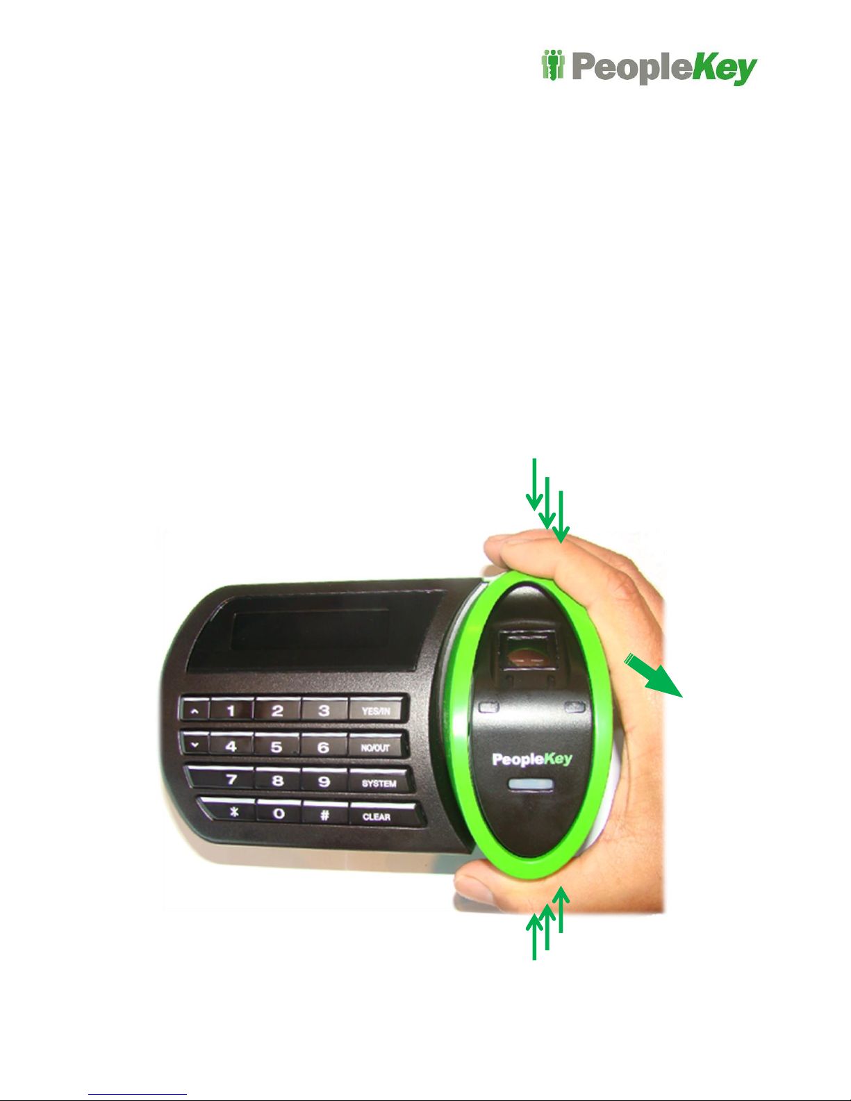
Left and Right handed operation
Please allow for enough clearance all around the V30 Plus Finger Scanner allowing for left and right-
handed users. Consider enough space for bent arms and elbows.
Line of sight to the door
When physical door access is required (the V30 plus Finger Scanner unlocks a door) the V30 Plus
Finger Scanner should at least be in line of site to the door that it is controlling, so as to limit
unauthorised access by tail gating (more than one person entering at the same time).
Avoid collisions/ congestions
Area’s with high traffic usage; where a person scanning will block the flow; should be avoided. Door
openings should not swing into the area colliding with the person operating the V30 plus Finger
Scanner.
Avoid tight passage ways.
Area’s that have trollies, people carrying box’s, pallet or forklift operations, the position and height for
the V30 Plus Finger Scanner should be adjusted to avoid being damaged.
Cable requirements
Networking / interfacing. The V30 plus Finger Scanner location and mounting position will dictate the
communication mode. The V30 plus Finger Scanner connectivity default is via Ethernet –10/100Mbps.
Options include RS485 or RS232, Wiegand, 3G and wireless modem. These options are detailed later
in this manual.
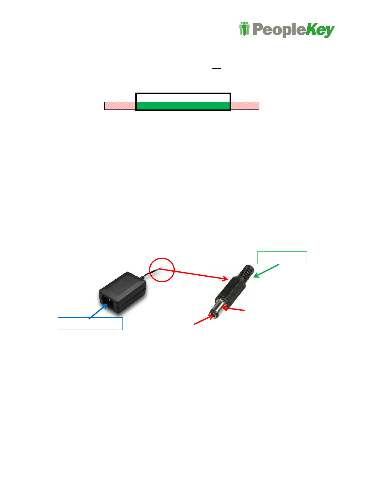
Power cabling, as detailed in the “Power for the scanner” chapter in this manual, the cable run, length
and access require planning prior to installation.
Additional cabling requirements can also include Door strike relay, Door monitor, REX input, Alarm
outputs. The cabling run, length and access require planning prior to installation.
Concrete wall mounting
If the V30 plus Finger Scanner is mounted on a concrete wall, holes should be drilled into the wall and
adequate fastening hardware used depending on the mounting surface. There is a round knockout
located on the bottom of the rear housing if external cable ducting is required.
Environmental conditions.
The V30 plus Finger Scanner position should be positioned taking into consideration the following
environmental conditions:

- 6 -
Operating temperature range: -10oto +50o Celsius.
Not Exposed to water, ingress protection (IP) rating = IP65.
Not exposed to direct sunlight.
Should not be mounted underneath an Air Conditioner drain.
Service requirements.
Cabling lengths should be sufficient to allow the V30 plus Finger Scanner to be removed from the wall
and remain in operation.
To facilitate servicing, the V30 plus Finger Scanner shroud requires removal. Refer to Figure 4.
Sample Installation Pictures

- 7 -
Power and Cable installation
There are normally only two cables (Power and Ethernet) required for a system providing time & attendance
data capture. Refer to Figure 6 for the locations on the rear panel for the connector sockets.
Figure 6: Rear view
Holes for
Mounting
Bracket
12 V DC power connector
Ethernet cable connector
20 pin cable I/O connector

- 8 -
Power for the V30 Plus Finger Scanner unit
The V30 Plus Finger Scanner requires a direct current voltage (DC) supply to operate. The scanner will operate
from +8vDC to +18vDC, ideally a regulated +12vDC supply. Do not connect to AC or Mains power.
Operating input voltage range
There are four external power options:
1. 12Volts DC from a “plug pack” as supplied from PeopleKey.
2. Power Over Ethernet (POE). [Note:- Additional hardware required]
3. 20 way Cable loom.
External DC Power
The 12v DC power pack would normally be plugged into the nearest GPO power outlet. A 12 Volt DC power
pack is supplied by PeopleKey with the V30 plus Finger Scanner - its cable may need to be fed through the wall
or conduit by an electrician. The low power (12VDC) cable provided is approximately 1.5m in length. This can
be lengthened by an electrician as required, or an extension can be purchased (known as a CCD camera power
extension cable at some electrical outlets).
The V30 plus Finger Scanner DC socket input “Tip”is a “Positive” centre.
Power consumption is very low, at less than 120mA per finger scanner when in standby (assuming no other
devices such as door strike mechanisms are powered). Max power during a scan is typically 200mA.
Clients should consider using a UPS (Uninterruptible Power Supplies) where power outages are common. The
same considerations as for other IT equipment in terms of “filtered” or “clean” power and protection against
lighting strikes should also be taken with the V30 Plus Finger Scanner equipment.
Some clients prefer to have their electrician’s mount the power pack in a ceiling, wall or a small plastic box to
hide the 12V power supply or protect it from tampering. Access in the instance of a failure should also be
considered.
<8vDC
+8vDC to +18vDC
>18vDC
+ve Inner ring
GND Outer ring
Mains cable socket
DC Jack/Plug

- 9 -
Power over Ethernet (POE)
The POE feature on PeopleKey V30 Plus Finger Scanners is available as an option in lieu of a 12V power
supply.
A separate POE board is required (Fig 7), it is housed within the V30 Plus Finger Scanners housing. This add-
on will be configured by PeopleKey prior to shipment. All I/O’s will only be available on the plug in 20 pin wiring
cable loom.
Figure 7: V30 Plus back view with POE option
.
Data communications cable
Standard connections (Ethernet)
The data communication cable will need to be a standard 4 pair Cat5e UTP (or better). The termination is a
standard RJ45 plug.
If the V30 Plus Finger Scanner is connected to local area network (LAN) using a router or switch, a
standard Cat5e connection is required.
If the cable from the V30 Plus Finger Scanner plugs directly into a PC (into its network card), a cross-
over Ethernet cable has to be used.
The Cat5e data cable will need to be shielded in instances where the cable will be running near other high
voltage appliances or cables or where RF is a factor.
Ethernet for POE
20 Way I/O Port

- 10 -
The usual preventative measures for surge protection on network cabling applies to V30 Plus Finger Scanners.
Clients are requested to please activate the Ethernet connection (plug the other end of the Ethernet connection
into the network) and test it prior to the scanner installation.
Optional Connection types. (Refer to page 11)
Alternative communication connections are available; the installation position will dictate the required form of
connection.
1
Direct
Scanner to PC
Ethernet with crossover Ethernet cable
2
Network
Scanner to Network
Ethernet to a network switch, standard patch cable.
(90 meters)
3
Serial –RS232
Scanner
For lengths up to 90 meters
4
Serial –RS485
Scanner to RS232/485
convertor
For cable lengths up to 500m
5
Wireless network
Restricted building
access or over roads
Site dependant, typically up to 100 meters, Wireless access
point
6
Wireless internet
Mobile internet
Wireless solutions (3G) as well as a decentralized remote
site solutions (based on internet protocol transfer of V30 Plus
Finger Scanner data) are also available on request.

- 11 -
Server or PC
Network cable (Ethernet Cat 5e)
connected via network switch and
other network equipment to extend
the network over long distances
Wireless link to cross roads
and other site restrictions –
maximum distance
dependent on site, but 100 m
is achievable
Typically 90 m maximum run length
Typically 90 m maximum run
length
Typically 90 m maximum run length
Switch/Router, Other network
equipment to achieve further
network reach
PeopleKey finger
scanner
Server or PC
PC
Server or PC
Crossover Ethernet cable
1: Finger scanner direct to a PC
2: Finger scanner direct to a network
PeopleKey finger
scanner
3: Finger scanner wireless network
Server or PC
PeopleKey finger
scanner
4: Finger scanner wireless communications
PeopleKey finger
scanner

- 12 -
Physical Access Control
Where electronic door locks are to be controlled by the V30 Plus Finger Scanner the door lock wiring is
connected to the back of the V30 Plus Finger Scanner via the 20 way cable harness.
The V30 Plus can power door locking mechanisms that have a Maximum current draw of 150ma @12V. If you
are unsure please contact PeopleKey support for guidance.
Most door locks operate on 12V power, and a single “figure 8” wire pair is sufficient. Where a high voltage; high
power motorized door lock is required, or where other alarm equipment is used to power the door lock,
PeopleKey should be consulted to confirm the wiring requirement. Details for all connection options are listed in
the I/O table later in this manual.
Should customers require the monitoring of doors to report when the door is forced, opened or left ajar,
additional door switch detection wiring is required comprising of another pair of “figure 8” wire, Reed switch or
similar.
Important Note: Refer to the “V30 Plus relay use”guidelines as detailed within
Annex 1 of this document.
Door Relay
outputs
Door relay Normally Open contacts
Door relay Normally Closed contacts
REX
Remote door switch (REX)
Door Monitor
Door monitor input, N/C or N/O
Typically 90 m Maximum run length
Typically 500 m Maximum run length
PeopleKey finger
scanner
PeopleKey finger
scanner
Server or PC
RS232
RS485
RS485 to RS232 convertor
5: Finger scanner Serial, short runs
6: Finger scanner Serial, long runs

- 13 -
Card Readers and other I/O devices
Card readers, Barcode Scanners, PC Kiosks, printers, breathalyzers and many other types of equipment may
be connected to a PeopleKey V30 Plus Finger Scanner. In these applications, special cabling is often required
and PeopleKey should be consulted.
Some clients have their own unique card technology and/or specific card population. These can be external
devices connected to a V30 Plus Finger Scanner. Communications is either via RS232 or Wiegand.
Internal card reader
In high security environments, clients may require a card reader device to be fitted internally in the V30 Plus
Finger Scanner. The card reader potentially adds a second level of security due to the card reader/card security
mechanisms.
PeopleKey provides an optional iClass/Mifare or 125Khz internal card reader, so no additional external wiring is
required. (Figure 8)
Figure 8: V30 Plus with card reader installed internally.
Additional Equipment examples
Bar code reader
PC kiosk
Breathalyzers
Thermal Printer
Swip card reader
These can be external devices connected to a V30 Plus Finger Scanner. Communications is either via serial
(RS232/RS485) or Wiegand in or out.

- 14 -
V30 Plus Web Interface Details
The V30 Plus web interface is a web based server application which displays information presented in a single
function screen. This interface allows interaction and configuration of the V30 Plus unit via a web browser like
Internet Explorer.
It is the responsibility of the client to set up the required security and access policies to allow its users to use the
application from other PC clients.
Figure 9: V30 Plus Web Interface
To access the V30 Plus web interface, enter the IP address of the V30 plus Finger Scanner into a web browser
i.e.:- 192.168.1.2.
If the unit has been configured for DHCP t the IP address may be obtained by running the command prompt
and type in “ping v30-3xxxxx” where “xxxxx” is the serial number of the V30 plus Finger Scanner.
Figure 10: Example of a “Ping”command to a DHCP scanner serial #300070

- 15 -
Outputs and Inputs, Signals and Controls
Wiegand communication
The V30 Plus Finger Scanner supports Wiegand In and Wiegand Out. It can interpret any incoming Wiegand
communications (such as remote Wiegand instructions or External Card Reader Wiegand signals) to control
various security features. Full formatting of the Wiegand word is available.
Wiegand IN
Digital signals from mostly card reader devices, provides the ID number of the user. This is used
instead the ID number entered from a keypad.
Wiegand OUT
A digital signal transmitted by the V30 Plus Finger Scanner to simulate a card reader to communicate to
alarm panels and security access control systems when a user successfully verifies on the V30 Plus
Finger Scanner.
Wiegand Thru
The inputted Wiegand signal is passed through the V30 Plus finger Scanner and is transferred directly
to the Wiegand out signal.
Door Access Control
A relay is fitted (Internal or external) to switch an electric door lock open or closed when a user scans a finger
(direct door access control)
Remote Unlock Module
For high security installations, the V30 plus Finger Scanners support an optional Remote Unlock Module which
can in turn lock/unlock a door. A control signal is used to control the module from the V30 Plus therefore
accessing the wiring of the V30 plus Finger Scanner will not allow a perpetrator to “Short Circuit” the door lock
wiring to gain access.
Timed door access control
This feature allows for specific door access times to be programmed by User ID, time zone or simply barred or
granted. 30 programmable time zones are available. Two zones can be applied simultaneously in one 24 hour
period, and two specific time zones are capable of allowing access only once, subsequently denying further
attempts at access. This functionality can be complimented by any existing door access control system. This
function is programmed within the FingerLan software.
Request to Exit (REX)
This is used to monitor a switch used to override Finger scanning to allow door access to bypass the need to
scan a finger when leaving a building where the V30 plus Finger Scanner is used to control entry access only.
Door monitor
Monitoring and reporting is available for the following situations; door ajar, door forced (breach) and request to
exit (REX).
Communications
Alternative communication connections are available, being serial options of RS232 / RS485

- 16 -
I/O’s signals and controls are only active when enabled through the software configurations.
Function
Terminal
block
Cable Harness
Wire
Pin
Description
Software configuration
DC voltage In
/Out
Right
Red wire
20
8-18vDC
Always present
Right
Black wire
6
GND/Common
Voltage out
Left
Red + White trace
19
+5vDC
Always present
Wiegand Out
Right
Green wire
10
Wiegand Out D0 /Output #7
Full Wiegand protocol is
available
Right
White wire
8
Wiegand Out D1 /Output #8
Left
Blue wire
4
Wiegand Common
Wiegand In
Left
Green + Black
trace
9
Wiegand In D0
Full Wiegand protocol is
available
Left
White + Black
trace
7
Wiegand In D1
Left
Blue wire
1
Wiegand Common
Door relay
Left
Yellow wire
18
Relay common
Right
Yellow + White
trace
16
Door relay N/O
Normally open
Right
Yellow + Black
trace
14
Door relay N/C
Normally closed
REX
Left
Pink wire
5
Remote door entry switch (REX)
Input #3
Door
Monitor
Left
Violet wire
3
Door monitor input
Input #4
Tamper
Right
Orange wire
12
Alarm Out (N/O)
Output #5 (see note)
RS485
Left
Orange + Black
trace
17
RS-485 –Ve (RS232-TX HWV1.0)
Baud rate, Node #
Left
Orange + White
trace
15
RS-485 +Ve
RS232
Left
Grey + Black
trace
13
RS-232 TXD
Baud rate, Node #
Left
Grey + White
trace
11
RS-232 RXD
0volts
Left +
Right
Blue
1
Common wire
Loop
Right
Not used
N/A
Isolated loop terminals.
Important Notice
Note: - Outputs # 5, 7 & 8 - Pulls Low (N/O) for 5-12V @40ma MAX

- 17 -
Wiring cable loom
A cable loom plugged into the rear of the V30 Plus Finger Scanner provides interconnections to the
Input / Output functions and hard wire powering of the unit. The connector has a locating Notch
ensuring its correct insertion.
Figure 11:- Cable loom installed (plugged in) and zoomed inset
Important Notice
The 5vDC Voltage out wire “Red + White trace” will always have +5vDC present. Caution must
be taken as not to short this to any other wires of the cable loom.
Pin
Colour
Function
Function
Colour
Pin
20
Red
8-18vDC In
5vDC Out
Red + White trace
19
18
Yellow
Door Relay Com
RS-485 –Ve
Orange + Black
trace
17
16
Yellow + White
trace
Door Relay N/O
RS-485 +Ve
Orange + White
trace
15
14
Yellow + Black
trace
Door Relay N/C
RS-232 TXD
Grey + Black trace
13
12
Orange
Alarm Out O/C
RS-232 RXD
Grey + White trace
11
10
Green
Wiegand Out D0
Wiegand In D0
Green + Black trace
9
8
White
Wiegand Out D1
Wiegand In D1
White + Black trace
7
6
Black
GND in
Remote Exit
Input (REX)
Pink
5
4
Blue
0v Out
Door monitor
Input
Violet
3
2
Blue
0v Out
0v Out
Blue
1
Red wire –DC voltage in –Pin 20
Blue wire –0v Out –Pin 2

- 18 -
General IT requirements
Only Windows based operating systems are supported in the PeopleKey IT environment.
Clients will need to determine the following information for the connection of each V30 Plus Finger Scanner
A static IP address for the PC / Server (Host IP Address).
A static IP Address must be assigned for each V30 Plus Finger Scanner unit being installed, or
DHCP should be available on the network for the V30 Plus to obtain an IP address automatically. It
is important that the units “IP Address”is not used by any other device.
Gateway and subnet information.
Resolve any Firewall and Anti-virus related issues
PeopleKey continuously bench test all applications when new PC operating and Server systems are released.
Please contact PeopleKey Support when PC/Server system upgrade or migration is planned.
Hardware resources
Server resource use is minimal with FingerLan; it can often run on a desktop PC and even note-books
depending on the number of V30 Plus Finger Scanners supported. Disc space for the requisite software is
often below 150 Mb and space for data growth of 100 Mb per year is often sufficient depending on the number
of users, activity rate and IT data management policies.
In terms of memory overhead (RAM) a PC or server with 4GB of memory will be adequate for small numbers of
installed V30 plus Finger Scanners. Still it should be checked if the server has enough processing power
(memory free and processing power free) to enable PeopleKey applications to run.
Functions / Operation
The V30 Plus web interface can be used to perform configuration parameter changes of the V30 plus Finger
Scanner; FingerLan is used to manage users, user groups, access control and user administrative levels.
If 3rd party software is used to access the FingerLan data, the FingerLan server or PC hard drive will have to be
networked and mapped for this purpose.
If the clocked times and related data are to be used frequently, the V30 plus Finger Scanners are required to be
on-line permanently. A Windows based PC or Server permanently on line is strongly recommended to run the
Fingerlan software.
V30 plus Finger Scanners can collect data in “off-line mode” but the risk of data loss (in the unlikely but possible
event of hardware failure) is limited if distributed and duplicated on a live server.
Verification time and date data is sent via Ethernet to the Fingerlan software and stored in a Microsoft Access or
SQL Database. The software runs two services on the host server, enabling data collection from V30 Plus
Finger Scanners live, whether the FingerLan software user interface is opened or not.
Additional reporting / query software such as WorkForce Clarity is available from PeopleKey and can reside on
client PCs, utilizing ODBC connectivity to access the database file on the server.
Other manuals for V30 Plus
1
Table of contents