Instruction Manual
1. Marking
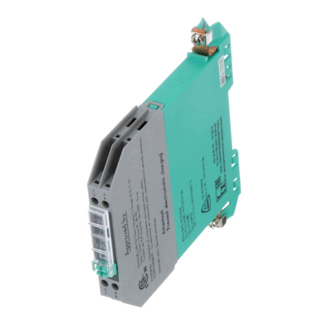
Fieldbus Segment Protector
F2-SP-IC*
ATEX certificate: TÜV 13 ATEX 107689 X
ATEX marking:
1 II 3G Ex nA [ic] IIC T4 Gc ,
1 II 2(3)D Ex tb [ic Dc] IIIC T130°C Db
IECEx certificate: IECEx TUN 13.0004X
IECEx marking:
Ex nA [ic] IIC T4 Gc ,
Ex tb [ic Dc] IIIC T130°C Db
CCC certificate: 2020322310002785
CCC marking: Ex ec [ic] IIC T4 Gc, Ex tb [ic Dc] IIIC T130°C Db
The *-marked letters of the type code are placeholders for versions of the
device.
Pepperl+Fuchs Group
Lilienthalstraße 200, 68307 Mannheim, Germany
Internet: www.pepperl-fuchs.com
2. Target Group, Personnel
Responsibility for planning, assembly, commissioning, operation,
maintenance, and dismounting lies with the plant operator.
The personnel must be appropriately trained and qualified in order to carry
out mounting, installation, commissioning, operation, maintenance, and
dismounting of the device. The trained and qualified personnel must have
read and understood the instruction manual.
Prior to using the product make yourself familiar with it. Read the
instruction manual carefully.
3. Reference to Further Documentation
Observe directives, standards, and national laws applicable
to the intended use and the operating location.
Observe Directive 1999/92/EC in relation to hazardous areas.
The corresponding datasheets, manuals, declarations of conformity, EU-
type examination certificates, certificates, and control drawings if
applicable supplement this document. You can find this information under
www.pepperl-fuchs.com.
For specific device information such as the year of construction,
scan the QR code on the device. As an alternative, enter the serial number
in the serial number search at www.pepperl-fuchs.com.
Due to constant revisions, documentation is subject to permanent change.
Please refer only to the most up-to-date version, which can be found under
www.pepperl-fuchs.com.
4. Intended Use
The Segment Protector is a fieldbus device coupler designed in
accordance with IEC/EN 61158‑2 to connect field devices via spurs to the
trunk of a segment.
Each spur individually limits or isolates the current during a spur failure,
ensuring that the remaining segment is not affected.
The device is designed for wall mounting.
Use mounting materials that fit the nature of the mounting surface.
Use mounting materials which are suitable to secure the device safely.
If the device has already been operated in general electrical installations,
the device may subsequently no longer be installed in electrical
installations used in combination with hazardous areas.
The device is designed for use in intrinsically safe fieldbus systems
according to FISCO or Entity.
The device must only be operated in the specified ambient temperature
range and at the specified relative humidity without condensation.
5. Improper Use
Protection of the personnel and the plant is not ensured if the device
is not used according to its intended use.
6. Mounting and Installation
Prior to mounting, installation, and commissioning of the device you
should make yourself familiar with the device and carefully read the
instruction manual.
Observe the installation instructions according to IEC/EN 60079-14.
Observe the installation instructions according to IEC/EN 60079-25.
Do not mount a damaged or polluted device.
If the device has already been operated in general electrical installations,
the device may subsequently no longer be installed in electrical
installations used in combination with hazardous areas.
To ensure the degree of protection:
lThe housing must not be damaged, distorted or corroded.
lAll seals must be undamaged and correctly fitted.
lAll screws of the housing/housing cover must be tightened with the
appropriate torque.
lAll cable glands must be suitably sized for the incoming cable
diameters.
lAll cable glands must be tightened with the appropriate torque.
lAll unused cable glands must be sealed and closed with appropriate
sealing plugs or stopping plugs.
The device may be installed in a corrosive atmosphere according to ISA-
S71.04, severity level G3.
Do not connect the signal lines to earth or to the cable shield.
All cables and connection lines must be mechanically secured.
Observe the tightening torque of the screws.
6.1. Requirements for Cables and Connection Lines
Observe the permissible core cross section of the conductor.
The insulation stripping length must be considered.
When using stranded conductors, crimp wire end ferrules
on the conductor ends.
6.2. Hazardous Area
Ensure that the trunk is equipped with two terminators, one at each end of
the trunk.
Ensure that the operating element for gas group selection is set to the
correct position for your intended application.
Connection or disconnection of energized non-intrinsically safe circuits is
only permitted in the absence of a potentially explosive atmosphere.
Only plug and pull the plug-in jumpers in the absence of a potentially
explosive atmosphere.
6.2.1. Type of Protection
6.2.1.1. Type of Protection Ex i
Observe the compliance of the separation distances between two
adjacent intrinsically safe circuits according to IEC/EN 60079-14.
Intrinsically safe circuits of associated apparatus (installed in non-
hazardous area) can be led into hazardous areas. Observe the
compliance of the separation distances to all non-intrinsically safe circuits
according to IEC/EN 60079-14.
If circuits with type of protection Ex ic are operated with non-intrinsically
safe circuits, they must no longer be used as circuits with type of
protection Ex ic.
Observe the respective peak values of the field device and the associated
apparatus with regard to explosion protection when connecting intrinsically
safe field devices with intrinsically safe circuits of associated apparatus
(verification of intrinsic safety). Also observe IEC/EN 60079-14 and
IEC/EN 60079-25.
6.2.2. Dust
6.2.2.1. Zone 22
A device with external connectors for non-intrinsically safe circuits must
not be installed in Zone 22.
Connection or disconnection of energized non-intrinsically safe circuits is
only permitted in the absence of a potentially explosive atmosphere.
When energized, only open the housing in the absence of a potentially
explosive dust atmosphere.
Remove the dust before opening the housing.
6.2.2.2. Zone 21
A device with external connectors must not be installed in Zone 21.
Connection or disconnection of energized circuits is only permitted in the
absence of a potentially explosive atmosphere.
Circuits with type of protection Ex ic meet equipment protection level Dc
only.
The housing must not be opened when the device is energized.
Remove the dust before opening the housing.
7. Operation, Maintenance, Repair
Prior to using the product make yourself familiar with it. Read the
instruction manual carefully.
Do not repair, modify, or manipulate the device.
If there is a defect, always replace the device with an original device.
7.1. Device-Related Information
Only manipulate the connections within the specified ambient temperature
range.
Temperature range -5 °C to +70 °C
8. Delivery, Transport, Disposal
Check the packaging and contents for damage.
Check if you have received every item and if the items received are the
ones you ordered.
DOCT-3983A / 2023-07 1 / 2


