Performax 24220 User manual

SMART GARAGE DOOR
OPENER USER MANUAL
MODEL #24220
SKU: 425-1673
Customer service: 1.877.436.4402
REV 7/2020

TABLE OF CONTENTS
Congratulations on purchasing your Performax
smart garage door opener. It will provide you with
many years of security, safety and convenience. This
installation and owner’s manual contains complete
instructions for installing and operating your garage
door opener.
To register your opener, go to:
www.performaxopeners.com
Carton Contents............................................1
Before You Begin / Safety Instructions................ 2
Preparation / Tools Needed ............................ 3
Rail Assembly .............................................. 4
Rail and Power Head Assembly ........................ 5
Trolley and Pulley Assembly............................. 6
Installing Chain and Cable ........................... 7-8
Attaching Sprocket Cover ............................... 9
Mounting Header Bracket.............................. 10
Attaching Rail and Mounting Door Bracket ......... 11
Mounting Power Head to Ceiling ..................... 12
Attaching Door Arms.................................... 13
Installing Emergency Release Handle................ 14
Connecting Photo Eye Safety System ................ 15
Connecting Power and Aligning Photo
Eye Safety System........................................ 16
Before We Start Programming The Opener ........ 17
Travel Limit Adjustment – UP Limit .................... 18
Travel Limit Adjustment – DOWN Limit............... 19
Setting the Force ........................................ 20
Final Adjustments and Testing ......................... 21
Connecting Deluxe Door Control.................... 22
Programming Handheld Remote .................... 23
Enabling/Disabling
Motion Activated Security Lighting.................. 24
Installing the Smart Garage Door Controller....... 25
Using your Garage Door Opener ................26-30
Troubleshooting..................................... 31-32
Maintenance ............................................. 33
Warranty ..............................................34-35
Spare Parts ............................................... 36
Opener Assembly Parts................................ 37

performaxopeners.com Customer Service: 1-877-436-4402 1
CARTON CONTENTS
Rail Trolley Pulley 1 x Master Link
Emergency
Release Handle
5 x Clevis Pins
2 x 5/16" x 1"
5 x Clevis Pins
2 x 5/16" x 1-3/8"
5 x Clevis Pins
1 x 3/8" x 1-3/4"
5 x Hitch Pins 7 x Flange Nut
2 x Self-Threading
Screws
1/4" x 5/8"
Three Button
Remote
Deluxe
Door Control
6 x Lag Screws
5/16" – 1/1/2"
4 x Screws
#12 x 1-1/4"
1 x Self-Threading
Screw
#8-18 x 5/16"
Power Head
Photo Eye
Safety System
Header Bracket
Door Bracket
Door Arms
Sprocket Cover
Hanging Bracket
Trolley Sha/
Chain Assembly
Note: hardware shown is not to scale.
6 x Screws
#6 x 1-3/8"
6 x Bolts
5/16"– 18 x 1" 6 x Anchors
Insulated Staples Controller
Wireless Door
Sensor

2performaxopeners.com Customer Service: 1-877-436-4402
BEFORE YOU BEGIN SAFETY INSTRUCTIONS
To reduce the risk of severe injury or death:
1. READ AND FOLLOW ALL INSTALLATION INSTRUCTIONS.
2. Install only on a properly balanced garage door. An improperly balanced door has the
potential to inflict severe injury. Have a qualified garage door service technician make
repairs to cables, spring assemblies, and other hardware before installing the opener.
3. Remove all ropes and remove or make inoperative all locks connected to the garage
door before installing opener.
4. Where possible, install the opener no more than 12" above the height of the closed door.
For products having an emergency release, mount the emergency release within reach, but
at least 6 feet above the floor and avoiding contact with vehicles to avoid accidental release.
5. Do not connect the opener to source of power until instructed to do so.
6. Install the door control button: (a) within sight of door, (b) at a minimum height of 5 feet
so small children are not able to reach it, and (c) away from all moving parts of the door.
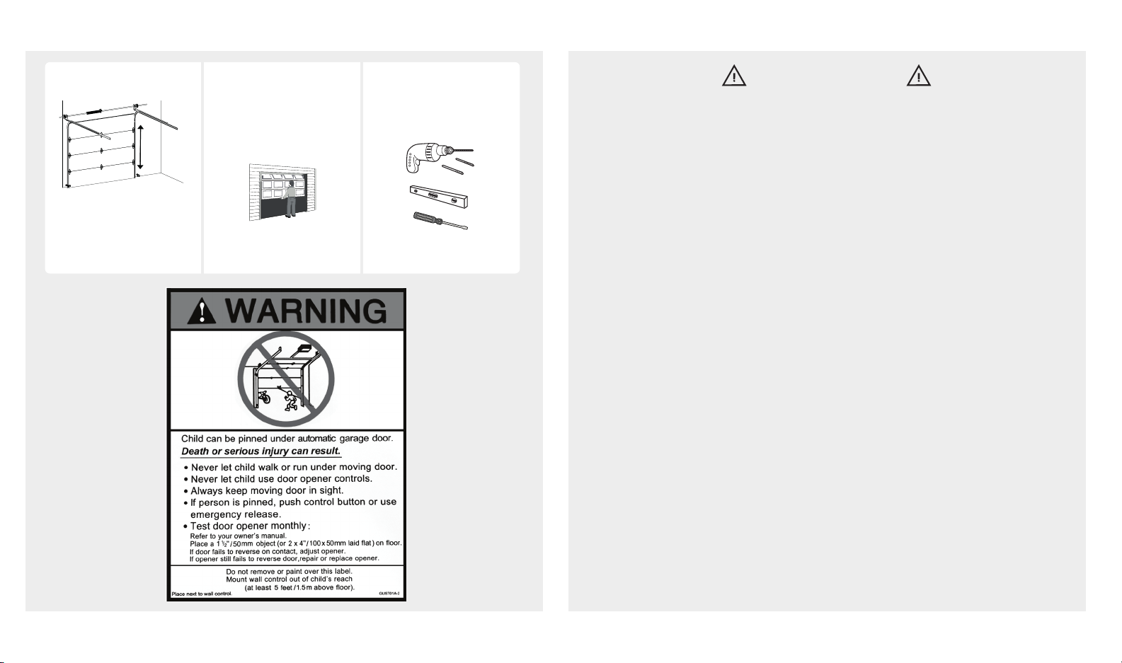
7. Install the Entrapment Warning Label (shown in the
Before You Begin
section) next to
the wall-mount control button in a prominent location.
8. Aer installing the opener, the door must reverse when it contacts a 1-1/2 inch (3.8 cm)
high object (or a 2x4 board) laid flat on the floor.
9. NEVER try to remove, loosen, move, or adjust garage door, cables, pulleys, brackets,
and door springs. All are under EXTREME tension.
10. To reduce the risk of injuries to persons – use this operator only with residential sectional
garage doors. Only enable the unattended operation feature when installed with a
sectional door.
11. The Smart Door Controller should be used only on sectional doors and with garage door
openers made aer 1993 with a photo eye safety system.
WARNING
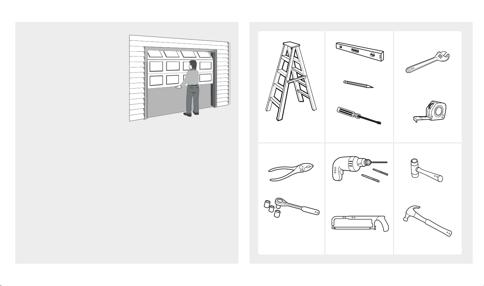
Measure door height. Check mounting
locations. Are additional
reinforcement
materials needed?
If over 7.5 feet (2.28 m), rail
extension kit will be needed.
(8 . or 10 . extension kits
available if needed.) See page 3
Entrapment
Warning Label
See page 3
Check your toolbox.
Do you have all the
tools needed?
7.5 feet
(2.28 m)

performaxopeners.com Customer Service: 1-877-436-4402 3
PREPARE GARAGE DOOR FOR INSTALLATION TOOLS NEEDED
Step Ladder
Ratchet with
1/4", 7/16" and
1/2" sockets
Level
Pencil
Screwdriver
Hack Saw
Tape Measure
Adjustable Wrench
Rubber MalletDrill, 3/16" and
5/16" Drill Bits
Pliers
Hammer
DO NOT RE-USE PARTS
AND WIRING FROM AN
OLD OPENER. YOUR NEW
PERFORMAX OPENER WILL
NOT WORK IF OLD PARTS AND
WIRING ARE USED. THIS WILL
ALSO VOID THE WARRANTY.
BEFORE beginning installation:
1. Disable locks and disengage
trolley from current opener.
2. Perform the following door test to ensure your door is balanced and in
good working condition.
Make sure garage door is fully closed before you start the installation
To test your garage door:
1. Raise and lower the door to check if there is any sticking or binding.
2. Check for loose hinges, damaged rollers, frayed cables and damaged or
broken springs.
3. Li the door approximately halfway and release. The door should stay at
that point under proper spring tension.
Call a qualified garage door service technician if your door binds, sticks or
is unbalanced.
Note: tools shown are not included.

4performaxopeners.com Customer Service: 1-877-436-4402
RAIL ASSEMBLY
Look in the box for:
Rubber Mallet
Rail – Middle Segments x3
Rail – End Segment
Tools needed:
Connect rails starting with the rail header segment. To apply additional force tap gently on the end of the
connected rail segments with a rubber mallet or on padded flooring.
Rail – Header Segment Securely connected by applying force
CAUTION
To prevent INJURY from pinching, keep hands and fingers
away from joints when assembling the rail.
Rail- Header
Segment
Rail- Middle
Segment
Rail- Header
Segment
Rail- Middle Segments x3
Rail- End Segment
Stop Bolt
Loosely connected
Right
Wrong

performaxopeners.com Customer Service: 1-877-436-4402 5
RAIL AND POWER HEAD ASSEMBLY
Look in the box for:
Power Head
Opener Carton
Clevis Pin
5/16" x 1-3/8"
Hitch Pin
Insert rail-end segment into
bracket as shown.
Insert clevis pin into rail
bracket as shown.
Insert hitch pin into clevis pin
as shown.
Use garage door opener carton to assemble rail to power head. Use packing material as protective base for
power head.
Rail Bracket
Carton
Protective base

6performaxopeners.com Customer Service: 1-877-436-4402
Clevis Pin
3/8" x 1-3/4"
Hitch Pin
Insert clevis pin through rail
hole and pulley.
Insert hitch pin into clevis pin.
TROLLEY AND PULLEY ASSEMBLY
Look in the box for:
Trolley
Pulley
Slide trolley onto the rail. Make sure the arrow on the trolley points toward the door.
Insert pulley into the pulley slot.

performaxopeners.com Customer Service: 1-877-436-4402 7
INSTALLING CABLE AND CHAIN
Look in the box for:
Trolley Sha/Chain Assembly
Master Link
WARNING
To prevent SERIOUS INJURY:
• DO NOT connect power until instructed.
• Keep hands and fingers clear from sprocket during
operation.
• Wear gloves when installing chain and cable.
• Keep hands and fingers away from joints and
possible sharp edges.
Insert cable through circular hole in trolley. Pull
cable through pulley slot and toward power head.
Chassis
Pull chain with box along the right side of the rail
towards trolley and then remove box.
7"
(17.8 cm)
Loosely attach trolley sha with chain connector. 5 complete turns will be sufficient.
Pull trolley lock lever down to unlock. Insert trolley
sha through the trolley and pull lever back up.
End of
Chain
Trolley in
engaged
position
Align end of chain around sprocket and extend chain
past the le side of the chassis, approximately 7" (17.8
cm). Sprocket teeth must engage the chain.

8performaxopeners.com Customer Service: 1-877-436-4402
INSTALLING CABLE AND CHAIN
Bring cable and chain together and connect with master link. Check to make sure the chain is not twisted. If
chain and cable are not close enough to connect with master link, loosen chain-to-cable connector to create
more slack.
WARNING
To prevent SERIOUS INJURY:
• DO NOT connect power until instructed.
• Keep hands and fingers clear from sprocket during
operation.
• Wear gloves when installing chain and cable.
• Keep hands and fingers away from joints and
possible sharp edges.
Adjust chain tension by turning chain-to-cable connector until chain is about 1/4 inch (.64cm) above the base of
rail. Once proper tension is achieved tighten lock nut against chain-to-cable connector.
Chain-to-cable connector
Tighten until...
1/4 inch
(.64 cm)
Nut

performaxopeners.com Customer Service: 1-877-436-4402 9
ATTACHING SPROCKET COVER
Look in the box for:
Sprocket Cover
Front
Tab
Rear Tab
Self-Threading Screw
#8-18 x 5/16
Flange Nut
Attach sprocket cover to
power head.
Fasten rear tab with flange nut
on top of steel chassis.
Fasten front tab with self-
threading screws to hole on
top of rail bracket.

10 performaxopeners.com Customer Service: 1-877-436-4402
MOUNTING HEADER BRACKET
Look in the box for:
Mark the center line above the door with a pencil. Open door to the highest point of travel.
Header Bracket 2 x Lag Screws
5/16" x 1-1/2"
To prevent SERIOUS INJURY:
• DO NOT connect power until instructed.
• The header bracket MUST be SECURELY fastened
to the structural support on the mounting wall or
ceiling, otherwise garage door opener may not
reverse when required. DO NOT install the header
bracket into drywall. If installing onto drywall
surface either cut out drywall or install board over
drywall to secure.
• Concrete anchors MUST be used when mounting
the header bracket into masonry.
• NEVER try to loosen, move or adjust garage door
springs, cables, pulleys, brackets, or hardware.
• Contact a qualified garage door service technician
if your door binds, sticks or is unbalanced. An
unbalanced door might not reverse when required.
Center Line
2-1/4 inch
(5.7cm)
2-1/4 inch
(5.7cm)
WARNING
Highest Point
of Travel
Take a level, measure and mark highest point of the
door on the wall. Raise level to clear torsion bar if
required, then mark highest point.
Measure 2-1/4 inch (5.7 cm) above the highest
point mark. While placing the bottom of the header
bracket on this mark, mark the desired mounting
holes in the header bracket. Drill two holes and
fasten header bracket using screws.

performaxopeners.com Customer Service: 1-877-436-4402 11
ATTACHING RAIL AND MOUNTING DOOR BRACKET
Look in the box for:
Use garage door opener carton to support power
head. Rail header segment end should be pointing
to header bracket.
Align header rail hole to header bracket hole.
Connect header rail and header bracket with clevis
pin and secure with hitch pin.
Hitch Pin Clevis Pin
5/16" x 1-3/8"
Door Bracket 2 x Self-Threading
Screws - 1/4" x 5/8"
To prevent SERIOUS INJURY:
• DO NOT connect power until instructed.
• REINFORCEMENT is recommended for fiberglass,
aluminum or lightweight steel garage doors
BEFORE installing the door bracket. Contact your
door manufacturer for reinforcement options.
Header
Bracket Hole
Header
Rail Hole
Carton
Door Edge
2" - 4" (5 - 10 cm)
CAUTION
Position door bracket on centerline of the top
garage door panel. Door bracket should be 2-4
inches (5-10 cm) below the top edge of door panel.
Attach door bracket to steel door support using the
two self-threading screws.
Wood door: mark and drill two 5/16" holes through the
garage door. Secure the door bracket using two 5/16"
carriage bolts, washers and nuts (not provided). Length of
bolts will depend on thickness of your door.

12 performaxopeners.com Customer Service: 1-877-436-4402
MOUNTING POWER HEAD TO CEILING
Look in the box for: Li power head onto ladder. Position and
align power head with rail assembly to
centerline. Fully open door manually and
place a 2x4 between the rail and the door.*
Angle Iron
(not included)
Finished Ceiling Finished Ceiling Unfinished Ceiling
Structural
Support
Open
WARNING
To prevent SERIOUS INJURY:
• DO NOT connect power until instructed.
• Install motor height so the rail is level from the
motor head to the wall
• Fasten the opener SECURELY to STRUCTURAL
SUPPORT of the garage to prevent falling.
• If installing brackets to masonry, concrete anchors
(not provided) MUST be used.
• To prevent damage to garage door surface, rest
garage door opener rail on 2x4 placed on top
section of door.
4 x Lag Screws
5/16"-18 x 1"
4 x Bolts
5/16" - 18 x 1"
4 x Flange Nut Hanging Brackets
Use lag screws to attach angle
iron to the structural supports
before installing the garage
door opener onto a finished
ceiling. Measure the distance
from each side of the power
head to the angel iron.
Cut both hanging brackets to
appropriate length. Attach the
end of each hanging bracket
to the angle iron with 5/16" x
1" bolts and flange nuts.
Attach power head to hanging
brackets with 5/16" x 1" bolts and
flange nuts. Place level on rail; opener
should be level. Remove 2x4 and
manually close the door. If the door
hits the rail, either raise the head onto
the hanging brackets or if necessary
raise the header bracket.
Three most common installation options. Determine the mounting
option that works best for you.
*A 2x4 is ideal for setting the distance between the rail and the door at the highest point of door travel.
2x4

performaxopeners.com Customer Service: 1-877-436-4402 13
ATTACHING DOOR ARMS
Look in the box for:
3"
(7.6 cm)
8" (20.3 cm)
Curved Door Arm Straight Door Arm
2 x Hitch Pins 2 x Clevis Pins
5/16" x 1"
2 x Bolts
5/16" - 18 x 1"
2 x Flange Nuts
To prevent SERIOUS INJURY:
• DO NOT connect power until instructed.
• Keep hands and fingers away from the sprocket
during operation.
• Wear gloves when installing chain/belt and cable.
• Keep hands and fingers away from joints and
possible sharp edges.
Close your garage door and
disengage trolley. Fasten
curved door arm to the door
bracket with 5/16" x 1" clevis
pin and secure with hitch pin.
Fasten straight door arm to
trolley with a 5/16" x 1" clevis
pin and secure with hitch pin.
Attach door arms with two
5/16" bolts and flange nuts.
Bring straight and curved door
arm together. Find two pairs
of holes that line up and join
sections with two 5/16" bolts
and flange nuts. Select holes as
far apart as possible to increase
door arm rigidity.
WARNING
2"- 4"

14 performaxopeners.com Customer Service: 1-877-436-4402
INSTALLING EMERGENCY RELEASE HANDLE
Look in the box for:
Emergency Release Handle
To prevent SERIOUS INJURY:
• In case of power outage or door obstruction, PULL
EMERGENCY HANDLE to release door from opener.
• When trolley is disengaged, (trolley lever pointing
down) door can be operated manually.
• To engage, flip the trolley lever up so it is horizontal.
Trolley will automatically re-engage when garage
door opener is activated.
• DO NOT use emergency handle to pull the door
open or close.
WARNING
* VERY IMPORTANT! *
Emergency release handle must clear all vehicles. An emergency release handle set too low may get caught
by the vehicle and cause damage to the opener. Measure from the floor to the top of your vehicle and set the
emergency release handle above this measurement.
Thread end of rope through handle and secure with
an over hand knot. Thread end of the rope through
hole in trolley lever.
Measure rope length so the handle is 6 feet
(183 cm) above the floor and is clear from the top of
your vehicle. Secure with a overhand knot.
Hole in
Trolley
Lever

performaxopeners.com Customer Service: 1-877-436-4402 15
Photos eyes
should be no
more than 6
inches (15.2 cm)
above the floor.
CONNECTING PHOTO EYE SAFETY SYSTEM
Look in the box for:
Mount photo eyes using #12 x 1-1/4" screws provided. Run wire to power head. Use insulated staples
to secure photo eye wires to wall and ceiling.
Take care not to puncture the wires while
securing staples.
Cut and discard excess wire. Use small flat head screwdriver to
push in grey tab on the terminal block located on the rear panel
of the power head. Insert 1/2 inch (1.2 cm) of the wire into the
terminal while pushing in the tab.
* VERY IMPORTANT! *
Strip 7/16 inch (1 cm) of insulation
from the end of the wire.
Each pair of terminals MUST be
connected with one white wire and
one striped wire (non-polarized) from
the SAME photo eye.
Floor mounting
(concrete anchors
not provided)
To prevent SERIOUS INJURY or DEATH from
electrocution:
• Power MUST NOT be connected until instructed.
• The garage door opener will not operate until the
photo eye safety system is properly connected and
aligned.
• Install the photo eye safety system NO higher than
6 inches (15 cm) above the floor.
• No part of garage door or other objects should
obstruct the photo eye safety system during door-
closing.
4 x Screws
#12 x 1-1/4"
7/16 inch
(1 cm)
Alternative mounting location:
Door track / wall mounting. Photo
eyes should be no more that 6
inches (15.2 cm) above the floor.
Insulated Staples
Photo Eyes
WARNING

16 performaxopeners.com Customer Service: 1-877-436-4402
CONNECTING POWER AND ALIGNING PHOTO EYE SAFETY SYSTEM
* DO NOT OPERATE OPENER AT THIS TIME *
Plug power head into a grounded outlet ONLY. If there is no
grounded outlet present, call a qualified electrician to replace
the outlet. Use of a surge protector is highly recommended.
Invisible
Light Beam
Aligned
To prevent SERIOUS INJURY or DEATH from
electrocution or fire:
• Power MUST be DISCONNECTED BEFORE
proceeding with permanent wiring procedures.
• Garage door opener installation and wiring MUST
be in compliance with all local electrical and
building codes. Make sure the opener is ALWAYS
grounded.
• NEVER use an extension cord, 2-wire adapter or
modify the power plug in any way to make it fit the
outlet.
To prevent SERIOUS INJURY or DEATH from a closing
garage door:
• The photo eye safety system MUST be installed
BEFORE connecting power.
• The photo eye safety system MUST be properly
connected and aligned BEFORE operating the
opener.
NOTICE:
The garage door opener cannot be programmed
and will not close the door until photo eye safety
system are installed and aligned.
Using the wing nut located on
the photo eyes, adjust alignment.
When the photo eye safety system
is properly aligned the green LED
(emitter) will emit a steady green
light and the red LED (sensor) will
emit a steady red light. The path of
the invisible light beam MUST NOT be obstructed. No part
of the garage door or any hardware should interfere or block
either sensor.
The emitter generates the invisible light
beam, and the sensor receives the invisible
light beam.
Right
For Permanent Wiring ONLY
Wrong
Steady Red &
Green LED
Conduit with wire
Line (Black)
Neutral (White)
White
Black
(From Transformer)
Ground (Green/Yellow)
Ground Screw (Green)
Brown
Wire nut
Emitter
Green LED ON
Sensor
Red LED ON
WARNING
Green LED (emitter) will flash until it is aligned
with red LED (sensor). Red LED will not
illuminate until it is aligned with green LED.

BEFORE WE START PROGRAMMING THE OPENER
performaxopeners.com Customer Service: 1-877-436-4402 17
Before programming the garage door opener please ensure the following steps are completed:
1. Door is fully closed. 2. Photo eyes are aligned.
Aligned
Steady Red &
Green LED
Emitter
Green LED ON
Sensor
Red LED ON
To engage trolley sha with trolley, open or close
the garage door by hand until the trolley engages
with a click.
Flip lever on trolley so it is in engage
position (horizontal and pointing at the opener)
Trolley in engaged position
Trolley Sha
When the door is closed, the leading edge of the
trolley should not be closer than 8" to the center
(pin) of the pulley.
3. Trolley sha is engaged with trolley.

18 performaxopeners.com Customer Service: 1-877-436-4402
TRAVEL LIMIT ADJUSTMENT - UP LIMIT
With door in the closed position, press and release “Limit” button, the green (UP) LED will illuminate.
Press and hold the “Up” button while the "Up" light is illuminated until door reaches desired open position.
If needed, press the down or up arrow to micro-adjust .
Press and release
LIMIT just once
Press and release LIMIT just once
To prevent SERIOUS INJURY or DEATH from
improper Force Adjustment:
• YOU CANNOT adjust force manually to compensate
for binding or sticking of the garage door. Call
a qualified garage door service person to make
necessary adjustments in case of binding.
• YOU CANNOT manually increase the force required
for closing the door.
• Aer ANY adjustments, Safety Reversal Test MUST
be performed to ensure the door reverses on contact
with a 1-1/2 inch (3.8 cm) high object (2x4 laid flat).
Press and hold UP
* DO NOT HIT STOP BOLT *
There should be a minimum 2 inch (5 cm) gap
between trolley and stop bolt.
Once the door is at the desired open position,
press and release the “Limit” button once. The
“OK” LED flashes and turns off. The UP Limit has
now been set.
Minimum 2 inch (5 cm) gap
Stop BoltTrolley
NOTICE:
Travel limits and auto force setting must be set for
the opener to work. All steps on pages 18-20 must
be followed.
WARNING
Desired
UP limit
This manual suits for next models
1
Table of contents
Other Performax Garage Door Opener manuals
Popular Garage Door Opener manuals by other brands

Genie
Genie Series GCG manual

Wisniowski
Wisniowski UNITHERM SSp Assembly and operating instructions

Chamberlain
Chamberlain LiftMaster 50-WSE-14 manual

Merlin
Merlin Commander Extreme MS125MYQ Installation and operating instructions

Vimar
Vimar Elvox EF01.1 Installation and operation manual

Craftsman
Craftsman 39535006 owner's manual

Superlift
Superlift SDO-3DC Installation instructions and user guide

CAME
CAME AMICO-S24 Quick setup guide

Chamberlain
Chamberlain LiftMaster 335LM Security+ owner's manual

Chamberlain
Chamberlain C610C owner's manual

Erreka
Erreka RINO installation guide

Cardin Elettronica
Cardin Elettronica 310/GLB242SWS instruction manual