Performax GTC2DP User manual

1 of 6
Assembly Instructions
GARAGE STORAGE SOLUTIONS
TALL CABINET
Model: GTC2DP
SKU: 211-4354 Safety Instructions
- Use caution when handling and assembling metal parts. The metal may have sharp edges or corners.
The use of protective gloves is recommended.
- This unit should be securely anchored to a wall with suitable fasteners (stud fastener included).
- DO NOT use this unit for anything that is outside the designed function of storage.
- DO NOT step or stand on the shelves.
- The maximum evenly distributed weight for each shelf is 100 lbs.
General Instructions
It is recommended that the cabinet be assembled by more than one person. During shipping and handling, some
of the tabs that are used for assembly may have closed together. Use a flat tipped screwdriver to either pry up or
push from behind the tab to re-open. To assure the squareness of the unit, do not fully tighten the nuts and screws
used in the assembly until all are in place.After all nuts and screws are in place, square the unit on a level surface
and tighten all nuts and screws appropriately.
Parts List & Product Specification
Tools Required
-Rubber Mallet
-Small Blade Screwdriver
-Philips Head Screwdriver
ASSEMBLY QUESTIONS: PLEASE CALL TOLL FREE (866) 441-5080
Ref#
Description
QTY
Ref#
Description
QTY
A
Right Hand Back
1
H
Left Hand Door
1
B
Left Hand Back
1
I
Right Hand Door
1
C
Right Hand Side
1
J
Bolt,M6*10
10
D
Left Hand Side
1
K
Nut,M6
10
E
Top
1
L
Leg leveler
4
F
Bottom
1
M
Screw
1
G
Shelves
3
N
Washer (stud attachment)
1

2 of 6
Assembly Instructions:
Getting Started
Unpack all parts and layout on packing material. Visually inspect the corners. These are the most susceptible to
minor variation through the shipping and handling process. If you find a corner bent out of place, use you hand and
gently move the corner back to the designed shape.Also during shipping and handling some of the tabs used for
engaging the panels together may have become closed. Visually inspect all panels and if found that some are
closed, use a small blade screwdriver to push the tabs from behind to open slightly. (it is recommended to push
tabs out slightly for ease of assembly, and then tap back down with a rubber mallet, to tighten engagement).An
example of pushing the tabs out and how the engagement process works is shown below:
Push tab slightly from
back side to open
Small blade screwdriver
Piece with tab
goes under piece
with rectangular
hole Side part
Side part
Tab fully engaged
Tap tab with rubber
mallet to tighten
engagement

3 of 6
Step 1 - Back Assembly
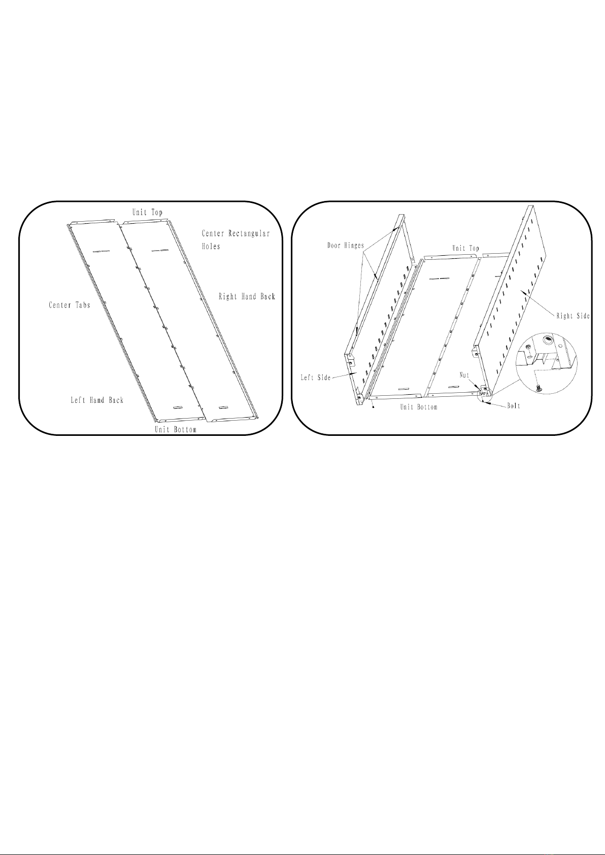
Place the left and right hand backs on a level surface (flange sides facing up; Figure 1). Use packing material to
protect the finish. Place the panel with the center tabs (left hand back) under the panel with the center rectangular
holes (right hand back). Make sure the tabs ride into the rectangular holes and slide the backs together. Check to
make certain that all the tabs and rectangular holes have engaged completely and that the screw holes on the
back panel have properly aligned. Use a small tipped screwdriver to assist in aligning the screw holes if necessary.
Figure 1 –Back Assembly Figure 2- Side Assembly
Step 2 - Side Assembly
Identify the right side panel and the left side panel by taking one of the panels and place the tabs facing up. Use a
small blade screwdriver to push tabs out slightly. Place the corresponding side panel under the back assembly
making sure the tabs of the side panel ride into the rectangular holes of the back assembly. Slide the parts together
making sure that the tabs and rectangular holes fully engage (properly completed, the side and back assembly will
be even at both ends). After assuring the correct side is fastened to the back assembly and the tab engagements
are complete, tap tabs down with a rubber mallet to tighten the engagement. Repeat the same process for the
opposite side panel. Finish attaching sides to back panel by using two M6*10 bolts and M6 nuts, these are located
at the bottom (ref Fig 2).
Step 3 –Bottom Assembly
Use a small blade screwdriver to push tabs out slightly. Holding the bottom from the large side (front), place the
bottom onto the inside of the back and side assembly. The rear part of the bottom will slide down onto four (4) tabs
located on the back assembly. Once all tabs have been properly engaged, move the front of the bottom into
position so that the two (2) screw holes align with the left and right side panel (use a small tipped screw driver to
assist in aligning the holes if necessary). Using two M6*10 bolts and M6 nuts, attach the bottom to the sides. Also
use one screw and nut to fasten the bottom to the back assembly. (See figure 3 Bottom assembly).

4 of 6
Figure 3 –Bottom Assembly
Step 4 –Leveler Assembly
Install the 4 leg levelers in the bottom. Screw all the way in. Adjust once unit is set in final position.
Figure4 –Leveler Assembly Figure 5 –Top Assembly

5 of 6
Step 5 –Top Assembly
Attach the top to the back and side assembly. Position the top so that the tabs on the top align with the rectangular
holes on the back end of the left and right side panels. It helps to slightly lift the back and side assembly and
engage the tabs one at a time. Check to make sure the tabs have engaged properly and that the screw holes have
aligned (use a small tipped screwdriver to assist in aligning the holes if necessary). Using five M6*10 bolt and M6
nuts, finalize the attachment of the top to the side and back assembly (see figure 5 for screw locations).Using two
nuts and bolts attach the top to the left and right side panel. Then place unit upright and use the last three nuts and
bolts to attach the top panel to the back panels. Tighten all fasteners to ensure the unit is squared.
Step 6 –Door Assembly
With the door hinge pins pointed down, select the door with the lock assembly. (see figure 6). This is the right hand
door. Take the right hand door and align the door’s hinge pins with the companion hinges located on the right side
panel. Some of the hinge pins may have come out of alignment during shipping and handling. If so, move the
hinge pins back to proper alignment. Slowly and carefully slide the hinge pins into the holes to properly seat the
door. Repeat the same process for the left door.
Figure 6 –Door Assembly Figure 7 –Shelf Assembly
Step 7 –Shelf Assembly
First select a shelf position. Angle the shelf so that the shelf will engage the square notches on the side panels of
the cabinet, being sure shelf is level. Seat the shelf into the notches. Repeat the process for all remaining shelves.

6 of 6
Step 8 –Final Assembly
Adjust levelers so unit is square and doors open / close freely
Wall Attachment
Insert Screw/Washer (part M & N) thru one of the upper slots in right or left back panel aligning with wall stud. (For
masonry wall, alternative fasteners are required –not included). Mark screw position in wall and drill 1/8” pilot hole.
Secure fastener into wall stud being sure not to engage screw too deeply to avoid bending the cabinet back.
Some of the materials used in the packaging to protect the parts from damage may leave dust or smudges on the
steel panels. It is recommended after assembly is complete to use mild soap and water with soft cloth to wipe
the unit clean.
Questions?:Please call toll free (866) 441-5080
J62310E
This manual suits for next models
1
Other Performax Indoor Furnishing manuals
Popular Indoor Furnishing manuals by other brands

Kesseböhmer
Kesseböhmer Lift TM Q71 Assembly instructions

Better Homes and Gardens
Better Homes and Gardens BH18-084-099-75 Assembly instructions

Crosley Furniture
Crosley Furniture CF4201 manual

GMP
GMP CUB24PWHT Assembly instructions

Forward
Forward Encounter - Storage Coffee Table Assembly instructions

Bouclair
Bouclair 9391755 Assembly instructions