PerkinElmer MEIZHENG BMZ6000 User manual

BMZ6000 Strip Reader
Operation Manual

1
Contents
Part 1: Introduction ......................................................................................... 2
Part 2: Technical specications.................................................................... 3
Part 3: Installation ........................................................................................... 4
Part 4: Operating Procedures ....................................................................... 5
Part 5: Testing Operation ............................................................................. 8
Part 6: Maintenance ...................................................................................... 13
Part 7: Contact Us .......................................................................................... 15

2
Part 1: Introduction
1.1 Applications
1.1.1 Intended Use
The BMZ6000 is a laboratory instrument intended for the food safety industry testing
use. It is a specic instrument intended to be used by trained laboratory professionals who
are capable of the appropriate features and options for the testing application. Contact
your local instrument provider to arrange for training.
1.1.2 Summary of the instrument
This instrument reads the results both quantitatively and qualitatively with online test
and single machine test mode options.
The calculations are pre-stored in the instrument, the standard curves for different
testing items and samples can be read by scanning the IC card or the QR code in which
the information are written.
The testing results can be printed out through the printers installed in the instrument or
imported into the computer for long term storage or data tracing purpose.
1.1.3 Principles of Operation
The BMZ 6000 instrument adopts the principle of reection photometry and gets the
result by measuring the degree of the reection of signal decays. The light is reected by
the NC membrane of the test strip and the reected light is received by the photocell and
converted into electric signal. There is corresponding relation between the residues of gold
particle on the NC membrane and the electrical signal thus the result can be interpreted by
analyzing the reection spectrophotometry.
1.2 Precautions
To assure operator safety and prolong the life of your instrument, carefully follow all in-
structions outlined below.
1) Make sure the voltage of the power supply matches the voltage range of this device
which described in the instruction.
2) Use only the power cord specied for this product and certied for the country of
use.
3) This product is grounded through the grounding conductor of the power cord. To
avoid electric shock, the grounding conductor must be connected to earth ground.
4) Do not put or operate in wet/damp Conditions.

3
5) Please use the supplied or the recommended accessories.
6) Do not use the instrument once the it woks abnormal or damaged.
7) Do no operate the instrument near heat source.
8) Refer to the installation instructions for details on installing the product so it has
proper ventilation.
9) Please use the instrument on a at working surface, and do not put anything on the
instrument when it is in use.
10) Keep the instrument away from strong electromagnetic eld interference source.
11) Avoid direct sunlight.
12) Face to the back of the instrument there are two USB interfaces, the left one is
used for connecting the USB device to export data (for user) and the right one is debug
interface (for the engineer to debug the instrument).
Part 2: Technical Specications
2.1 Electronic:
Power Requirements:
In put: 100 - 240V AC, 50-60Hz. All power cords must be approved for the country of
use.
Out put: 12V, 3A
PC Connection: USB Port
Speed: Reads the cassette in approximately 7 seconds
Cassette Transport: Stepper motor
USB port: USB cable provided
2.2 Physical
Enclosure: Plastic enclosure
Dimensions: 21x21.3x15cm
Weight: 2.5kg
2.3 Environmental
Operating Temperature: 15 to 35° C
Humidity: Between 10% and 85% non-condensing
Storage Temperature: 10 to 50° C
Altitude: 2000m maximum

4
Part 3: Installation
3.1 Unpack Instrument
Carefully unpack the instrument, removing it from its plastic bag. Report any damage
to your freight carrier at once. The box will also contain the Operator’s Manual, a warranty
card, a power cord, a USB cable, four blank cassettes.
NOTE: Retain the original packing material for future use in the event that the instru-
ment is shipped to another location or returned for service.
Unpacking Checklist
Quantity Description
1 Warranty card
1 Operator’s Manual
1 Power cord
1 USB cable (option)
1 Reader
4 Blank cassette
Instrument Mounting and Use
Place the instrument on a at working surface capable of safely supporting the weight
of the instrument. Excessive vibration during reading may cause poor repeatability; thus,
a sturdy working surface is required. A clearance of at least 8cm around the instrument is
required to assure optimal ventilation.
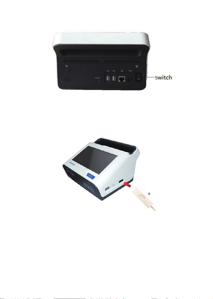
Power Switch Position
When installing the power cord the unit should be turned o. Look at the rear panel of
the instrument to check that the power switch is in the OFF position. A diagram of the rear
panel can be found in the Section Parts and Controls.
Safety Grounding
Do not alter or defeat the safety grounding methods provided. To avoid the risk of elec-
tric shock, the third prong of the AC power plug must be connected to conductive parts
internal to the equipment.
Assure Power Availability
The circuit used should be substantially free of large voltage transients (Kilovolt amp
loads) such as large pumps, large centrifuges, refrigerators and freezers, air condition-
ers, large autoclaves, ovens, and dryers. The instrument may fail to operate normally if the
power supply is interrupted. If this occurs, turn the instrument o for a moment. When the
instrument is turned back on, it will resume normal operation.

5
3.2 Parts and Controls
3.2.1 Parts of the Instrument
1. Touch screen; 2. Cassette transmit channel; 3. TEST button; 4. QR code scanning
window;
5. IC CARD reading area; 6. Thermal printing paper bin; 7. Sliding window; 8. Cassette; 9.
Thermal printing paper
10. Switch; 11. Power cord connection; 12. Internet access; 13. USB interface; 14. RE-
SET button; 15. Heat radiation window; 16. Speaker hole
Part 4: Operating Procedures
4.1 Power on/o
4.1.1 Power On
Press the switch upwards to turn on the instrument.
4.1.2 Power O
Press the switch downwards to shut down the instrument.
6
4.2 Strip Reading Operation
Put the test strip into the cassette and insert the cassette into the hole of the reader
(gure “a” bellow) and keep the lines (control and test lines) on the strip upwards. And fol-
low the test procedure to start testing.
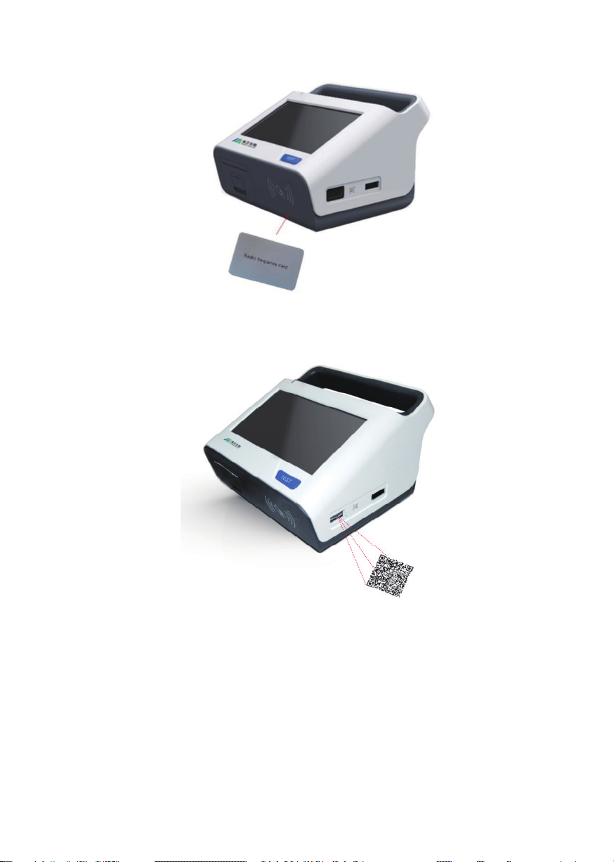
4.3 Standard Curve Input
4.3.1 Input standard curve by using IC card
Put the IC card containing standard curve information in front of the reading area (3-
5cm), the instrument will read the information in the card and the standard curve can be
input into the instrument.
7
4.3.2 Input standard curve by using QR code
Put the QR code in front of the scanning window, the instrument will read the standard
curve.
4.4 Installation of the Printing Paper
Open the cover of the bin by pull the handle and put the thermal printing paper into the
bin of the instrument. Make sure to leave some length of the paper out of the bin. Push the
cover upwards slowly until the cover closed completely.

8
Part 5: Testing Operation
5.1 Home page
Switch on to access to the home page of the instrument. There are 6 menus on this
page: “Online test”, “Quantitative test”, “Qualitative test”, “Test record”, “Standard curve”
and “Setting”.
Note: For the rst time of use, please connect to the internet by WIFI to calibrate the
calendar and time.

9
5.2 Qualitative Test Operation
5.2.1 Access to the “qualitative test” page
Tap the “ ” menu on the main page and access to the qualitative test page.
Then tap the dierent menu to select the card type, product name and batch no, etc.
The information of sample origin and test operator can be typed in manually.
5.2.2 Standard curve management
Tap the “ ” menu on the right top of this page and access to the standard curve
management page. The standard curves for dierent test kits can be entered by scanning
the IC card or the QR code. If the standard curve already exists in the list, it is not neces-
sary to scanning the IC card or QR code.
Table of contents
Other PerkinElmer Ebook Reader manuals


