PerkinElmer PS-1120 User manual

-~
ARTISAN
®
~I
TECHNOLOGY
GROUP
Your definitive source
for
quality
pre-owned
equipment.
Artisan Technology
Group
Full-service,
independent
repair
center
with
experienced
engineers
and
technicians
on staff.
We
buy
your
excess,
underutilized,
and
idle
equipment
along
with
credit
for
buybacks
and
trade-ins
.
Custom
engineering
so
your
equipment
works
exactly as
you
specify.
•
Critical
and
expedited
services
•
Leasing
/
Rentals/
Demos
• In
stock/
Ready-to-ship
•
!TAR-certified
secure
asset
solutions
Expert
team
ITrust
guarantee
I
100%
satisfaction
All
tr
ademarks,
br
a
nd
names, a
nd
br
a
nd
s a
pp
earing here
in
are
th
e property of
th
e
ir
r
es
pecti
ve
ow
ner
s.
Find the Perkin Elmer PS-1120-1 at our website: Click HERE

FF0091 UM0024 Rev L
ABCRD
PS-1120 POWER SUPPLY
OPERATION MANUAL
PerkinElmer Optoelectronics
35 Congress St., Salem, MA 01970 USA
Phone: (978)745-3200 FAX: (978)745-0894
Toll Free: (800)950-3441 in USA only
Website http://www.perkinelmer.com/opto
E-mail [email protected]
Artisan Technology Group - Quality Instrumentation ... Guaranteed | (888) 88-SOURCE | www.artisantg.com

ABCRD
FF0091 UM0024 Rev L
PS-1120 POWER SUPPLY OPERATION MANUAL
WARNUNG!
Das Netzteil PS-1120 erzeugt lebensgefährliche Spannungen. Es muss deshalb darauf geachtet
werden, dass der ankommende Strom ausgeschaltet ist und die Ladekondensatoren entladen sind,
bevor Kontrollen oder Regelungen am Gerät unternommen werden!
ATTENTION!
L'alimentation PS-1120 fournit des tensions dangereuses. Veuillez vérifier que la prise de courant es
t
déconnectée et les condensateurs d'accumulation sont déchargés avant d'entreprendre des
inspections ou des réglages sur l'appareil.
WARNING!
The PS-1120 Power Supply produces lethal voltages. Ensure that input power is
disconnected and storage capacitors have been discharged before beginning an
y
inspection or internal adjustment.
WARNING!
The output voltage of the PS-1120 MUST be limited to match the
specifications of those components to which it is connected. Exposing any
system component to voltage (or any other operating condition) that
exceeds its rating can result in damage to the unit and personal injury.
WARNUNG!
Die Ausgangsspannung des Netzteils PS-1120 muss der Leistung aller damit verbundenen
Komponenten angepasst werden. Systemelemente Spannungen (oder anderen
Betriebsbedingungen) auszusetzen, die die Leistungswerte jener Komponenten übertreffen, ist
gefährlich und kann zu Schäden und Verletzungen führen.
ATTENTION!
Il faut que la tension fournie par l'alimentation PS-1120 soit limitée aux caractéristiques des composants
auxquels il sera mis en contact. En exposant un composant quelconque à une tension (ou à d'autres
conditions de fonctionnement), qui en dépasse la limite on pourrait endommager l'appareil ou provoquer
des blessures.
WARNING!
The PS-1120 Power Supply is capable of producing 20 watts of output power.
Heatsinking of metal-can flashlamps and Lite-Pacs is required when these devices are
operated above 25 watts.
WARNUNG!
Das Netzteil PS-1120 erzeugt bis zu 20 Watt Ausgang. Bei Leistungen höher als 25 Watt müssen
Dosenlampe sowie Triggermodul, mittels eines Kühlblechs, abgekühlt werden.
ATTENTION!
L'alimentation PS-1120 fournit jusqu' à 20 watt de puissance débitée. Quand une lampe à boite en
métal et un déclenchement fonctionnent au dessus de 25 watt, il faut les refroidir au moyen d'une
source froide.
Artisan Technology Group - Quality Instrumentation ... Guaranteed | (888) 88-SOURCE | www.artisantg.com

ABCRD
FF0091 UM0024 Rev L
1
PS-1120 POWER SUPPLY OPERATION MANUAL
TABLE OF CONTENTS
PAGE
1.0 INTRODUCTION .................................................................................................................................. 2
1.1 DESCRIPTION................................................................................................................... 2
1.2 UNPACKING ..................................................................................................................... 2
2.0 SPECIFICATIONS ............................................................................................................................... 3
3.0 INSTALLATION ................................................................................................................................... 4
3.1 MOUNTING....................................................................................................................... 4
4.0 OPERATING CONDITIONS ................................................................................................................ 5
4.1 ENERGY RELATIONSHIPS............................................................................................. 5
5.0 OPERATION ........................................................................................................................................ 6
5.1 TRIGGER REQUIREMENTS ........................................................................................... 6
5.2 INTERNAL ADJUSTMENT OF HV OUTPUT REFERENCE VOLTAGE ..................... 6
5.3 EXTERNAL ADJUSTMENT OF HV OUTPUT REFERENCE VOLTAGE .................... 6
5.4 INTERCONNECTIONS..................................................................................................... 7
6.0 MAINTENANCE ................................................................................................................................... 8
6.1 REPAIRS ............................................................................................................................ 8
6.2 REPACKING AND STORAGE ......................................................................................... 8
FIGURES
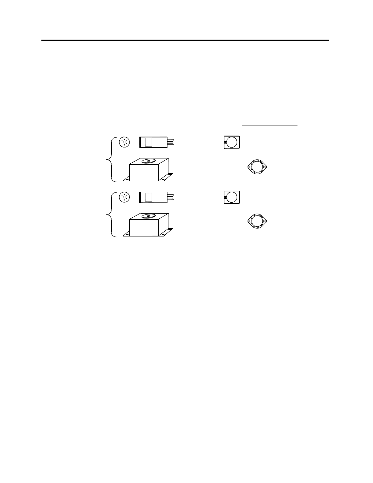
FIGURE 1. OPTIONAL PERKINELMER LITE-PACS AND ACCESSORIES ............................................ 2
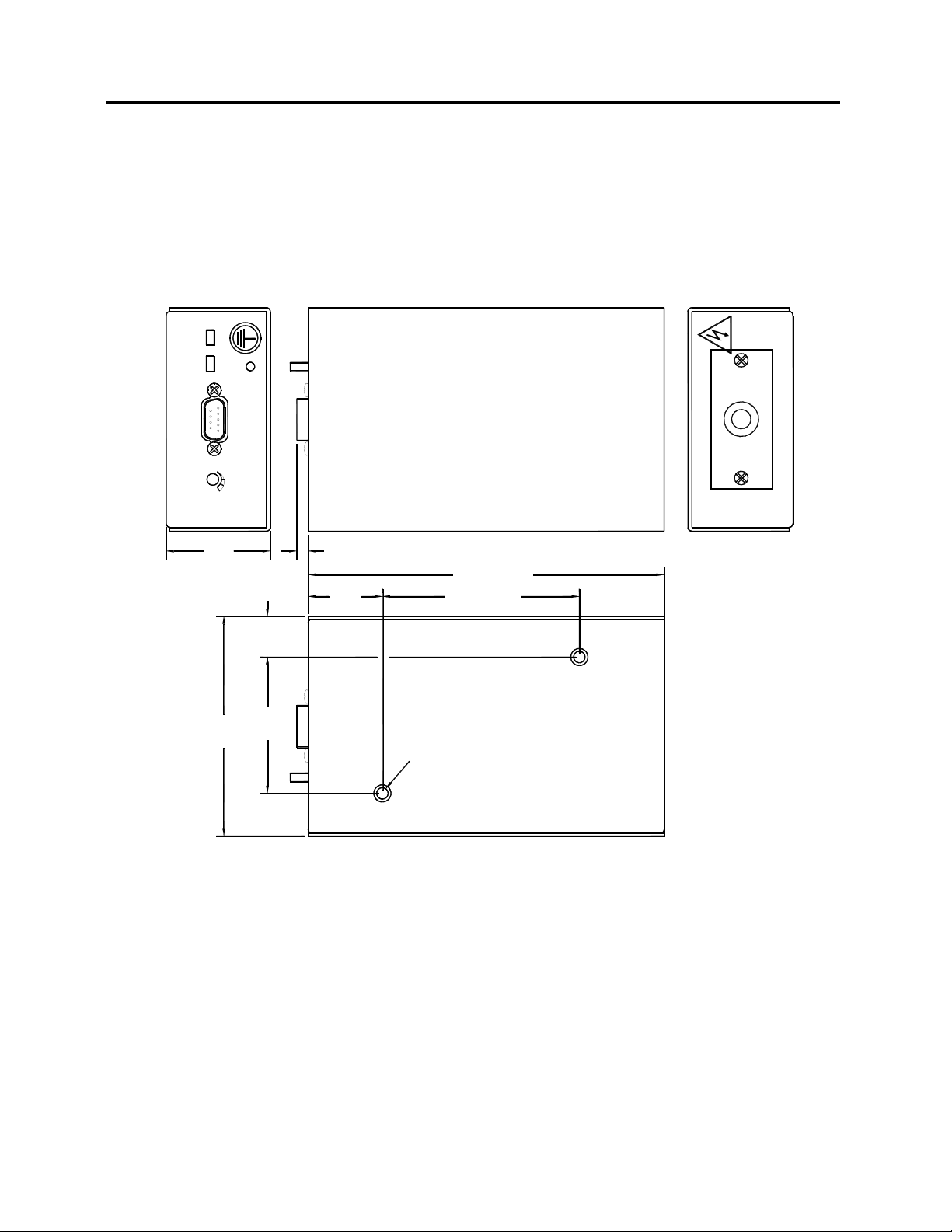
FIGURE 2. OUTLINE AND MOUNTING DIMENSIONS ............................................................................. 4
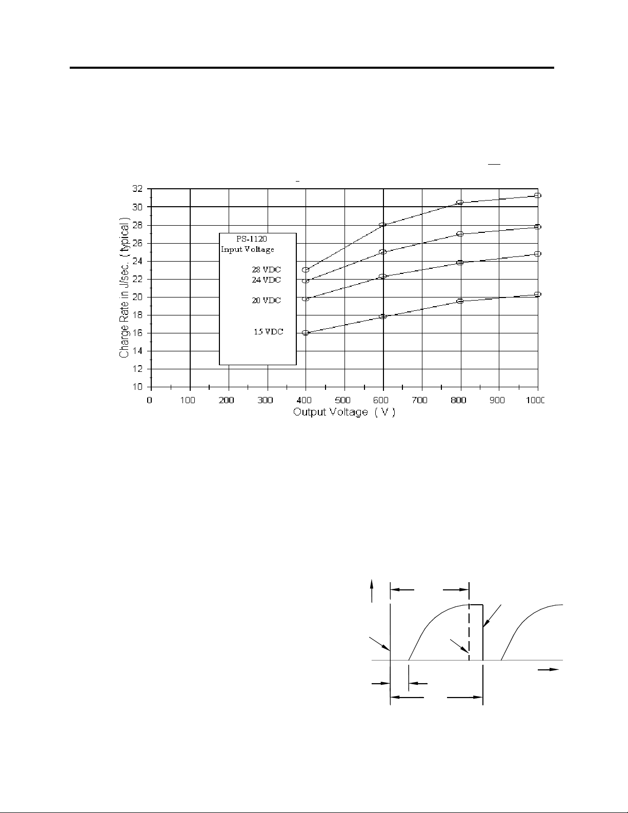
FIGURE 3. PS-1120 TYPICAL CHARGE RATE CURVES. ....................................................................... 5
FIGURE 4. OUTPUT VOLTAGE VS. TIME................................................................................................. 5
FIGURE 5. INPUT TRIGGER CIRCUIT....................................................................................................... 6
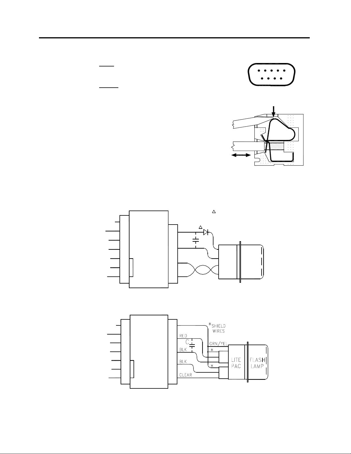
FIGURE 7. J1 INPUT CONNECTOR .......................................................................................................... 7
FIGURE 8. J2 OUTPUT CONNECTOR CROSS SECTION ....................................................................... 7
FIGURE 9. TYPICAL CONNECTIONS (STANDARD LITE-PAC WIRING) ............................................... 7
FIGURE 10. TYPICAL CONNECTIONS (SHIELDED LITE-PAC WIRING) ...............................................7
TABLES
TABLE 1. ELECTRICAL INPUT ................................................................................................................. 3
TABLE 2. ELECTRICAL OUTPUT (DISCHARGE) .................................................................................... 3
TABLE 3. ELECTRICAL OUTPUT (TRIGGER)..........................................................................................3
TABLE 4. MECHANICAL PROPERTIES.................................................................................................... 3
TABLE 5. ENVIRONMENTAL SPECIFICATIONS ..................................................................................... 3
Artisan Technology Group - Quality Instrumentation ... Guaranteed | (888) 88-SOURCE | www.artisantg.com

ABCRD
FF0091 UM0024 Rev L
2
PS-1120 POWER SUPPLY OPERATION MANUAL
1.0 INTRODUCTION
1.1 DESCRIPTION
The PS-1120 POWER SUPPLY is one of a series of Power Supplies designed
for high energy capacitor discharge service with any guided arc bulb-type
flashlamp and Lite-Pac® including those shown below.
Figure 1. Optional PerkinElmer Lite-Pacs and Accessories
The PS-1120 Power Supply performs two functions: (1) charges the flashlamp
discharge capacitor to a specific voltage at a specified rate, and (2) provides
trigger capacitor charging and switching functions at the required flash rate. Its
well regulated, low ripple characteristics ensure excellent discharge repeatability.
1.2 UNPACKING
If the condition of the outer packaging suggests mishandling has occurred,
examine the unit for any signs of breakage during shipment. If there are any
obvious signs of damage, contact the carrier immediately and do not proceed
with the installation. It is recommended that the packaging material be retained
and stored in the event that the unit has to be reshipped.
FYD-1150
FYD-1151
FYD-1150B
FYD-1151B
FLASHLAMP
METAL CAN
FOR 3.0mm
FOR 1.5mm
FLASHLAMP
METAL CAN
XP-0775
CLAMP/SHIELD
FLASHLAMP
LITE PAC MOUNTING CLAMP
XP-0777
XP-0775
LITE PAC MOUNTING CLAMP
CLAMP/SHIELD
FLASHLAMP
XP-0777
LITE-PACS ACCESSORIES
Artisan Technology Group - Quality Instrumentation ... Guaranteed | (888) 88-SOURCE | www.artisantg.com

ABCRD
FF0091 UM0024 Rev L
3
PS-1120 POWER SUPPLY OPERATION MANUAL
2.0 SPECIFICATIONS
Table 1. Electrical Input
Voltage 15-28V DC
Current Less than 1.2A DC @ 24V DC, 20W output
Trigger Optically isolated; 20-50mA peak input; 10-20µs pulse
width; leading edge trigger. Int. series resistor = 150Ω.
Vref (V0/Vref=100) 4-10V DC
Table 2. Electrical Output (Discharge)
Voltage (Vo) 400-1KV DC ±2%
Charge Rate, min. 15 J/sec (15V input, 600V output)
20 J/sec (24V input, 600V output)
Power Output 20 watts max.
Line Regulation ±1%
Ripple 0.5%, with 0.1µF, 600V charge (P-Pmax)
Internal Discharge Cap PS-1120-1
0.1µF ±10%
PS-1120-2
0.25µF ±10%
PS-1120-3
0.5µF ±10%
Table 3. Electrical Output (Trigger)
Trigger Voltage 175±15V
Trigger Capacitor 0.1µF
Max. Pulse Rate 60/J where energy per flash, J = ½ capacitance x voltage2
(J = ½ CV2). Do not exceed 1KHz
Recharge Delay 200µsec (typical)
Table 4. Mechanical Properties
9 pin "D" subminiature; mating connector supplied
Output Connector Wago Terminal Strip
Enclosure Metal Case
Dimensions 5.85"L x 3.63"W x 1.70"H
Weight 22.5 oz. (635g)
Table 5. Environmental Specifications
Operating Temperature +32°F to +104°F (0°C to +40°C)
Storage Temperature -40°F to +194°F (-40°C to +90°C)
Artisan Technology Group - Quality Instrumentation ... Guaranteed | (888) 88-SOURCE | www.artisantg.com

ABCRD
FF0091 UM0024 Rev L
4
PS-1120 POWER SUPPLY OPERATION MANUAL
3.0 INSTALLATION
3.1 MOUNTING
Two 6-32 UNC threaded holes in the base of the enclosure are provided for
mounting the unit (see Figure 2). Mounting hardware is user-supplied.
Figure 2. Outline and Mounting Dimensions
PS-1120 POWER SUPPLY
3.25 (82.6)
6-32 UNC THREADED MOUNTING HOLE
0.23 (5.8) MAXIMUM PENETRATION
5.85
(43.4)
(57.2)
2.25
(17.5)
0.69
(92.2)
3.63
BOTTOM VIEW
(30.5)
1.20
V OUT
1.71
J1
EXT INT
EXT
INT
TRIGGER V REF
(4.8)0.19
(2 PLACES)
(148.6)
(MILLIMETERS)
DIMENSIONS
ARE IN INCHES
A SHIELDING ENTRANCE PLATE FOR J2 IS PROVIDED.
7
J2
123456 8
Artisan Technology Group - Quality Instrumentation ... Guaranteed | (888) 88-SOURCE | www.artisantg.com

ABCRD
FF0091 UM0024 Rev L
5
PS-1120 POWER SUPPLY OPERATION MANUAL
t=8.0ms
FIRES
±30us
HOLD-OFF
200us
0
0
OUTPUT
VOLTAGE (V)
t=0
TUBE
TIME
CHARGE
TIME(t)
FIRES
TUBE
1/f
4.0 OPERATING CONDITIONS
4.1 ENERGY RELATIONSHIPS
At 24V input, 600V output, the unit delivers a minimum of 20 joules per second to
the discharge capacitor. Figure 3.1 shows typical charge rate values vs output
voltage for four different DC inputs.
Figure 3. PS-1120 Typical Charge Rate Curves.
The energy per discharge is given by the expression:
J = Discharge energy
C = Discharge capacitance
V = Output voltage
Power is determined by P= J x Flashrate
Long-term (1 minute or more) average
power must be limited to 20 watts.
Therefore, the sum total of the
accumulated energy discharges
(Joules) divided by the operating
period (seconds) must be ≤20 watts.
The flashtube may be fired any time
after the charge time (see Fig. 4).
Figure 4. Output Voltage vs. Time
Artisan Technology Group - Quality Instrumentation ... Guaranteed | (888) 88-SOURCE | www.artisantg.com

ABCRD
FF0091 UM0024 Rev L
6
PS-1120 POWER SUPPLY OPERATION MANUAL
J1
4-
+
5
150
ISOLATOR
OPTICAL
5.0 OPERATION
Once operating conditions have been determined, proceed as follows:
5.1 TRIGGER REQUIREMENTS
Move the trigger switch to the EXT position
(See Figure 2). Triggering is accomplished
by connecting J1-5 to +5V and J1-4 to
ground. Other logic voltages may be
accommodated by including a series
resistor. See specifications (Section 2)
for additional information.
Figure 5. Input Trigger Circuit
The PS-1120 can be tested for proper Operation by moving the TRIGGER switch
to the INT position. The unit should now flash at a low rate.
5.2 INTERNAL ADJUSTMENT OF HV OUTPUT REFERENCE VOLTAGE
The output voltage is programmed from 400V to 1KV by varying the VREF input
from 4.0 to 10.0 volts. The adjustment pot, VOUT, is available through a hole in
the J1 input panel (see Figure 2). The VREF switch must be in the INT position,
as shipped from the factory.
5.3 EXTERNAL ADJUSTMENT OF HV OUTPUT REFERENCE VOLTAGE
Move the VREF switch to the EXT position (See Figure 2). Program the output
voltage from 400V to 1KV by varying the VREF from 4.0 to 10.0 volts.
The Vref Power Supply may be programmed to zero, with the HV output (V)
dropping to less than 60V. Note that the power and Vref returns are connected
internally.
Artisan Technology Group - Quality Instrumentation ... Guaranteed | (888) 88-SOURCE | www.artisantg.com

ABCRD
FF0091 UM0024 Rev L
7
PS-1120 POWER SUPPLY OPERATION MANUAL
15
96
TERMINAL STRIP
WIRE
SCREWDRIVER
5.4 INTERCONNECTIONS
1. Make input connections according to Figure 7
and 9 or 10 (whichever is appropriate).
2. Make output connections according to Figure 8
and 9 or 10. When using a standard wiring
Lite-Pac, twist together the brown and white
Lite-Pac trigger leads and connect them to the
appropriate terminals on the output panel.
3. Add external capacitor(s) and trigger diode, if
required, to the Lite-Pac discharge circuit.
4. Turn on the power supply.
5. Set the high voltage by adjusting the reference
voltage.
6. Trigger as Required
Figure 7. J1 Input
Connector
Figure 8. J2 Output
Connector Cross Section
Figure 9. Typical Connections (Standard Lite-Pac Wiring)
Figure 10. Typical Connections (Shielded Lite-Pac Wiring)
8
J2
5
2
1
TRIG IN 5
Vref RTN
CASE GND
DC RTN
9
8
6,7
DC IN
Vref IN
1,2
4
3
PS-1120
J1
WHT
BRN
PAC
LITE
LAMP
FLASH
INTERNAL DIODE.
FYD LITE-PACS HAVE
FY SERIES LITE-PACS.
DIODE USED ONLY ON
C
BLK
RED
TRIG RTN
55
CASE GND
19
8
6,7 2
3,41,2
4
38
PS-1120
J1 J2
DC IN
Vref IN
TRIG RTN
TRIG IN
DC RTN
Vref RTN
Artisan Technology Group - Quality Instrumentation ... Guaranteed | (888) 88-SOURCE | www.artisantg.com

ABCRD
FF0091 UM0024 Rev L
8
PS-1120 POWER SUPPLY OPERATION MANUAL
6.0 MAINTENANCE
6.1 REPAIRS
The PS-1120 Power Supply is, generally speaking, a trouble-free unit. No
routine maintenance or repair is required.
The power supply is protected by a 7A slo-blow fuse in one leg of the DC input.
If this fuse opens, do not replace it. Return the unit to the factory for repair.
In the event that the unit fails or does not function properly, it is strongly
suggested that no attempt be made to troubleshoot. Field repairs or customer
modifications are not authorized, and, if attempted, will void the warranty.
Repairs must be made only by factory-trained personnel.
6.2 REPACKING AND STORAGE
If the PS-1120 is to be stored for a prolonged period, shipped to another location,
or returned to the factory for repair, it should be repacked in the original
packaging material. If the packaging material has been discarded, the unit
should be packaged in a suitable container with sufficient protective material to
ensure that the unit cannot move within the package and is protected from
damage that could occur from improper handling.
Any storage area used for the unit should be dry, at a temperature of -40°F to
+194°F (-40°C to +90°C).
WARNING!
The PS-1120 output voltage MUST be limited to match the
specifications of those components to which it is
connected. Exposing any system component to voltage (or
any other operating condition) that exceeds its rating can
result in damage to the unit and personal injury.
Artisan Technology Group - Quality Instrumentation ... Guaranteed | (888) 88-SOURCE | www.artisantg.com

Artisan
Technology
Group
is
an independent supplier
of
quality pre-owned equipment
Gold-standard
solutions
Extend the life
of
your
critical industrial,
commercial, and military systems
with
our
superior service and support.
We
buy
equipment
Planning to
upgrade
your current
equipment? Have surplus equipment taking
up shelf space? We'll give it a
new
home.
Learn
more!
Visit us at artisantg.com for more info
on price quotes, drivers, technical
specifications, manuals, and documentation.
Artisan Scientific
Corporation
dba
Artisan
Technology
Group
is
not
an affiliate,
representative,
or
authorized
distributor
for
any
manufacturer
listed herein.
We're here to make your life easier.
How
can
we
help you today?
(217)
352-9330
Isales@artisantg.com Iartisantg.com
Table of contents
Other PerkinElmer Power Supply manuals