Page4
~
Safety precautions
THESE SAFETY PRECAUTIONS ARE IMPORTANT. Reference must also be made to the local
regulations in the country of operation.
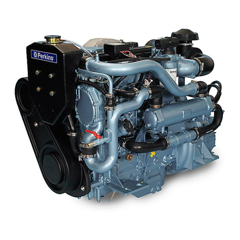
Do not use these engines in marine applications.
Do
not
change the specification
of
the engine.
Do
not
smoke when you
put
fuel in the tank.
Clean away any fuel which has fallen and move material which has fuel contamination to a safe
place.
Do
not
put
fuel in the tank during engine
operation
(unless really necessary).
Never clean, lubricate
or
adjust the engine
during
operation (unless you have had the
correct
training when extreme caution must be used to prevent
injury).
Do not make any adjustments you do not understand.
Ensure the engine is not in a position to cause a concentration of toxic emissions.
Persons in the area must be kept clear during
engine
and equipment
or
vehicle operation.
Do not permit loose clothing
or
long
hair
near parts which move.
Keep away from parts which turn during operation. Note that fans can
not
be seen clearly while
the engine is run.
Do not run the engine with any safety guards removed.
Do not remove the radiator cap while the
engine
is hot and the
coolant
is
under
pressure as
dangerous
hot
coolant
can be discharged.
Do
not
use salt water in the cooling system
or
any
other
coolant which can cause corrosion.
Keep sparks
or
fire away from batteries (especially during charge)
or
combustion can occur.
The battery fluid can burn and is also dangerous to the skin and especially the eyes.
Disconnect the battery terminals before you make a repair to the electrical system.
Only one person must be in control of the engine.
Ensure the engine is only operated from the
control
panel
or
operators position.
If your skin comes into
contact
with high pressure fuel,
get
medical assistance immediately.
Diesel fuel can cause skin damage to some persons. Use protection on the hands (gloves
or
special skin protection
solutions).
Do
not
move equipment unless the brakes are in
good
condition.
Ensure that the transmission drive control is in
"Out
of
Drive"
position
before the engine is
started.
Fit only
correct
Perkins Parts.

