10
Connection using the internet is indicated by the
‘IP’ LED = [Green –Steady On]
Using the Alarm Panels dialler
The alarm panel must be programmed with:
Contact ID (format)
Tone / DTMF dialling
Four digit Panel ID number
8 digit telephone number (e.g. 12345678)
Arm & Disarm reporting must be enabled. (This is required for the Pocket Secure App)
Force the alarm panel to send a Contact ID event to the monitoring station
The PM45-3G v1 obtains the Panel ID directly from the Alarm Panel after the first valid
contact ID event is sent.
If a fixed Account ID is required - Contact the Monitoring Centre before and have them fix it
in the PM45-3G v1.
Testing
Ping the PM45-3G v1 using Atlas
Initially the CID Led will be off
Force the alarm panel to send a Contact ID event to the monitoring station
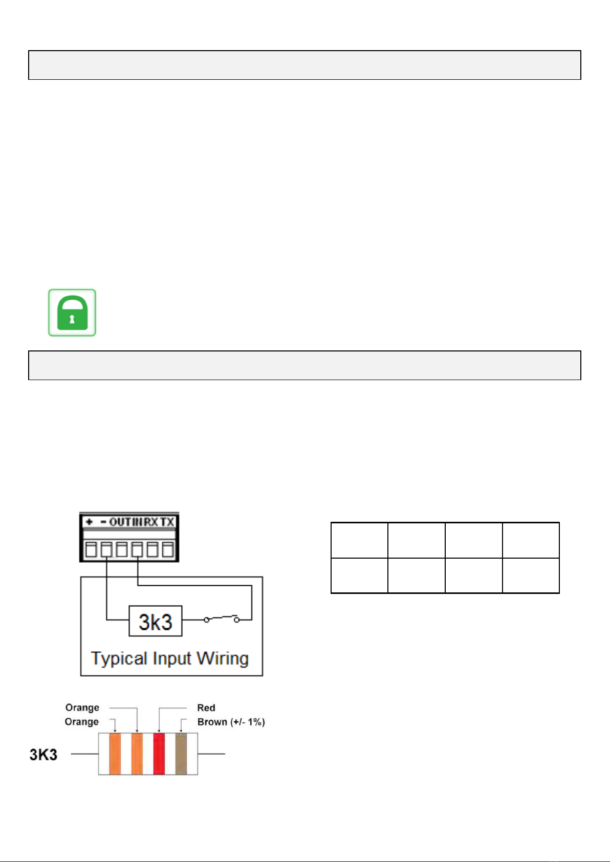
The panel dialler will seize the dialler line and send data on pins 2 & 3.
The ‘CID’ LED = [Green - Blinking].
NB: When the panel seizes the dialler line the voltage between on pins 1 & 4
The voltage on pins 2 & 3 should drops from 48vDC to 6-12vDC
Atlas will display Dialler Interface FAIL (normal)
When a valid Contact ID event is sent from the alarm panel and the panel releases the line.
The ‘CID’ LED = [Green - Steady On].
NB: When the panel releases the dialler line it restores the 48vDC on pins 1 & 4 Atlas
will display Dialler Interface OK (normal)
Installation Procedure continued.....
RDCCO_2149_E_INPM45-3G v1 March 2019 v1.4