9
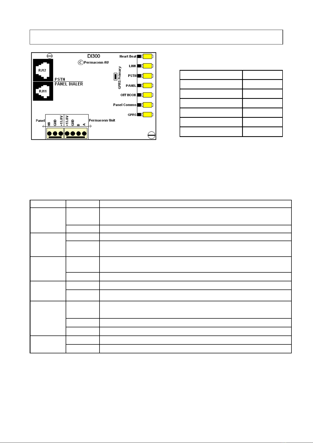
LED Status Indicators PM1030
LED Activity Indication
POWER On * Indicates battery or 14.5 Volt Power
Off Indicates unit is off
GSM
On * Unit not activated or network is not avail-
able
Blinking (1 sec On -1
sec Off) Searching for 3G network
Flashing once Connected to GSM Network
Flashing twice * Indicates connectivity with Permaconn net-
work
SIM On Indicates unit is connected on 'B' sim
Off Indicates unit is connected on 'A' Sim
BATTERY On Indicates low battery voltage or no battery
connected
Off * Battery voltage correct
SIGNAL
STRENGTH
LIndicates Low signal strength
M * Indicates Medium signal strength
H * Indicates High signal strength
COMMS
Blinking * Indicates serial /RS485/RS232 connec-
tivity with alarm panel or DI300
Off No serial connection between DI300 and
Permaconn
ONLINE/
GPOL
On * Normal operation Unit is connected to Per-
maconn network.
Off No connection to network
Blinking
Unit is registered on Permaconn Network
but has not received message with ac-
count details from the alarm panel.
On for 2 seconds 1
flash Only SIM A is active
On for 2 seconds 2
Flash Only SIM B is active
HEART BEAT Blinking * Indicates the unit has completed a power
up test and is working properly
Off No Power or unit is faulty
Normal Opera-
tion
LED Activity Indication
POWER On * Indicates battery or 14.5 Volt Power
Off Indicates unit is off
GSM
On * Unit not activated or network is not available
Blinking (1 sec On -1 sec Off)
Searching for 3G network
Flashing once Connected to GSM Network
Flashing twice * Indicates connectivity with Permaconn network
SIM On Indicates unit is connected on 'B' sim
Off Indicates unit is connected on 'A' Sim
BATTERY
On Indicates low battery voltage or no battery con-
nected
Off * Battery votage correct
SIGNAL
STRENGTH
LIndicates Low signal strength
M * Indicates Medium signal strength
H * Indicates High signal strength
COMMS
Blinking * Indicates serial /RS485/RS232 connectivity with
alarm panel or DI300
Off No serial connection between DI300 and Per-
maconn
ONLINE/GPOL
On * Normal operation Unit is connected to Permaconn
network.
Off No connection to network
Blinking Unit is registered on Permaconn Network but has
not received message with account details from the
alarm panel.
On for 2 seconds 1 flash
Only SIM A is active
On for 2 seconds 2 Flash
Only SIM B is active
HEART BEAT
Blinking * Indicates the unit has completed a power up test
and is working properly
Off No Power or unit is faulty
* Normal Operation
RDCCO_2143_E_IN
PM1030 Manual March 2019 v2.2