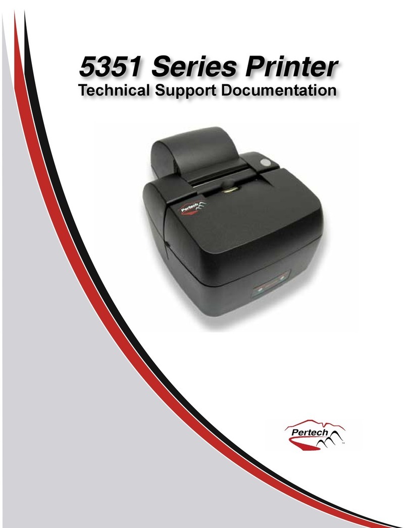
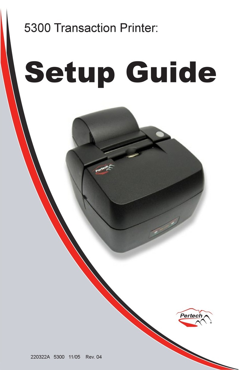
Pertech 5300 Series User manual

Users Guide
Pertech Resources Inc. November 2005 220321A-01
5300 Series Printer

Pertech Resources Inc. November 2005 220321A II
Disclaimer
Information in this document is subject to change without notice. Consult your Pertech® sales representative for information
that is applicable and current. Pertech reserves the right to improve products as new technology, components, software and
rmware become available.
No part of this document may be reproduced or transmitted in any form or by any means, electronic or mechanical, for any
purpose with out the express written permission of Pertech.
Copyright
Copyright © 2005 by Pertech Resources, Inc.
Riverton, Wyoming USA
All rights reserved
Printed in USA
Condential, Unpublished
Property of Pertech Resources, Inc.
Trademarks
PERTECH® is a registered trademark of PERTECH RESOURCES, INC.
Other trademarks and registered trademarks are the property of their respective holders
Web site
http://www.pertechresources.com/
Federal Communications Commission (FCC) Radio
Frequency Interference Statement
Warning
Changes or modications to this unit not expressly approved by the party responsible for compliance could void the user’s
authority to operate the equipment.
Note
This equipment has been tested and found to comply with the limits for a Class B digital device, pursuant to Part 15 of the
FCC rules. These limits are designed to provide reasonable protection against harmful interference when the equipment is
operated in a commercial environment. This equipment generates, uses, and can radiate radio frequency energy and , if
not installed and used in accordance with the instruction manual, may cause harmful interference to radio communications.
Operation of this equipment in a residential area is likely to cause harmful interference in which case the user will be
required to correct the interference at his own expense.
Information to the User
This equipment must be installed and used in strict accordance with the manufacturer’s instructions. However, there is no
guarantee that interference of radio communications will not occur in a particular commercial installation. If this equipment
does cause interference, which can be determined by turning the equipment off and on , the user is encouraged to contact
Pertech immediately.
Pertech is not responsible for any radio of television interference caused by unauthorized modication of this equipment, or
the substitution of attachment or connection cables and equipment other than those specied by Pertech. The correction of
interferences caused by such unauthorized modication, substitution or attachment will be the responsibility of the user.
Industry Canada
This Class B digital apparatus complies with Industry Canada Standard ICES-003.
Cet appareil numérique de la classe A est conforme à la norme NMB-003 d’Industrie Canada.

Pertech Resources Inc. November 2005 220321A III
Important Information to the User
In order to ensure compliance with the Product Safety, FCC and CE marking requirements. you must use the power supply,
power cord, and interface cable which were shipped with this product or which meet the following parameters:
Power Supply
Input power to this product must be provided by one of the following:
(1) A NRTL Certied power source with a Limited Power Source
(LPS) output for use in North America, input rated 100 - 240 Vac, 1.5 A, 50/60 Hz, Output rated 24Vdc, 2.5 A Maximum and
60W Maximum. or
(2) A power source with a Limited Power Source (LPS) output Certied by an agency recognized in the country of
installation, input rated 100 - 240 Vac, 1.5 A, 50/60 Hz, Output rated 24Vdc, 2.5 A Maximum and 60W Maximum. Use of this
product with a power supply other than the Pertech power supply will require you to test this power supply and the Pertech
printer for FCC and CE mark certication.
Interface Cable
A shielded (360 degree) interface cable must be used with this product. The shield must be connected to the frame or earth
ground reference at each end of the cable.
Use of a cable other than the described here will require that you test this cable with the Pertech printer and your system
for FCC and CE mark certication.
Power cord
For North America a NRTL Recognized detachable power cord must be used. For applications where the power supply
module may be located on the oor, a power cord with Type SJT marking must be used.
For applications outside of North America, Power cords which meet the country of installation’s certication and application
requirements must be used.
Use of a power cord other than described here may result in a violation of safety certications which are in force in the
country of use.

Pertech Resources Inc. November 2005 220321A IV
Contents
Preface ............................................................................................................... VI
About The Printer ................................................................................................1
Features and Options .................................................................................1
Choosing a Location...................................................................................1
Unpacking the Printer .................................................................................1
Ordering Paper and Supplies .....................................................................2
Operating the Printer...........................................................................................3
Using the Controls ......................................................................................3
Paper Loading ............................................................................................3
Cartridge Installation & Replacement .........................................................4
Validation and Document Guides ......................................................................5
Validation Print Fields .................................................................................5
Document Guide Installation ......................................................................6
Cables and Connections.....................................................................................7
Comunications............................................................................................7
RS232 Serial Interface ...............................................................................7
RS-232 Interface Connection ..........................................................7
USB 2.0 Interface .......................................................................................8
Cash Drawer...............................................................................................8
Power Supply .............................................................................................9
Drivers & Utilities ..............................................................................................10
XP/2000 Windows Driver..........................................................................10
Driver Installation ...........................................................................10
Print Driver Setup..........................................................................12
Printer Conguration ...........................................................13
Printing Preferences ...........................................................14
Printer Commands .............................................................14
Logo Download Utility..............................................................................16

Pertech Resources Inc. November 2005 220321A V
Conguration & Diagnostic Print Tests ..........................................................17
Conguration Utility Program....................................................................17
Printer Control Language...............................................................18
Font ...............................................................................................19
RS232 Interface ............................................................................19
USB Interface ...............................................................................19
Hardware .......................................................................................19
Memory..........................................................................................20
Tallies.............................................................................................20
Conguration Report & Setup Mode.........................................................21
Printer Conguration Options ...................................................................23
Options for ACL Compatibility Mode .............................................23
Options for A470 Compatibility Mode ...........................................24
Options for Mode 1, 2, 3, 4 & 5 (DO214, ZC2979, ZC5979 ZC1939 &
ZC2059) ........................................................................................25
Compatibility Modes .....................................................................25
LED Mode Indicators ...............................................................................26
Trouble Shooting Printer Problems .................................................................27
LED Error Fault Mode Diagnostics ...........................................................27
Trouble Shooting General Issues .............................................................28
Service & Support.....................................................................................29
Maintaining The Printer.............................................................................29
Specications ....................................................................................................30
Index ...................................................................................................................32
Warranty .............................................................................................................33

Pertech Resources Inc. November 2005 220321A VI
Preface
This manual has been written to help you Install and Operate your Pertech® 5300 Series Printer. Feel free to contact
us if you need further assistance after reading this manual. Please see the Troubleshooting Printer Problems section of
this manual and determine the complete part number of your printer prior to calling. Pertech provides technical support
Monday through Friday from 8:00 AM to 5:00 PM MST at 307-856-4821.
Every effort has been made to insure the information in this manual is complete and accurate. Feel free to contact us
with any comments concerning this manual. Pertech assumes no responsibility for errors.
Where to Get Additional information
The following publications contain more information about the 5300 series printer. Contact your Pertech sales repre-
sentative to obtain additional copies of this Manual or any of the publications listed below.
Title Part Number
5300 Printer: Setup Guide 220322
5300 Printer: Users Guide 220321
5300 Printer: Service Guide 220323
5300 Printer: Programming Manual A470 220282
5300 Printer: Programming Manual ACL 220320
5300 Printer: Programming Manual D0214 220284
5300 Printer: Programming Manual ZC 5999 / 5979 220285
5300 Printer: Programming Manual ZC 2979 220286
5300 Printer: Programming Manual ZC 1939 / 2059 220325
Available Models:
5351 Ink Jet Receipt / Independent Validation
5354 Ink Jet Validation Only
5371 Impact Receipt / Independent Validation
5374 Impact Validation Only

Pertech Resources Inc. November 2005 220321A 1
About The Printer
Unpacking the Printer
Save all packing materials in case you need to repack the
printer.
To report a printer that was damaged during shipping, see
“Contact Information” on the last page of this Guide.
To repack the printer, consult the illustration and use the
original packing materials.
Choosing a Location
Place the printer on a level surface on or near
the host computer. Leave space to open the
cover, change the paper, Ink or ribbon Car-
tridge, and to insert a form.
The maximum distance from the printer to the
host and the power supply is: 20 feet (RS-232
serial interface).
Features and Options
Automatic paper loading.
Serial and USB Standard interfaces
One button conguration.
Validation / Receipt and Validation Only
Models.
Impact / Ink Jet conversion capability 535X Packing Shown

Pertech Resources Inc. November 2005 220321A 2
Ordering Paper and Supplies
The following section lists the paper and supplies available for order. In addition to paper and ribbons,
parts, service and repair may be obtained by calling 1-800-800-6614.
Paper:
Call: 1-800-800-6614
Paper Part Number
Ink Jet 5351
One Ply....................................................................................................... 103292057
Impact 5371
One Ply....................................................................................................... 103292062
Two Ply....................................................................................................... 103292061
Cartridge’s:
Call: 1-800-800-6614
Description Part Number
Ink Jet 535X
Black........................................................................................................... 108541001
Impact 537X
Black........................................................................................................... 100629011
Purple ......................................................................................................... 100629012
Cables:
Call: 1-800-800-6614
Description Part Number
5300 Printer RS232 Serial Cable ................................................................. 106356010
5300 Printer Certied USB Cable ............................................................... 106356011
Documentation:
Call: 1-800-800-6614 - or downloadable at www.pertechresources.com
Title Part Number
5300 Printer: Setup Guide ............................................................................ 220322
5300 Printer: Users Guide .......................................................................... 220321
5300 Printer: : Service Manual ..................................................................... 220223
Parts Information Manual (PIM)..................................................................... 220324

Pertech Resources Inc. November 2005 220321A 3
Operating the Printer
Using the Controls
Paper Loading
Failure to load paper correctly may result in a paper jam. To remove paper that has jammed:
1. Open the Front Cover.
2. Pull the paper backwards out of the mechanism. If the paper will not remove pull the paper
forwards out of the mechanism. If needed cycle power to the printer and wait 5 seconds.
Drop roll into paper bucket so that paper comes off the bottom of the paper roll. Insert the paper end into the paper
feed actuator assembly. The paper feed actuator will automatically feed the paper through the mechanism . Close
the paper cover lid, paper loading is complete.
To load paper the power must be turned ON. Refer to the pictorial paper loading instructions in the Paper Roll
Cover. Follow the instructions on this page.
The 5300 printer includes the
following controls :
•Paper feed button used to
advance paper.
•Power switch used to turn the
printer on and off.
Paper and other printer consumables may be purchased from Pertech by calling 1-800-800-6614.
Roll paper must be 3.0 inches wide +/- .03 inches (.762mm) with a maximum diameter of 3.5 inches (88.9mm).
Ink Jet 535X receipt printers can accommodate 1 paper ply. Impact 537X receipt printers can accommodate 1 or two
paper plys. The minimum inside core diameter is 5/8 inches (15.875mm).
Inserted forms allow for one original plus 2 additional copies, this includes the receipt roll paper if used. Minimum
form size is 5.5 inches by 2.75 inches (139.7 by 69.9mm) with thickness between .0015 to .0047 inches (.0381-
.1194mm) for 2 ply s, .0026-.0047 for 1ply(.066-.1194mm) . Total media thickness allowed is no more than .012
inches (.305mm) includes the receipt.
Incorrect
Correct

Pertech Resources Inc. November 2005 220321A 4
Ribbon Advance Knob
535X Ink Jet Specic Directions
4. Remove the protective vinyl tape from replacement print cartridge.
Do not touch the Ink nozzles.
Do not touch or remove the copper contacts.
5. Push the print cartridge rmly, angled down into the print
cartridge cradle, cradle latch will latch automatically.
6. Close the front cover.
Cartridge Installation & Replacement
1. Press the Power Switch to turn on the printer.
2. Open the front cover. The printhead cradle will move to an accessible position.
3. If replacing print cartridge lift the print cartridge out and discard. Skip this step if no print cartridge is installed.
Note: Replacement ink jet print cartridge for your printer 108541001
Replacement impact print cartridge for your printer 100629011 Black
100629012 Purple.
Warning: Printer is shipped without the print cartridge
installed. When shipping or transporting printer remove the
ink cartridge to prevent damage to the printer. Ink cartridges
should be shipped in original packaging only.
To reset the Ink Status - Close and Re-Open the Cover after Step 3
(See INK STATUS RESET in Conguration section of this manual for available options.)
537X Impact Specic Directions
4. Remove the cartridge from its protective plastic bag.
5. Angle the exposed ribbon end over the print head carriage
In front of the two ribbon guides.
6. Lightly push the ribbon case down until it is engaged into
the ribbon advance gear on the right side and the ribbon
cartridge is ush in the ribbon carrier.
NOTE: It may be necessary to turn
the ribbon advance knob clock
wise during Installation to engage
the ribbon advance gear.

Pertech Resources Inc. November 2005 220321A 5
2.75 Inches
1.75 Document Stop
Right Edge of Form Aligned with Right
Edge of Receipt Retail Endorsement. To
center justify check in print zone, docu-
ment guide is 2.625” from dot column #1
1 Inch
Print eld is 2.5” Wide
Right Justify
Validation Print Fields
The 5300 series printer has 2.5 inch wide printeld.
The validation print eld height is adjustable from .17 to 1.75
inches. This can be done via the conguration utility or the
one button setup. An inserted form can be manually aligned
or a optional document guide can be attached to provide a
xed right side stop for the inserted form. The drawings be-
low indicate the typical print positions for a 2 3/4” X 6” form.
The highlighted area is the printeld width and Maximum
height.
Note: The one button set-up only has three selectable docu-
ment stop settings. Using the Conguration Utility the docu-
ment stop can be adjusted to any desired printeld height
within the parameters specied above.See Conguration and
Diagnostics section of this manual for available options.
3 Inches 1 InchPrint Zone
2 Inches for 6” Check
Print eld is 2.5” Wide
Left Justify
3 Inches
3 Inches 1 Inch
Print eld is 2.5” Wide
Right Justify
3.5 Inches
3 Inches 1 Inch
Print eld is 2.5” Wide
Center Justify
3.25 Inches
Bank of F irst Deposit (BOFD) Endorsement A470, bit [print eld is ;larger
Dot column #1 Dot Column #400
Print Zone
2 Inches for 6” Check
Print Zone
2 Inches for 6” Check
3 Inches 1 Inch
Print eld is 2.5” Wide
Right Justify
2.75 Inches
Right Edge of Form Aligned with Right
Edge of Receipt BOFD Endorsement
Effective print area in Endorsement zone
is 1.75” wide.
Print Zone
2 Inches for 6” Check
1.75 Document Stop
1.75 Document Stop
1.75 Document Stop
1.75 Document Stop
Validation and Document Guides
3 Inches1 Inch
Print Zone
2 Inches for 6” Check
Doc ument Guide
2.5” Wide Print Field
Left Justify
Right Justify
To 2” Print Zone:
Note: The Print Field is 2.5” wide. Left Justication
will overlap into the 1” right zone. Right Justica-
tion will overlap into 3” left zone.

Pertech Resources Inc. November 2005 220321A 6
Document Guide Installation
The Document Guide is a clip in durable plastic part that attaches to the printers Validation Roller to provide a
right side guide for an inserted form.
NOTE: Before installing the Document Guide make sure the area where the guide is to be installed is free of
any dust debris or contamination that could inhibit the movement of the Validation Roller.
The Document Guide is installed by
attaching it to the Validation Roller. The
guide is installed vertically with the bot-
tom of the guide clipped into the Valida-
tion Roller in the rollers notch on the
right side. The tapered tab end of the
guide needs to be toward the top of the
printer. Align the bottom two extensions
of the Document guide so that they are
left of the MLV Roller Gear. Make sure
an inserted form will not catch on the
guide.
2.75 Inches
1.75 Document Stop
1 Inch
Print eld is 2.5” Wide
3 Inches 1 Inch
Print Zone
2 Inches for 6” Check
Print eld is 2.5” Wide
3 Inches
1.75 Document Stop
When the Document Guide is attached the
Print is Left Justied to the 2” Print Zone on the
back of a 2 3/4” X 6” standard check.
Note: The Print Field is 2.5” wide. Left Justi-
cation can overlap into the 1” right zone.
Tab
MLV Gear
The print eld will be
1/4” left of a standard
2 3/4” X 6” form when
inserted vertically and
aligning with the docu-
ment guide.

Pertech Resources Inc. November 2005 220321A 7
Cables and Connections
RS232 Serial Interface
The 5300 comes with two communication interfaces, RS-232 Serial and USB. Additionally, the printer has a cash
drawer port and a three pin mini din power coupling. The RS-232 interface connector is a DB9M connector and
requires a Null Modem Serial cable for standard PC to printer connections. The USB Interface uses a standard USB
2.0 cable for standard PC to printer connections. A single tele-jack port provides a cash drawer interface capable of
running two cash drawers. An external Class 2 Power Supply provides 15 watt Min output to the printer. All connec-
tors are located on the back of the printer in the order listed below.
Power USB Serial Cash Drawer
RS-232 Interface Connection
Printer Computer
DB-9M DB-9M
Pin Pin
1 N/C 1 N/C
2.RXD ← 3
3 TXD → 2
4 DTR → 6
5 SIG. GND. ← 5
6 DSR ← 4
(TTL FORM IN) →
7 RTS → 8
8 CTS ← 7
(TTL LOW PAPER) →
9. N/C N/C
Connecting the Cables
Caution: Be sure the power switch is turned off before connecting cables. The host computer should be
turned off before connecting any cables.
1. Make sure the host computer and printer are turned off.
2. Attach the cable to the DB9 Male connector on the back of the Printer.
3 Attach the cable to the DB9 Male connector on the back of the PC.
4. Tighten the connector screws to secure the cable and ensure a solid connection.
Comunications
Serial Cable DB9F - DB9F
Part Number 106356010

Pertech Resources Inc. November 2005 220321A 8
Cash Drawer
Warning: use of incompatible cables can damage the printer and will void the warranty.
When purchasing a cash drawer for this product please make sure the vendor is aware of the product specications.
When replacing an A470 model printer, the cash drawer cable must be changed.
Pin # Signal Name Signal Source Description
1 Ground Ground
2 Cash Drawer drive #1 Printer Drive for Cash Drawer 1
3 Cash Drawer Sense Cash Drawer Cash Drawer Switch
4 Cash Drawer +24V Printer Drawer supply side.
5 Cash Drawer drive #2 Printer Drive for Cash Drawer 2
6 COM Cash Drawer Cash Sense Return (Gnd)
123456
USB 2.0 Interface
Pin 1 EOT/VCC
Pin 2 D-
Pin 3 D+
Pin 4 GND
Pin 5 GND
Pin 6 GND
The USB cable may be attached or detached when the
system is on. When Using the USB interface the Win-
dows® Operating System will automatically install the
USB port driver. Pertech has available printer drivers at
www.pertechresources.com.
Cash Drawer Y Cable
Printer
Cash Drawers
Cash Drawer Cable
Printer
Cash Drawer
Single Cash Drawer Conguration Dual Cash Drawer Conguration
(Requires Y Cash Drawer Cable Adapter, See your
cash drawer manufacture for the correct cable.)
1. Printer should be off when connecting the cash drawer.
2. Connect the cable to the cash drawer and the printer.
Warning: When Hot Swapping USB cable make
sure that cable is installed into the correct con-
nectors or damage to the printer could result.
A470 Cash Drawer Commands ASCII HEX Decimal Default 75ms Pulse
Cash Drawer “A” ESC BEL 1B 07 27 7
Cash Drawer “B” ESC BS 1B 08 27 8
ACL Cash Drawer Commands ASCII HEX Decimal
Immediate peripheral pulse DLE DC4 10 14 16 20 s m n
s: Peripheral Select
m: Peripheral On Time
n: Peripheral Off Time
Immediately generates a pulse of (m x 2 msec) followed by an off time of (n x 2 msec) on the peripheral output. If s
= 00, the rst peripheral on pin 2 is activated and if s =01, the second peripheral on pin 1 is activated.
Off Time should be set so that it is greater than or equal to On Time.
USB Cable Part
Number 106356011

Pertech Resources Inc. November 2005 220321A 9
Power Supply
To avoid damage to the printer connect the Power Supply last.
1. Make sure the printer power switch is off.
2. Plug the Power Supply Cable into the printer. The power supply cable connector has a
locking mechanism to ensure that the cable stays fastened to the printer. When removing
the cable release the locking mechanism by pulling the mechanism away from the printer.
3. Plug the Power Supply Cable into a grounded outlet.
4. Turn the power switch on. The Power LED on the front of the
Printer will illuminate to green.
INPUT
Input Voltage: 90Vac To 255Vac
Input Current: <.5Arms At 90Vac
Input Frequency 47Hz To 63Hz
OUTPUT
Output Voltage: 24VDC
Output Current: .625A Minimum, No Minimum
Load Required
Rated Output Power: 15 Watts Minimum
Load Regulation: +/- 5%
Line Regulation: +/- 1%
Ripple Voltage: 250mV Peak To Peak
Inrush Current: 30A @ 115Vac, 40A @ 230Vac
Efciency: 60% Minimum, 75% Typical
PROTECTION
Over-voltage: 25.6Vdc TO 30Vdc
Short Circuit: Auto-Recover Upon Removal
Of Short
APPROVALS
Safety Marks: UL, CSA or CUL, *CE, *TUV
EMI: FCC Part 15 Class B
(Both Radiated And Conducted)
PHYSICAL
AC Plug: On Wall Mount Adapter
DC Cord Length: 1830mm (6 FT.)
DC Plug: 3-pin Locking Mini Din
(See Pinout Above)
Connector Cable Locking
Mechanism
Ink Jet 535X Power Supply Impact 537X Power Supply
INPUT
Input Voltage: 90Vac To 255Vac
Input Current: 1.5A Max
Input Frequency 47Hz To 63Hz
OUTPUT
Output Voltage: 24VDC
Output Current: 2.5A Minimum, No Minimum
Load Required
Rated Output Power: 60 Watts Minimum
Load Regulation: +/- 5%
Line Regulation: +/- 1%
Ripple Voltage: 250mV Peak To Peak
Inrush Current: 50A @ 115Vac, 100A @ 230Vac
Efciency: 75% Minimum
PROTECTION
Over-voltage: 25.6Vdc To 30Vdc
Short Circuit: Auto-Recover Upon Removal
Of Short
APPROVALS
Safety Marks: UL, CSA OR CUL, CE, TUV
EMI: FCC Part 15 Class B
(Both Radiated And Conducted)
PHYSICAL
Ac Plug: IEC 320/C6
Dc Cord Length: 1830mm (6 FT.)
Dc Plug: 3-pin Locking Mini Din

Pertech Resources Inc. November 2005 220321A 10
Drivers & Utilities
Pertech provides drivers for various operating systems. Common drivers can be downloaded off the Pertech web
site www.pertechresources.com. For drivers not listed on the web site check with your Pertech representative for
availability.
For the 5300 to utilize the Pertech drivers or the USB communication interface a driver must be installed. When con-
necting the printer to a XP or 2000 Windows® operating system use the Pertech driver available for download off
the Pertech web site. The printer must be set into the ACL command language to function with the driver. To set the
command language see the Diagnostic & Conguration section in this manual.
Driver Installation
1. Unzip the 5300 driver package to a temporary folder.
Make a note of where this folder is located for later.
2. If using USB, connect the USB cable between the
5300 printer and computer. Then turn on the 5300. This
causes Windows to assign the 5300 to a Virtual USB
Printer Port, which will need to be selected in the “Select
Printer Port” step described below.
3. Use the “Add Printer Wizard” to install this driver on
either Windows 2000 or Windows XP. Find “Printers
And Faxes” on the “Start” menu. (Some machines may
have this section under the sub-heading “Control Pan-
el”). Click on “Add Printer” and click “Next”.
4. Select “Local Printer” and uncheck “Automatically
detect and install my Plug and Play printer”. Click “Next”.
Note that unchecking “Automatically detect...” is optional,
but speeds up the installation process.
5. To “Select a Printer Port”, pull down the drop box.
If using USB, select the virtual USB port number for
the printer. If USB001 and USB002 are shown, select
USB002. You can always change this later. If using
RS-232 serial, select the appropriate COM port that the
printer is attached and note that later you may need to
adjust RS-232 settings. Click “Next”.
XP/2000 Windows Driver

Pertech Resources Inc. November 2005 220321A 11
6. The “Install Printer Software” section will display a list
of printers that Windows currently supports and show a
button called “Have Disk”. Click “Have Disk” and browse
to the temporary folder where the driver was unzipped in
step 1. In this folder, Windows will nd “5300.INF”. Click
“Open”, then click “OK”.
Click “OK” again.
7. Four different versions of the 5300 will be listed:
5371 (impact receipt and validation)
5374 (impact validation only)
5351 (inkjet receipt and validation)
5354 (inkjet validation only).
Click on the appropriate model and click “Next”.
8. You can optionally rename your printer and assign it
as default. Click “Next”.
9. Click whether or not you want the printer to be shared
with other PC’s on a network. Click “Next”.
10. Click whether or not to print a test page and click
“Next”.

Pertech Resources Inc. November 2005 220321A 12
11. Click “Finish”. Windows will issue a warning that the
driver is not digitally signed by Microsoft®. To install the
driver, click “Continue.”
Print Driver Setup
COMx Port Set up
If using RS-232, it is likely that rst time installers will
need to adjust the RS-232 parameters to match the
attached printer. After installing the driver, go to “Print-
ers and Faxes” on the “Start” menu and right click on
the 53xx printer driver. Select “Properties”. Select the
“Ports” tab. Select “Congure Port”. Verify that the baud
rate, parity data and stop bits and ow control match.
VERY IMPORTANT: Make sure that the Windows COM
port is set for Flow Control = Hardware (or XON/XOFF if
the attached printer is congured to for XON/XOFF). If
Flow Control is set to “None”, garbage print may eventu-
ally result. To check the printers conguration settings
see the next section of this manual “ Conguration &
Diagnostic Print Tests”.

Pertech Resources Inc. November 2005 220321A 13
Bi-directional Status
The printer driver will display printer status via an icon in
the Windows System Tray, which is located on the task
bar next to the clock. There are several different icons
that could be possibly displayed, but the one shown
represents the last printer status item that changed. To
display the complete status, right click on the icon and a
window will pop-up showing all status items.
The icon can be turned off in a number of ways. Clicking
on the 53xx Printer Property menu will shut the icon off
until the next print job is sent. It can also be optionally
disabled by unchecking “Enable bidirectional support”
in the “Ports” tab , or unchecking “Enable Status” in the
“Device Setting” tab of the 53xx Printer Properties dialog
box.
To see a complete list of icons, please click “Help” on the
“Device Setting” tab of the 53xx Printer Property page.
Limited status information is also displayed in the “De-
tails” view of the “Printers and Faxes”dialog box under
the “Status” column.
Printer Conguration
The printer may be congured at any time by clicking on
the printer icon in the printer folder with the right mouse
button and selecting Properties. The Device Setting Tab
allows the user to set the following parameters.
Clamp Delay
This is set to 1 second as a default and refers to the de-
lay between the printer sensing that a validation slip has
been inserted into the validation slot and the validation
clamp operating. It is recommended that this be no less
than 1 second.
Validation Height
This is set to maximum (1.75 inches) as a default but
can be set between .17 to 1.75 inches. This should be
set to match the printer conguration setting under the
heading “Document Stop”.
Bill out length
This is set to 1.57 inches (40 mm) as a default but can
be changed as required. “Bill out” refers to the length of
paper that is appended to the end of a print job and is
normally used to move the paper up to the printer’s tear
bar. It is only operational if selected in the Document
Defaults dialog box.
About
Clicking this button gives version information about the
driver.
Enable Status
If this box is checked (this is the default condition) then
information about the current status of the printer is dis-
played in the bottom of the screen on the task bar.
Ink Level (Inkjet models only)
This bar is adjusted when sending a print job and gives a
estimated visual representation of the amount of ink left
in the cartridge.
Clean Nozzles (inkjet models only)
The 535x printers perform automatic maintenance for
best print quality when required, but if it is desired to
force the printer to self clean its nozzles, click this but-
ton.

Pertech Resources Inc. November 2005 220321A 14
Printing Preferences
If the printer icon in the printers folder is clicked with the
right mouse button and Printing Preferences selected
the various parameters to do with the document may be
modied. This dialog box is also usually available from
within an application within its printer setup. Note that
the current application’s Printing Preferences will over-
ride any set by other applications.
Print Mode
This defaults to journal and refers to how the job should
be printed. There are three main choices:
Journal Mode. This is a standard mode of Windows op-
eration and simply means that the job will be printed on
the journal roll with a xed page length - set in the Paper
length box. (Applications can select “Journal” mode
when dmPaperSize = 257).
Continuous Mode. This is a special mode of opera-
tion which permits the journal roll to be used but without
a xed page length. In practice there is a maximum of
approximately 24 inches (600mm) after which the driver
will insert top and bottom margins before continuing. To
minimize this effect, top and bottom margins should be
set to zero in “Continuous” mode. Headers and Foot-
ers in this mode will also give unpredictable results and
should therefore be avoided. (Applications can select
“Continuous” mode when dmPaperSize = 258)
Validation Mode. Selection of this mode will cause the
print job to be printed on a Validation slip, which must
be manually inserted into the slot in the printer. (Applica-
tions can select “Validation” mode when dmPaperSize =
259).
Upside Down
If this box is checked then all jobs will be sent to the
printer last line rst and upside down. This mode is usu-
ally employed when printing on certain validation
jobs. It is not available if “Continuous” mode is selected.
Bill Out Mode
This species if the Bill Out setting in the Printer Con-
guration should be used at the end of a document, the
end of a page or not at all. The default setting is the end
of a document. In most applications the bottom margin
setting is used unless it is set to zero, in which case the
bill out distance is used.
Horizontal Resolution
This can be set to 160 Dots Per Inch or 80 Dots Per
Inch. 160 DPI will yield better printer quality but use
more ink than 80 DPI. Graphics and True Type fonts will
also print slower at 160 DPI. The InkJet models resident
fonts (when used) will also change quality between 80
DPI. (Applications, such as Visual Basic, can use the
PrintQuality attribute to select. i.e. vbPRPQHigh and
vbPRPQMedium select 160 Dpi mode and vbPRPQLow
and vbPRPQDraft select 80 Dpi).
About
Clicking this button gives version information about the
driver.
Printer Commands
This page allows raw printer commands to be sent to the
printer in addition to the Windows print job. Since the
5300 printer driver is designed for printers congured for
the ACL command language, please refer to the “5300
Printer Series ACL Programming Manual” for a list and
description of commands that are available.
Other manuals for 5300 Series
2
Table of contents
Other Pertech Printer manuals
