manuals.online logo
Brands
  1. Home
  2. •
  3. Brands
  4. •
  5. Pertronic
  6. •
  7. Power Supply
  8. •
  9. Pertronic FAAST AUX24V-1.3A Installation and operation manual

Pertronic FAAST AUX24V-1.3A Installation and operation manual

PERTRONIC INDUSTRIES LTD
INSTALLATION NOTE
FAAST Power Supply AUX24V-1.3A
Pertronic Industries Ltd1 FAAST Power Supply Installation Note, Iss 1.1 201501
Overview
The Pertronic FAAST Power Supply AUX24V-1.3A is a 24 Volt DC self-monitoring power supply suitable
for powering ancillary fire alarm equipment including the FAAST range of aspirating smoke detectors. The
unit incorporates a switched-mode mains power supply and an automatic voltage monitoring and battery test
module.
The internal monitoring system continually checks the power supply’s output voltage and verifies that the
batteries are connected. At 24-hour intervals, the monitoring system automatically checks the battery
capacity.
A changeover relay indicates when the monitoring system has detected a fault. A front panel LED provides
local fault identification.
The cabinet will accommodate a pair of 12-Volt sealed lead-acid batteries with a capacity of up to 12 Amp-
hours. If larger batteries are needed, a Pertronic 4 Amp power supply (Auxiliary 24V-4A PSU) should be
used.
The power supply is supplied without batteries. The battery calculator on the Pertronic Industries web site
may be used to work out the size of battery needed for a particular application.
FAAST Power Supply
Features
Temperature Compensated Output Voltage for Charging Lead-Acid Batteries
Mains on LED (green)
Auto Test LED (yellow)
Battery Fault LED (yellow). (Pulses when a fault is detected)
Continuously Monitors DC Voltage
Continually Monitors Battery Presence
Automatic Battery Capacity Test. (Once every 24 hours)
Internal Reset Switch:
Clears Fault Indications
Initiates a one-hour Battery Capacity Test
Specification
Input
AC Input 200 – 260VAC, 50 – 60 Hz single phase
Input Current 0.3 Amp maximum with 1.2 Amp DC load
Inrush Current Limited by internal thermistor
Turn-On Time 120 ms maximum at 230 VAC, 25 °C
Pertronic Industries Ltd FAAST Power Supply Installation Note, Iss1.1 201501
Input Protection Internal 1 Amp slow blow fuse
Specification (cont’d)
Output
Nominal Output Voltage 27.4 VDC ±1 % at 20 °C
Power Supply Charger Current Current limited to 1.2 Amp
Maximum Short-Term Output 2.5 Amp with 12 Amp-hour batteries fitted
Temperature Coefficient 0.145 %/°C (set for battery charging)
Voltage Regulation 0.13 % over full load at 20 °C
Batteries
Number and Type 2 x 12 Volt AGM Valve-Regulated Lead-Acid
Capacity Maximum 12 Amp-hour
General
Mains Input Connector Termination block with an integral power switch
DC Output Connector Two-way terminal block
Defect Relay Output Change-over contact, 1 Amp @ 24 VDC
Internal Control Reset / Timer initialisation switch
Front Panel Indicator LEDs Mains (Green), Auto Test (Yellow), Battery Fault (Yellow)
Operating Temp. Range 0 °C to 40 °C
Humidity 10 % to 95 % (non-condensing)
Physical
Dimensions 230 x 350 x 120 (Height x Width x Depth mm)
Weight 2.8 kg (excluding batteries)
Mounting
The power supply is designed to be wall-mounted. It should be mounted in a clean dry area with
unobstructed natural convection between the unit and the wall. The cooling slots must not be restricted. Care
must be taken to prevent reverse polarity connections between the power supply and load.
Wiring Diagram
Pertronic Industries Ltd FAAST Power Supply Installation Note, Iss1.1 201501
Commissioning
1. Before powering up the power supply, thoroughly check the wiring for polarity and safety.
2. Check Jumper J1 on the PSU control board:
a. J1 absent (NZ Mode): A ‘Mains Lost’ condition is reported immediately upon loss of the
mains power supply.
b. J1 fitted (AUS Mode): A ‘Mains Lost’ condition is reported only if the mains power supply has
been disconnected for at least 55 minutes.
3. It is recommended that the power supply should be initially connected to the mains without load. The
green Mains On LED should light up. The two yellow LEDs should not light up. The power supply
output voltage should be about 27.4 Volts.
4. Switch off the power. Connect the load, but not the batteries. Power up the power supply. The Mains
On LED should light up, but not the yellow LEDs. Check the power supply output voltage.
5. Connect the two 12 Volt batteries to the power supply. Take care to observe the correct polarity.
Allow the batteries to charge up in accordance with the manufacturer’s recommendation.
6. Press the Reset switch for about 2 seconds. After a few seconds the Auto Test LED should light up,
indicating that the one-hour battery test has started. The Battery Fault LED should not light up.
7. Cancel the one-hour battery test by briefly pressing the Reset switch.
8. Provided the battery has adequate charge and no fault/defect has been detected, activate the load
and check that it works OK. Measure the voltage supplied to the load.
9. Put the power supply into battery test mode by pressing the Reset switch for two seconds. Check
that the load continues working OK. Also check that the battery voltage drops when the battery test
starts. If the batteries are charged, the voltage should not fall below 23.5 Volts.
10. Cancel the one-hour battery test by briefly pressing the Reset switch.
11. If applicable, ensure the Fault/Defect output contacts are connected to the Fire Alarm ‘External
Defect/Fault input' to ensure that power supply or battery problems can be monitored remotely.
Monitoring System Operation
The monitoring system automatically checks the power supply and batteries. There are two separate fault
indicating devices:
The Battery Fault LED flashes in groups of four if any fault has been detected. The fault type is
indicated by the position of long flash(es) in the group (refer to the Fault Table). The LED continues
indicating the fault(s) until either the power supply is powered down, or the Reset switch is
momentarily pressed.
The fault relay contacts change over if any fault is detected. The fault relay is non-latching. If the
fault goes away, the fault relay contacts go back to normal. Note that fault relay indication is
delayed. Refer to the Fault Table for details.
Voltage
During normal operation the monitoring system continuously monitors the power supply output voltage. If the
voltage goes outside the range defined by the high and low charger voltages (refer to Fault Table) the
monitor reports a fault. This function is disabled during the one-hour battery capacity test, and if the mains
power supply is lost.
Battery Connected
Every ten seconds the monitoring system briefly reduces the output voltage of the switched-mode power
supply. If the power supply output voltage falls below the threshold (See Fault Table), the monitoring system
indicates a “Battery Disconnected” fault. This function is disabled if the mains power supply is lost.
Battery Capacity Test
Every 24 hours, the monitoring system initiates a one-hour automatic battery capacity test. During this test,
the switched-mode power supply operates at reduced voltage and the yellow Autotest LED lights. If the
power supply output voltage falls below the threshold (See Fault Table), the monitoring system indicates a
fault. This test does not take place if the mains power supply is lost.
Pertronic Industries Ltd FAAST Power Supply Installation Note, Iss1.1 201501
Mains Lost
If the mains power is lost the Battery Fault LED immediately indicates a Mains Lost fault. In “NZ Mode”, the
fault relay contacts change over immediately. In AUS mode, the fault relay contacts indicate a fault only if the
Mains supply voltage has been continuously absent for more than 55 minutes.
Monitoring System Fault Table
Fault Threshold Position in Encoded
Pulse Stream
Relay Contact
Changeover Delay
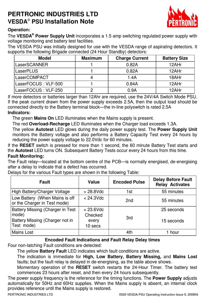
High Charger Voltage > 28.8 V 1st 20 seconds
Low Battery Voltage (In auto-test
mode, or when mains absent)
Low Charger Voltage
< 24.3 V
2nd 20 seconds
Battery Capacity Failure or
Battery Absent
< 23.6 V 3rd 30 – 40 seconds
Mains Lost 4th Aus: 55 minutes
NZ: no fault if battery OK
Reset Switch Operation
The Reset Switch is mounted on the PSU Control Board. It provides the following functions:
A momentary press resets and restarts the 24-hour timer and clears any fault conditions indicated
by the Battery Fault LED. The next one-hour battery capacity test will start 23 hours after reset, and
then it will recur at 24 hour intervals.
Pressing the Reset switch for at least 2 seconds starts the one-hour battery capacity test
immediately. The Auto Test LED lights up during the test.
With the power supply in Auto-Test mode, pressing the Reset switch for about half a second
cancels the one-hour battery capacity test. The next battery test will then start 23 hours from this
time. This provides a method of checking that the batteries are properly connected. Start the test
by pressing the Reset switch for at least two seconds. If the Auto Test LED lights up, and the
Battery Fault LED does not, then the batteries are connected and working properly.

Other Pertronic Power Supply manuals

Pertronic VESDA LaserSCANNER Quick start guide

Pertronic

Pertronic VESDA LaserSCANNER Quick start guide

Popular Power Supply manuals by other brands

Eaton Powerware Prestige Series 1500 VA Installation and operator's manual

Eaton

Eaton Powerware Prestige Series 1500 VA Installation and operator's manual

Pulsar HPSB 11A12E manual

Pulsar

Pulsar HPSB 11A12E manual

PowerBox Camtec OSW00301 quick start guide

PowerBox

PowerBox Camtec OSW00301 quick start guide

Thermaltake Toughpower XT TPX-575M user manual

Thermaltake

Thermaltake Toughpower XT TPX-575M user manual

I-Tech IT6900 Series user manual

I-Tech

I-Tech IT6900 Series user manual

RD DPS3012 installation instructions

RD

RD DPS3012 installation instructions

AimTTi MX100T instruction manual

AimTTi

AimTTi MX100T instruction manual

Powerten P60 Series Operation manual

Powerten

Powerten P60 Series Operation manual

Videotec IRHPS instruction manual

Videotec

Videotec IRHPS instruction manual

Beckhoff PS1011-2410-0000 installation manual

Beckhoff

Beckhoff PS1011-2410-0000 installation manual

Aervoe Sierra Wave EnerPlex 9700 operating instructions

Aervoe

Aervoe Sierra Wave EnerPlex 9700 operating instructions

Kramer VS-3232DN Installation

Kramer

Kramer VS-3232DN Installation

Veeco MPS-3000 CE Technical manual

Veeco

Veeco MPS-3000 CE Technical manual

MAKELSAN AG-SD-36 user manual

MAKELSAN

MAKELSAN AG-SD-36 user manual

PeakTech 1885 Operation manual

PeakTech

PeakTech 1885 Operation manual

CAMBRIONIX ModIT-MAX user manual

CAMBRIONIX

CAMBRIONIX ModIT-MAX user manual

Extron electronics PS 1230 installation guide

Extron electronics

Extron electronics PS 1230 installation guide

Elektro-Automatik PS 9040-40 2U operating guide

Elektro-Automatik

Elektro-Automatik PS 9040-40 2U operating guide

manuals.online logo
manuals.online logoBrands
  • About & Mission
  • Contact us
  • Privacy Policy
  • Terms and Conditions

Copyright 2025 Manuals.Online. All Rights Reserved.