Petroline-A OK-150 User manual

Rev.01
2024
ANNUNCIATOR OK-150
Operation Manual
PLA150.215.015.000 RE
This Manual provides information for service personnel how
to perform installation, commissioning and maintenance of
the Annunciator OK-150 (hereinafter referred to as the OK-
150).
The
OK-150
exploitation is allowed to be used by personnel
who has studied this manual, set of exploitation
documentation and passed safety training.
The OK-150 is intended to actuate audible and visual alarms
by the signals from external equipment.This device is made as
part of the DEL-150 Drilling and Well Workover Monitoring
System (hereinafter referred to as the DEL-150).
Scope of application is explosive zones of premises and
outdoor facilities according to Ex-marking. The OK-150 is
manufactured in accordance with the requirements of ISO
9001:2015.
In order to exclude the possibility of mechanical damage,
violation of electroplating and paint coatings, the rules of
storage and transportation of the device should be observed.
When studying the rules of operation, it is also necessary to
be guided by the technical description and operating
instructions of the DEL-150 System.
The OK-150 is made in a rectangular aluminum enclosure
(See Fig. 1) with a degree of IP65 protection. There are
printed circuit boards with an electronic control circuit inside.
A cable gland or fitting depending on the required
configuration for external connections is installed on the
enclosure. The boards are mounted on the bottom of the
enclosure and secured with screws. The upper part of the
enclosure is covered with a lid. A sound emitter and light
indicators are fixed on the lid. The lid is attached to the
enclosure by 4 screws, there is a sealing gasket between the
enclosure and the lid.
1. Technical Characteristics
Name of parameter
Value
Sound level, dB
105*
Nominal modulation frequency range, kHz
3…3.4
Number of LEDs
2
Maximum input voltage, VDC
30
Maximum input current, A
0.5
Power supply, VDC
12
Current consumption (at 12 VDC), A
0.15
Ex marking, EAC
1ExibIIAT5GbX
Ingress protection
IP65
Ambient temperature range,
°С
-40…+65
Dimensions, mm
116 x 66 x 64
Weight, kg
0.6
Service life, min., years
10
* at the nominal modulation frequency
1. Enclosure;
2. Cable gland or fitting;
3. First threshold LED;
4. Second threshold LED;
5. Sound emitter
Figure 1. The OK-150 components
2. Explosion Safety During Operation
Explosion protection is provided by an intrinsically safe
electrical circuit (“i”type of explosion protection).
3. Requirements for Keeping Equipment Specifications
that Cause its Explosion Safety
During operation, it is forbidden to break the seals and open the
OK-150 enclosure.
When the MU-150 / MU-150E / MK-140 unit of the DEL-150

Rev.01
System or MK-140(GAZ) Commutation Module is switched on,
it is forbidden to connect and disconnect cables, power cable
and grounding conductors. In case of malfunctions, it is
necessary to turn off the MU-150 / MU-150E / MK-140 / MK-
140(GAZ) unitand disconnect the power cable from the power
source. Then replace the faulty OK-140 with a serviceable one
by connecting it according to the documentation.
During operation, check the condition of communication
cables periodically. If a violation of the protective layer on the
cable lines is detected, replace the damaged cable
immediately.
Do not allow sealing violations. If a damage is detected,
replace the faulty equipment.
Ensuring explosion safety during operation is according to the
safety regulations, applicable to the equipment with which (or
as part of which) the equipment is used.
ATTENTION!!! During operation, it is
necessary to monitor the equipment status
and its cables. In case of any mechanical
damage of the equipment or any of the
cables connected, further operation is
strictly prohibited!
4. Installation
NOTIFICATION. Installation and further
commissioning of the equipment should be
carried out only by qualified specialists.
Before installing the OK-150, it is necessary to make sure that:
•Basic dimensions at theprocessing facilities correspond to the
dimensions of the OK-150 (see Fig. 2);
•Fixing bolts and screws are present;
•There is no damage of the connector insulation;
•There is no external damage of the components;
•There is no damage of the insulation of the signal cable.
Figure 2. Overall dimensions of the OK-150 with
mounting plate
Disregard of this instruction may lead to a serious failure of
the OK-150.
Installation is carried out in the following order:
1. Place the OK-150 annunciator so that the LEDs are
visible and the sound emitter is not closed;
2. Run and connect the commutation cable to the MU-150 /
MU-150E / MK-140 unit of the DEL-150 System or to the
MK-140(GAZ) Commutation Module through cable
channels or places not exposed to mechanical action.
5. External Electrical Connections Installation
The commutation cables for connecting of the OK-150 to the
MU-150 / MU-150E Control Modules, to the MK-140 and to the
MK-140(GAZ)CommutationModulesaredifferent.Itisrequired
to check cable’s part number before connection. At the same
time the 5-pin connector of the OK-150 is universal, and
connection is possible only to the corresponding 5-pin
connector on the MU-150 / MU-150E / MK-140 / MK-
140(GAZ) unit (See Fig. 3, 4, 5).
Figure 3. Drawing of the OK-150 and 4-pin plug for
connection to the MU-150 / MU-150E / MK-140 unit
Figure 4. Drawing of the OK-150 and 4-pin plug for
connection to the MK-140(GAZ) Commutation Module
Figure 5. Drawing of the OK-150 and 5-pin plug for
connection to the MU-150 / MU-150E / MK-140 / MK-
140(GAZ) unit

Rev.01
SENSORS
INDICATORS
BLOCKERS
BLOCKERS STATUS
BLOCK-D [080] --
BLOCK-R [081] SB
BLOCK-P [082] --
BLOCKER CHECK
POLL STOPED . . .
BLOCKER ON
BLOCKER CHECK
POLL STOPED . . .
BLOCKER ON
CHECK COMPLETED
HOOK LOAD * 95.4
FULL HOOK LOAD *105.4
BLOCK HEIGHT 0.4
TRIP VELOCITY 0.0
The cable from the OK-150 is connected to the “Horn”
connector of the MU-150 / MU-150E / MK-140 / MK-
140(GAZ) unit (see Fig. 6).
Figure 6. The MU-150 / MU-150Е/ МК-140 / MK-140(GAZ)
unit’s connector “Horn” for the OK-150 connection
6. The OK-150 Functional Test
For functional test of the OK-150 it is necessary to connect the
annunciator to the MU-150 / MU-150E / MK-140 unit, to turn
power on and proceed according the instruction below.
ATTENTION!!! The OK-150 test should be
carried out only during the work provided
according to periodic equipment check-up
and maintenance. Exclude unauthorized
disconnection or activation of
technological equipment!
Enter the setting mode using the MU-150’s keyboard (see Fig.
7).
Figure 7. The MU-150 Control Module keyboard
Proceed in the following order to reach out required blocker:
1. Unblock the keyboard by pressing +
simultaneously;
2. Use , and to enter
CONNECTED SENSORS. To return to the previous
menu, use .
+
Sensors scanning is
stopped, the blocker
check mode is turned
on, in which the OK-
150 is activated and
the relay also
changes its state.
The detailed
information is
referred in the DEL-
150 System
Operation Manual
7. Functionality Issues
Iftheaudibleandvisualalarmsareabsentincaseofexceeding
of the threshold that are set for controlled parameter (See Fig.
8), it is necessary to carry out actions in the following order:
Figure 8. Examples of exceeding parameters
1. Checking of the integrity of the commutation cable;
2. Checking of the integrity of the OK-150 plug;
3. Checking of the voltage presence on the OK-150 plug’s
connectors in the blocker check mode;
4. Checking of the OK-150 settings;
5. Replacement of the OK-150;
6. Replacement of the MU-150 / MU-150E / MK-140 / MK-
140(GAZ) unit.
8. Setting of the OK-150 Audible and Visual Alarms
The frequency of the light indication and sound modulation of
the piezoelectric element is adjusted by switches on the

Rev.01
printed circuit board of the OK-150 annunciator.
To access the switches (see Fig. 9), it is necessary to unscrew
4 screws and open the top cover with LEDs and a sound
emitter.
Figure 9. The OK-150’s switches
Light indication modes:
C // @lights constantly
T1 // @flash F=1 Hz
T2 // @flash F=2 Hz
Sound emitter modes:
SND1 // @ramp: mod = 800…1000 Hz F=1 Hz
SND2 // @ramp: mod = 3000…3400 Hz F=7 Hz
SND3 // @ramp: mod = 3000…3400 Hz F=1 Hz
SND4 // @square: mod = 3000/3400 Hz F=2 Hz
SND5 // @square: mod = 1000/0 Hz F=1 Hz
SND6 // @square: mod = 800/1000 Hz F=1 Hz
SND7 // @square: mod = 800/1000 Hz F=2 Hz
SND8 // @ramp: mod = 800…1000 Hz F=8 Hz
SND9 // @square: mod = 800/1000 Hz F=2 Hz
SND10 // @square: mod = 3400/3400 Hz F=1 Hz
Control inputs description:
[S1:S0:GND]
[+] –input connected to GND
[-] –input disconnected from GND
[*] –any state
[x] –off
DIP Description –mode switch:
[L2:L1:L0] - [B2:B1:B0] - [M1:M0]
1
lower switch position
1
upper switch position
Selection of operating modes:
[M1:M0]
7 8
Mode 1 "KEY1"
7 8
Mode 2 "KEY2"
7 8
Mode 3 "SOFT"
7 8
Mode 4 "TEST"
Mode 1 "KEY1" –compatibility with the MU-150 / MU-150E
unit with 4-pin “Horn” connector
The mode in which the control signal “S0” is closed
programmatically by default, and control occurs by the control
signal “S1”, which is closed to “GND” (see Fig. 10).
In case of connection according to drawing on Fig. 3
(connection to the MU-150 / MU-150E / MK-140 unit), the
control signals are closed directly in the OK-150 annunciator,
sound and LED control does not occur. When power is
supplied, the LEDs and the sound alarm will work
simultaneously, in accordance with the modulation and
frequency set by the switches.
In case of connection according to drawing on Fig. 4
(connection to the MK-140(GAZ) Commutation Module), the
control signal “S0” is closed directly in the OK-150
annunciator, and sound control occurs by closing the control
signal “S1” to the contact “GND” via the relay of the MK-
140(GAZ) Commutation Module, and LED control is not
happening.
Figure 10. The OK-150’s switches in the “KEY1” mode
Examples of switches settings:
•When power is supplied to the OK-150, the first threshold
LED lights with a frequency of T1 (1 Hz), the second
thresholdLEDlightswitha frequencyofT2(2Hz),the sound
is played two-tone (800/1000 Hz) with rectangular
modulation and with a frequency of 1 Hz (SND6//@square:
mod = 800/1000 Hz F=1 Hz):

Rev.01
•When power is supplied to the OK-150, the first threshold
LED lights with a frequency of T1 (1Hz), the second
threshold LED lights constantly, the sound is played
monotone (1000 Hz) with rectangular modulation and with a
frequency of 1 Hz (SND5//@square: mod = 1000/0Hz F=1
Hz):
Mode 2 "KEY2" –compatibility with the MU-150 / MU-150E
unit with 5-pin “Horn” connector
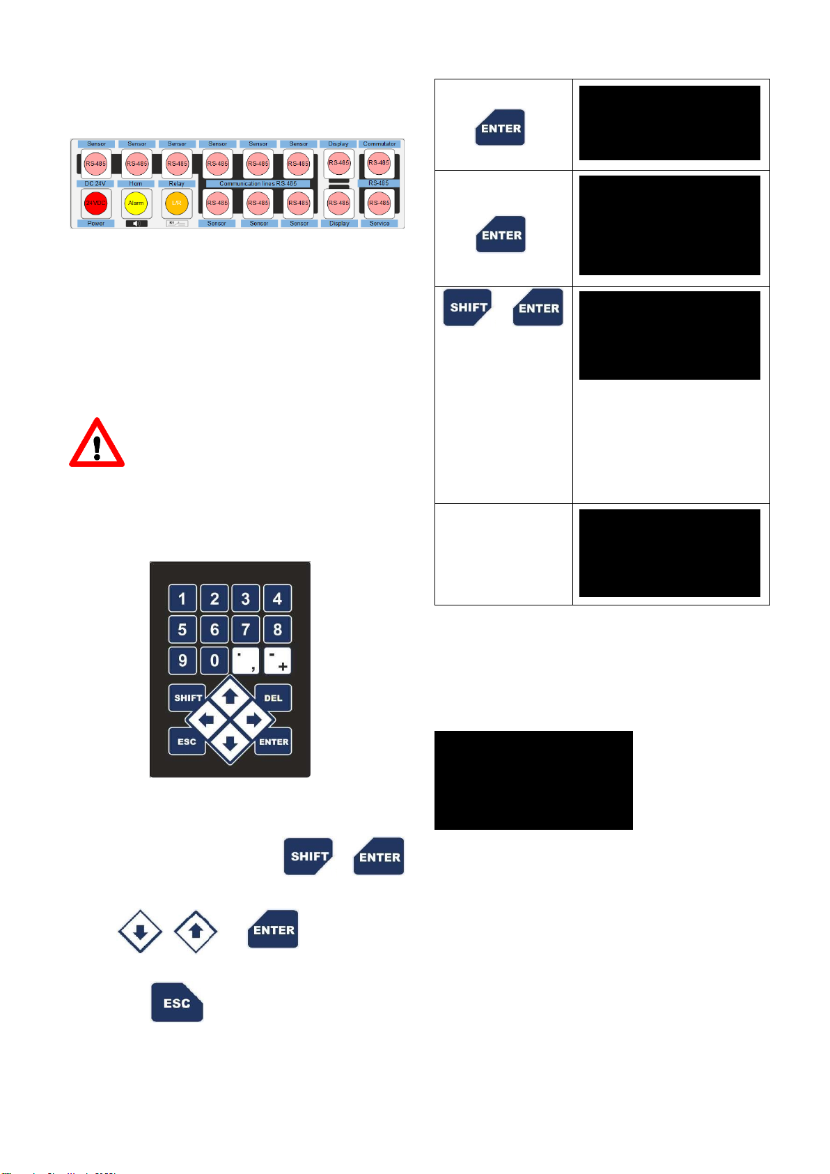
The mode in which control occurs by the both “S0” and “S1”
control signals closing them to “GND" (see Fig. 11).
Figure 11. The OK-150’s switches in the “KEY2” mode
In case of connection according to drawing on Fig. 5,
(connection to the MU-150 / MU-150E / MK-140 / MK-
140(GAZ) unit), it becomes possible to control the LEDs
separately, according to the first and second thresholds, as
well as to reproduce a different sound for each threshold.
When power is supplied, the LEDs and the sound alarm will
briefly work, subsequently, with an interval of 1 time per
minute, both LEDs light up briefly, signaling normal operation.
When the control signal “S0” is closed to “GND”, the first
threshold LED and the sound signal corresponding to the first
control signal will work, and when the control signal “S1” is
closed to “GND”, the second threshold LED and the
corresponded sound signal will be engaged in accordance
with the modulation and frequency set by the switches.
Additionally, in the "KEY2" mode there are priorities by input
signals. For example, the operation of LEDs by prioritymeans
that when the control signal “S1” is switched, the previously
activated LED light mode by the control signal “S0” will turn off
and the light mode will be turned on according to the control
signal “S1”.
Examples of switches settings:
•When power is supplied tothe OK-150and the control signal
“S0” is working, the first threshold LED lights constantly, the
sound is played two-tone (800/1000 Hz) with rectangular
modulation and with a frequency of 2 Hz (SND7//@square:
mod = 800/1000 Hz F=2 Hz). When the control signal “S1”
appears, the first threshold LED lights constantly, the
second threshold LED lights constantly, the sound is played
two-tone (800…1000 Hz), with attenuating-increasing
modulation, with frequency 8 Hz (SND8//@ramp: mod =
800...1000 Hz F=8 Hz):
•When power is supplied tothe OK-150and the control signal
“S0” is working, the first threshold LED lights with a
frequency of T1 (1 Hz), the sound is played two-tone
(3000...3400 Hz), with attenuating-increasing modulation,
with a frequency of 1 Hz (SND3//@ramp: mod = 3000...3400
Hz F=1 Hz). When the control signal “S1” appears, the first
threshold LED lights with a frequency of T1 (1 Hz), the
second threshold LED lights with a frequency of T2 (2 Hz),
the sound is played two-tone (3000/3400 Hz), with
rectangular modulation, with a frequency of 2 Hz
(SND4//@square: mod = 3000/3400 Hz F=2 Hz):
Mode 3 "SOFT”
This mode is configured via serial communication using the
program “Platone” or “ThunderFlash” and is needed to select
a specific mode of operation. The program and operating
instructions are available on request.
Mode 4 "TEST”
Cyclic check of light and sound alarm.
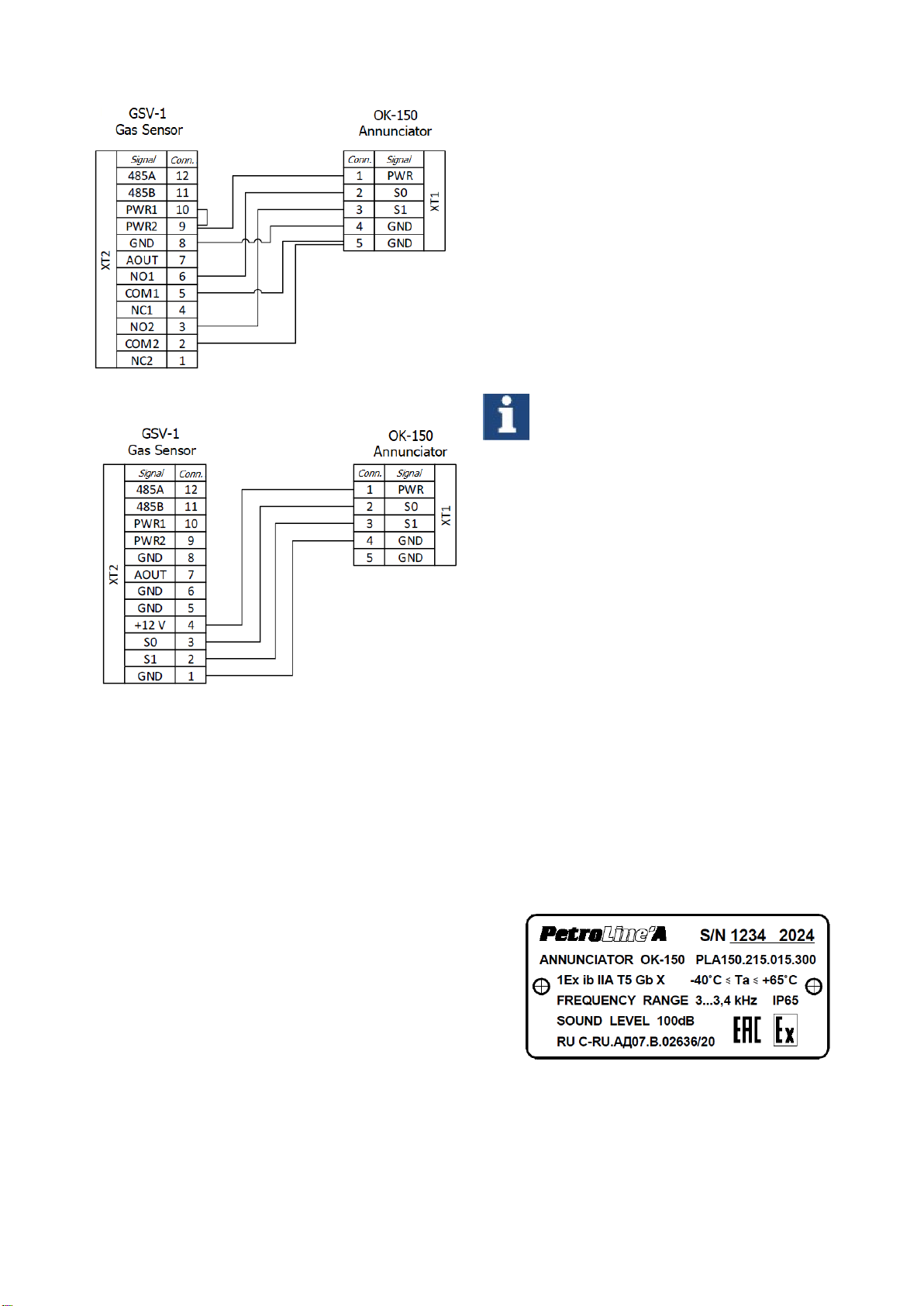
9. Setting of the OK-150 for Operation as a Part of the
GSV-1 Post
To operate the OK-150 annunciator connected to the GSV-1
gas sensor directly and display each threshold with the
corresponding visual and audible alarm, it is necessary to
switch the annunciator over to the Mode 2 "KEY2" and to
connect it to the GSV-1’s connector according to the drawings
on Fig. 12 or 13, depending on the gas sensor’s connector.

Rev.01
Figure 12. Connection of the OK-150 to the GSV-1 with
common terminal
Figure 13. Connection of the OK-150 to the GSV-1 with
special terminal
10.List of Critical Failures and Possible Issues in
Maintenance Leading to Equipment Failures and
Actions to Prevent these Failures (troubleshooting)
Incorrect set maximum values for parameters can lead to
incorrect operation of the external controlled equipment if the
maximum level for the controlled parameter is exceeded.
A short circuit or a break circuit in the power cable of the
annunciator, may cause loss of communication. The failure
can be recognized by audible and visual indication absence
in case of exceeding of the threshold that are set for controlled
parameter. Also, absence of periodic blinking of LEDs in the
Mode 2 "KEY2" is the feature of failure.
In case of failure of the OK-150 or Control Module, it is
necessary to check the equipment technical condition
according to the Clause #7 of this Operation Manual. If
troubleshooting did not lead to proper operation, it is
necessary to stop operation and replace with obviously
serviceable equipment. Defective equipment should be sent
for repair to the manufacturer or to the specialized authorized
service center.
In case of failures that can lead to emergency situations, it is
necessary to replace the equipment that has failed. If
necessary, disable additional external devices.
11.Maintenance Procedure
Maintenance is carried out in the following order:
1. Cleaning the annunciator’s enclosure from contamination;
2. Checking the safety of seals (if available);
3. Checking the presence and strength of the mounting
components;
4. Cleaning of connectors and terminals from contamination;
5. Checking for the absence of visible mechanical damages;
6. Replacement and (or) repair of damaged cable products;
7. Replacement of damaged connectors.
The contacts of the connector should be washed with an
alcohol-gasoline mixture (need 3 ml.) using a soft brush.
Connectors after cleaning and drying should be treated with
Vaseline or similar lubricant. It is recommended to treat the
threads on the connectors with graphite grease.
NOTIFICATION. Absence of maintenance
records in the passport (section
"Maintenance Records") ENTAILS
VIOLATION OF THE OPERATION RULES,
and the manufacturer has the right to
withdraw from warranty obligations
12. Limit Conditions Parameters
In case of severe mechanical damage, leakproofness
violations, seals violations, heating of parts to unacceptable
temperatures, supply of unacceptable currents and voltages,
change of calibration data, further use is unacceptable or
impractical, or restoration of its serviceable or operable
condition is impossible or impractical.
13. Marking and Packaging
The OK-150’s nameplate includes the following components
(see Fig.14):
1. Trademark or name of manufacturer;
2. Part number;
3. Name and model;
4. Serial number;
5. Manufacturing year;
6. Explosion protection marking together with certificate
number;
7. Technical characteristics.
Figure 14. Example of the OK-150 marking
Other data required by regulatory and technical
documentation may also be reflected on the nameplate.
Boxes made of plywood with metal handles for carrying are used
to transport the OK-150 as part of the DEL-150 System.

Rev.01
14.List of Components
Full completeness is indicated in the passport for equipment
released by manufacturer.
15.Repair
Repair of the OK-150 is carried out at the manufacturer or at
a specialized authorized service center.
NOTIFICATION. Absence of repair records
in the passport (section "Repair Records")
ENTAILS VIOLATION OF THE OPERATION
RULES, and the manufacturer has the
right to withdraw from warranty
obligations
16.Storage
The equipment requires careful handling, storage in dry,
clean rooms with a constant temperature from +10°C to
+35°C as an optimum range and a relative humidity of no
more than 80%. Daily temperature fluctuations should not
exceed 5°C.
The long-term storage requires conservation, according to
the requirements of the equipment conservation instructions.
The equipment arriving at the warehouses in the
manufacturer's containers are not unpacked, packed on flat
pallets and stacked or in the cells of the racks.
Factory-sealed devices are not allowed to be opened in
warehouses.
Small devices and devices arriving in individual packaging
are stored in box pallets with installation in a stack.
Devices and components without individual packaging should
be stored in shelving cells no more than 3 rows in height with
the use of cushioning materials between them.
Small devices and products arriving without packaging can
be stored in small-cell racks and cabinets, while devices or
products of the same type should be stored in one cell.
NOTIFICATION. Absence of storage records
in the passport (section "Storage Records")
ENTAILS VIOLATION OF THE OPERATION
RULES, and the manufacturer has the right
to withdraw from warranty obligations
17.Transportation
Transportation of the equipment is allowed by all types of
closed transport. The OK-150 in a package for transportation
allows the impact of transport shaking with an acceleration of
30 m/s2with a frequency of 100 beats per minute or 1500
beats with that acceleration.
18.Disposal
The OK-150 is disposed of in accordance with the
requirements and norms applicable in the oil and gas
industry.
19.Warranty Obligations
The warranty period is 12 months from the date of sale.
A full description of the warranty obligations is described in
the equipment passport.
RPE Petroline-A LLC
Address: 53АLermontova St., Naberezhnye Chelny,
Republic of Tatarstan, Russian Federation, 423801
Postal address: P.O. Box 23, 423801
Phone/Fax: +7 (8552) 535-535, 71-74-61
Popular Security System manuals by other brands

Teknim
Teknim PARS Series Installation and programming manual

Dwyer Instruments
Dwyer Instruments BDPA Series Installation and operating instructions

VENTCROFT
VENTCROFT Meditell 2 User's operation guide

Essence
Essence Care@Home C7000 Getting started

SICK
SICK deTec4 Core operating instructions

Johnson Controls
Johnson Controls PENN Connected PC10 Install and Commissioning Guide