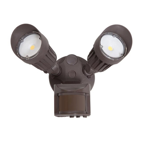
Time Setting: The base time-out value is selected by rotating the
time control dial. Rotate the control fully clockwise (CW), the time- out
will increase. Rotate the control fully counter-clockwise (CCW), the time-
out will decrease.
Ambient Light : The Ambient Light is used to keep the lights OFF if there
is already enough natural light in the room.
NOTE:
The ambient light level in the center of a room will be different from
the level at the wall where the switch is located.
Ambient Light Dial: The ambient light setting is adjusted with the
Ambient Light dial (refer to figure 2). Turning the Light Dial fully
counter-clockwise (CW), lights always turn ON when the motion is
detected, regardless of ambient light. All other settings will cause the
lights to turn ON only when the light level is less than the setting.
NOTE:
When the setting is at the minium CCW level, the lights will stay
OFF when the room is dim. When the setting is at the
maximum level clockwise(CW), the lights will turn ON when the
room is bright.
Range: To decrease detection range and sensitivity, rotate the dial
CCW (refer to figure). The detection range can be adjusted from
100% to 30%.
NOTE:
Do not set the range at the Maximum level, it may cause an error
in operation.
SETTINGS
1. With power restored and wallplate removed, remove control panel
cover. Use a small screw- driver to adjust the light sensitivity and time
setting on the device as follows:
Time Selection:
Adjust the time selector to the desired length of time the lights are to
remain ON. Lights will remain ON from 15 seconds to 30 minutes after
the room is vacated.
Rotate the control fully clockwise (CW). Lights will remain ON up
to 30 minutes.
Rotate the control fully counter-clockwise (CCW). Lights will remain
ON up to 15 seconds.
Range:
To decrease detection range and sensitivity, rotate the control CCW.
To increase detection range and sensitivity, rotate the control CW.
Light level adjustment:
To decrease the light level, rotate the control CCW.
To increase the light level, rotate the control CW.
NOTE:
If the light control is in the fully clockwise position, the lights will
turn ON whenever motion is detected, even in full daylilght. In-
termediate settings will cause the lights to turn ON only when
the ambient light is below the level selected by the light control.
2. Test that the time selection, range and light level adjustment are as
desired. If not, repeat adjustments until satisfied.
3. Replace control panel cover and mount the wallplate.
INSTALLATION IS COMPLETE.
TOOPERATE
This device operates in three modes: ON, OFF and AUTO.
ON: Slide switch to the far RIGHT.
OFF: Slide switch to the far LEFT.
AUTO: Switch is at CENTER position.
NOTES:
Allow 1 minute for this device to warm up before using in auto mode.
In AUTO mode, the device will switch lights OFF in an occupied
room if no motion is detected for the selected time delay. If continuous
operation is desired, select the ON position.
TROUBLESHOOTING
1. Lights do not switch ON when motion is detected:
Push switch to AUTO. LED should flash when motion is detected.
Motion is beyond sensing range, move closer to switch.
Adjust the light level adjustment full CW.
2. Light always stay ON:
Check that switch is in AUTO position.
Make sure no motion is occurring in the coverage area until the time
delay expires.
Check that the switch is not installed near hot air currents and heat
radiating devices, or detecting motion from an adjacent area(e.g., hall-
way traffic). If so, switch may have to be relocated.
3. Lights do not turn ON in AUTO or MANUAL ON modes:
Check that switch is installed correctly.
Check that power is ON.
Check that light bulb is functioning.
If applicable, check that switch on controlled unit is ON.
NOTE:
If problems continue, consult a qualified electrician.
Capacity Chart:
Cat. NO.
ONE YEARWARRANTY
Maxxima extends a 1 year limited warranty to the original
purchaser that the products listed are free from defects in materials
and/or workmanship only. Maxxima will replace any warranted
product to the original consumer/purchaser if the product fails
because of defects due to workmanship and/or materials within the
limited warranty period. Limited warranty is not transferable and
applies to the original installation of the Maxxima product. This offer
does not constitute in any way a product guarantee and Maxxima
does not hereby assume any obligation whatsoever beyond
sending a free replacement product
Product.Replacement.Instructions
Please contact Maxxima at Panor Corporation 631-434-1200
extension 11 or fax to 631-434-1457 for instruction and or a
Return Goods Authorization (RGA) number. Products returned
must be shipped freight prepaid with the RGA number clearly
marked on the outside of the shipping carton.


