8
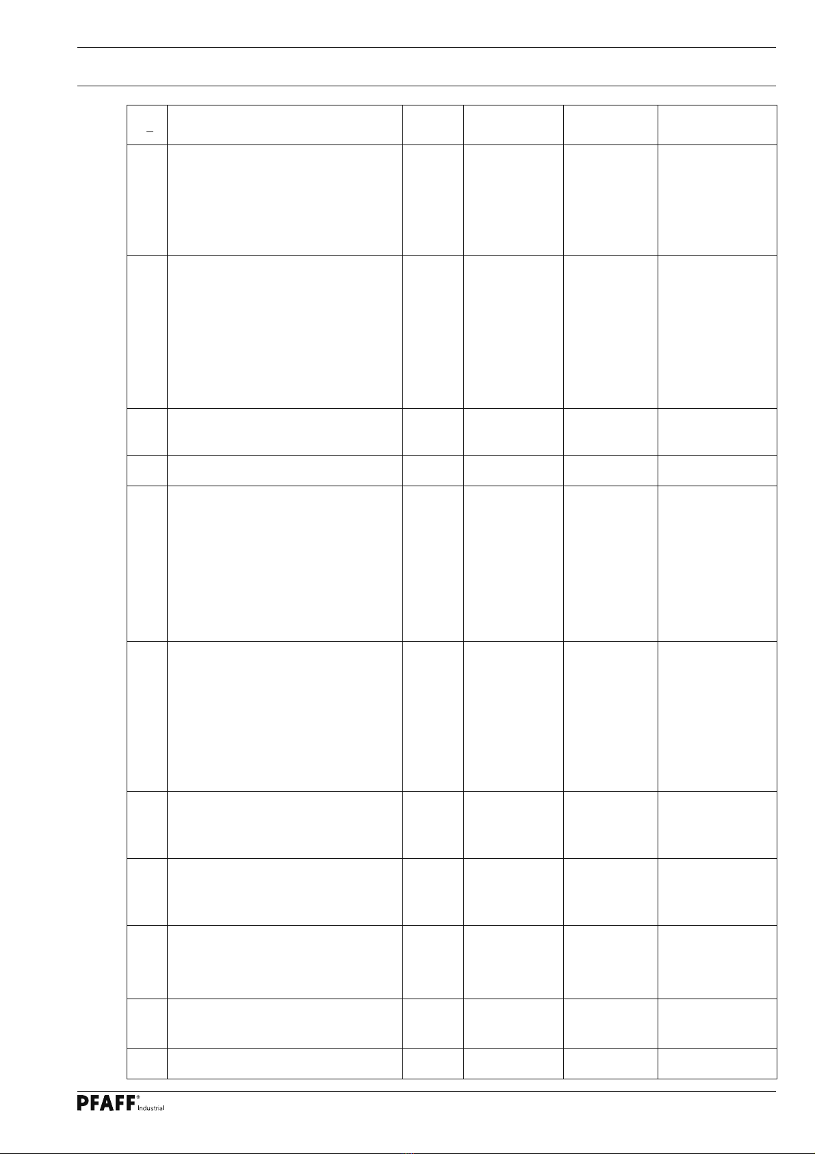
No Function User
level Setting range Set valu Machine class
584 Backtack
ON = four times , OFF = double
B,C OFF Kl. 1, 2, 3, 4, 5, 6, 7
585 Speed limitation B,C 0300 - 4800
0300 - 4800
1000
700
Kl. 1, 2, 3, 5, 7
Kl. 4, 6
586 Speed limitation B,C 0180 - 1500 600 Kl. 1, 2, 3, 4, 5, 6, 7
605 Actual speed in display (<725>)
ON = yes, OFF = no
A,B,C OFF Kl. 1, 2, 3, 4, 5, 6, 7
606 Speed: level 1 (min.) B,C 0120 - 0800 180 Kl. 1, 2, 3, 4, 5, 6, 7
607 Speed: level 12 (max.) B,C 0300 - 6000
0300 - 6000
0300 - 5500
4000
5000
3000
Kl. 1
Kl. 2, 7
Kl. 3, 4, 5, 6
608 Speed stage curve (pedal characteristic)
0 = non-linear
division of the number of speed in 12 stages
1 = 12 stages linear
2 = 24 stages non-linear
3 = 24 stages linear
4 = stages 1..8 minimum speed,
stages 9...24 linear
B,C 0000 - 0004
0000 - 0004
1
0
Kl. 1, 2, 3, 5, 7
Kl. 4, 6
609 Trimming speed 1 B,C 0100 - 0700
0100 - 0700
0100 - 0700
180
210
220
Kl. 1, 3, 4, 5, 6
Kl. 2
Kl. 7
615 End recognition when photocell goes
ON = from light to dark
OFF = from dark to light
B,C OFF Kl. 1, 2, 3, 4, 5, 6, 7
618 Inverse rotation after seam end
ON = yes, OFF = no
B,C OFF
OFF
Kl. 1, 2, 3, 4, 6, 7
Kl. 5
623 Delay in start-up time (ms) for inverse
rotation
B,C 0050 - 9000 100 Kl. 1, 2, 3, 4, 5, 6, 7
636 Thread tension release in conjunction with
presser foot
ON = yes, OFF = no
B,C OFF Kl. 1, 2, 3, 4, 5, 6, 7
642 Presser foot time from switch-on to voltage
reduction (cycling)
B,C 0010 - 0150 100 Kl. 1, 2, 3, 4, 5, 6, 7
643 Feed reverse time from switch-on to voltage
reduction (cycling)
B,C 0010 - 0150 100 Kl. 1, 2, 3, 4, 5, 6, 7
651 Presser foot with automatic descent on
machine stop. ON = yes, OFF = no
B,C ON Kl. 1, 2, 3, 4, 5, 6, 7
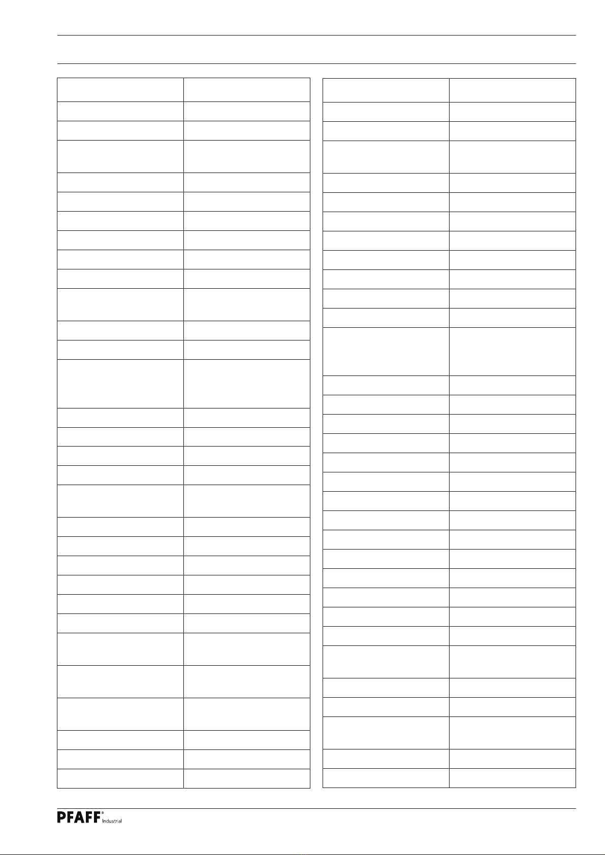
List of parameters