StepperOnline BLD-510S User manual

User
Manual
BL
D-
510S
Brushless
DC Motor
Driver
©2023 All Rights Reserved
Address: 15-4, #799 Hushan Road, Jiangning, Nanjing, China
Tel: 0086-2587156578
Web: www.omc-stepperonline.com
Sales: sales@stepperonline.com
Support: technical@stepperonline.com
Read the operating instructions carefully before putting the driver into
operation
with power
BLD-510S BLDC Driver
2
Introduction
This brushless motor driver is a driver independently developed by STEPPERONLINE to cooperate with the field of
modern industrial automatic control. It mainly uses high-performance dedicated brushless DC motor driver chips,
which have high integration, small size, complete protection, simple and clear wiring, and high reliability. The driver
is suitable for driving small and medium-sized brushless DC motors with a rated power below 200W. The driver
adopts a new type of PWM technology to make the brushless motor run at high speed, low vibration, low noise,
good stability and high reliability.
1. Features
High performance and low price
PID speed, current double loop regulator
20KHZ chopper frequency
2 times overloading capacity
Build with over-voltage, under-voltage, over-current, over-temperature, Hall signal illegal and other error alarm
functions
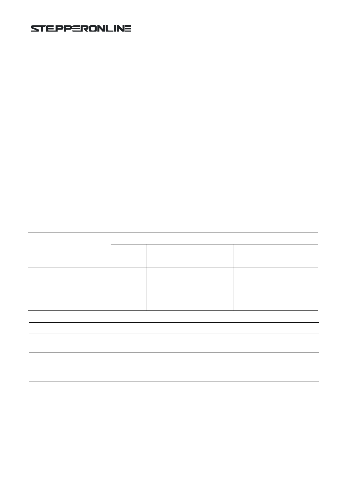
2. Specifications
2.1 Electrical Specification
Parameters
BLD-510S
Min
Typical
Max
Unit
Input voltage
24
36
48
VDC
Continuous Output Current
8.3
5.5
4.2
A
Max. Output Power
200
200
200
W
Peak Output Current
13
13
13
A
2.2 Environment
Cooling
Radiator
Control Signal
I/O
Full Isolation
Protection Functions
Over-current, overheat, over-speed, over-voltage,
under-voltage, power supply abnormality control
BLD-510S BLDC Driver
3
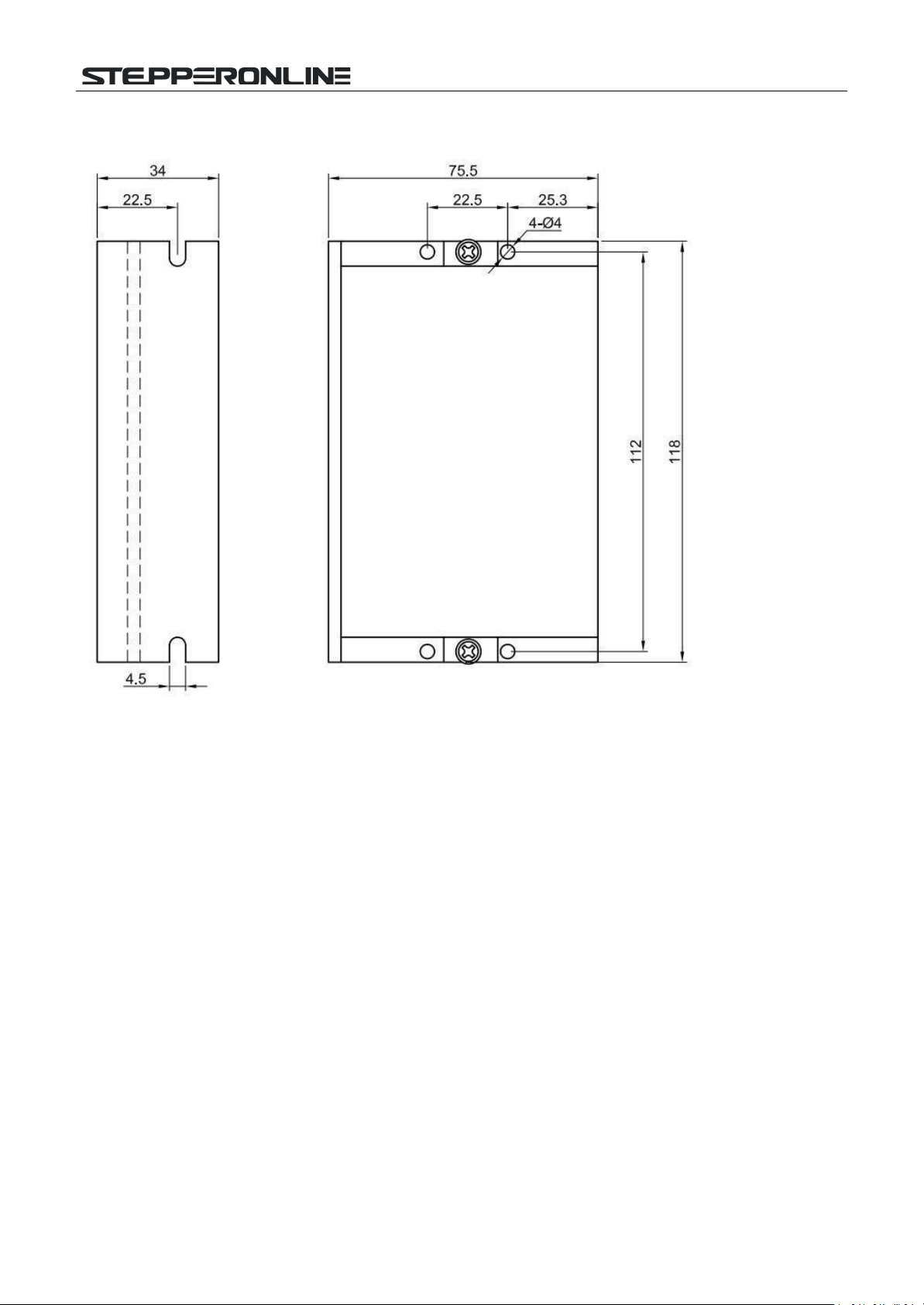
2.3 Mechanical Specification
(Unit: mm [1inch=25.4mm])
2.4 Safety Precautions
This product is professional electrical equipment and should be installed, debugged, operated and maintained by
professional
and technical personnel. Improper use will cause electric shock, fire, explosion and other dangers.
This product is powered by a DC power supply. Please confirm that the positive and negative poles of the power
supply are correct before powering on.
Do not plug or unplug the connecting cable when the power is on, and no
short-circuiting
of the cable is allowed
when the power is on, otherwise the product will be damaged.
If the motor needs to change direction while it is running, it must first decelerate till stop, and then change direction.
The driver is a power device and it is important to maintain good heat dissipation and ventilation in the working
environment.
BLD-510S BLDC Driver
4
3. Terminal Interface Description
3.1 Power Input
No.
Terminal Name
Description
1
V+
24VDC~48VDC input
2
GND
GND input
3.2 Motor Input
No.
Terminal Name
Description
1
MA
Motor A phase
2
MB
Motor B phase
3
MC
Motor C phase
4
GND
GND
5
HA
Hall signal A phase input
6
HB
Hall signal B phase input
7
HC
Hall signal C phase input
8
+5V
Hall signal power line
3.3 Control Signal
No.
Terminal Name
Description
1
GND
Signal ground
2
F/R
CW/CCW terminal
3
EN
Stop/Start terminal
4
BK
Brake terminal
5
SV
Analogy signal input terminal
6
PG
Speed output terminal
7
ALM
Alarm output terminal
8
+5V
+5V power output terminal
Built-in
potentiometer R-SL:
Adjust the motor speed gain, which can be adjusted from 0~100%.
Built-in potentiometer R-CS: Maximum protection current setting, built-in potentiometer can be set 0%~100%
continuous current protection.
4. Function and Usage
4.1 Speed Adjustment Method
The driver offers the following three speed adjustment methods, one of which can be selected by the user as follows:
Inner potentiometer speed adjustment: turn the potentiometer on the drive panel counterclockwise to reduce the
motor speed and clockwise to increase it. The potentiometer must be set to minimum when the user uses an
external input for speed adjustment.
External input speed adjustment: connect the two fixed terminals of the external potentiometer to the GND and

BLD-510S BLDC Driver
5
+5v terminals of the driver respectively, and connect the adjustment terminal to the SV terminal to adjust the speed
using the external potentiometer (10K~50K), or through other control units (e.g. PLC, microcontroller, etc.) to input the
analogue voltage to the SV terminal to achieve speed adjustment (relative to GND), the SV port accepts a range of DC
0V~+5V, corresponding to the motor rotation speed of 0~rated speed.
An external digital signal can also be used to regulate the speed: A pulse width digital signal (PWM) with amplitude of
5V and frequency of 1KHz to 2KHz can be applied between SV and GND for speed adjustment, and the motor speed is
adjusted linearly according to the duty cycle. In this case, the SV digital signal amplitude can be attenuated by
adjusting the R-SL potentiometer by a ratio of 0 to 1.0, usually by setting the R-SL to 1.0. No attenuation is applied to
the SV input digital signal.
The motor speed can also be changed by command via communication method.
4.2 Built-in
Potentiometer
Speed Control Wiring Diagram
Currently the driver has 2 versions, V2.0 and V2.4. For V2.0 Version, motor runs when the terminal is switched on and
conversely the motor stops. While for V2.4 version, motors only runs when the terminal is switched off and conversely
the motor stops.
4.3 Motor run/stop control (EN)
The motor can be controlled to run and stop by controlling the switch-on and switch-off of the terminal EN in
relation to GND. Currently the driver has 2 versions, V2.0 and V2.4. For V2.0 Version, motor runs when the
terminal is switched on and conversely the motor stops. While for V2.4 version, motors only runs when the
terminal is switched off and conversely the motor stops. When the motor is stopped using the run/stop

BLD-510S BLDC Driver
6
terminal control, the motor is stopped naturally. The law of motion is related to the load inertia.
4.4 Motor forward/reverse control (F/R)
The direction of motor operation can be controlled by controlling the connection of terminal F/R to terminal GND.
When F/R and terminal GND are not switched on, the motor runs clockwise (facing the motor shaft), and vice versa,
the motor runs
counterclockwise.
To avoid damage to the drive, when changing the motor steering, the motor should
be stopped before operating to change the steering. Changing the direction of operation while the motor is running
should be avoided.
4.5 Braking Stop (BK)
The braking stop of the motor can be controlled by the connection of control terminal BK to terminal GND. When
control terminal BK is disconnected from terminal GND, the motor runs, when it is switched on the motor quickly
brakes to a stop, braking stop is faster than natural stop, the specific stopping time is related to the load inertia of the
user's system.
Attention: As the brake stop has a bad impact on both the electrical and the mechanical, a natural stop should be
used if there are no special stopping requirements.
4.6 Motor Speed Signal Output (PG)
The speed pulse output is a 5V pulse output, to obtain the signal a pull-up resistor of 3K ohm ~10K ohm should be
connected to the power supply. The number of output pulses per revolution of the motor is 3 x N, N being the
number of pairs of poles of the motor. For example: 2 pairs of poles, i.e. a four-pole motor, 6 pulses per revolution.
When the motor speed is 500 rpm, the output pulse of the terminal PG is 3000.
4.7 Alarm Output (ALM)
Alarm output of the driver: this terminal is low during an alarm. To obtain a signal, a pull-up resistor of 3K ohm to
10K ohm should be connected to the power supply. When the alarm is on, this terminal is connected to GND (low
level) and the driver stops itself and is in alarm.
4.8 Driver Failure
If a fault occurs inside the driver such as overvoltage or overcurrent, the driver enters a protection state, the driver
will
automatically
stop working, the motor stops and the red light on the driver is always on. The driver can only
disarm the alarm if the enable terminal is reset (i.e. EN is disconnected from GND) or if power is cut off. Please check
the motor wiring or remove the load if this fault occurs.

BLD-510S BLDC Driver
7
4.9 Connection Diagram of Brushless Motor and Driver
4.10 Sensorless control mode
STEPPERONLINE drivers can be used for sensorless brushless motors.
But it should be noted that since our brushless driver is mainly used for our brushless motor with sensors, its built-in
program is also used for motors with sensors.
Although our brushless driver can be used for sensorless brushless motors, the program of the driver is not fully
compatible and can only be used in simple scenarios. Our brushless drives are not recommended if the motor needs to
be started and stopped frequently.
When using a brushless driver to drive a sensorless motor, it is necessary to use software to set the sensorless starting
torque according to the parameters of the motor.

BLD-510S BLDC Driver
8
5. Communication Method
The communication mode uses the standard Modbus protocol, which complies with the national standard GB/T
19582.1-2008. It uses a dual-line serial communication based on RS485, and the physical interface adopts a
conventional 3-pin 2.54 wiring terminal (A+, GND, B-) which is easy to connect in series. The transmission mode is
RTU, and the verification mode is CRC, with the CRC starting word being FFFFH. The data mode is 8-bit asynchronous
serial, with 1 stop bit and no parity bit. It supports multiple communication speeds (see parameter table for details)
Function parameter support 03H multi-register read, 06H single register write.
Site address: 00: Broadcast address
1-250: User address
251-255: Special address, not available to users

BLD-510S BLDC Driver
9
No.
Addre
ss
Name
Setting Range
Defau
lt
Uni
t
00
$8000
First byte: control bit state
Second byte: Hall angle
and number of pole pairs
of motors
First byte: Bit0: EN
Bit1: FR
Bit2:BK
Bit3: NW
NW=1: 485 control start stop
speed regulation,
NW=0: External IO control
start/stop, analog to adjust
speed Bit4: MDX(invalid)
Bit5:
X12(invalid)
Bit6: KH
Second byte:
Bit0-3: number of pole pairs 1-15
Bit4-7: hall angle 0:120
00H
04H
01
$8001
Maximum speed for
analogue speed
regulation
0-65535
6000
RPM
Jumper cap control
02
$8002
First byte: start torque
Second byte: sensorless
start speed
1-255
1-255
40H
04H
03
$8003
First byte: acceleration
time Second byte:
deceleration time
1-255
0
0
0.1s
04
$8004
First byte: maximum
current
Second byte: model
90H
0FH
144 corresponds
to 13A
15 Sensored,
16: Sensorless
05
$8005
Communicati
on speed
setting
Closed loop: 0-65535
Open loop: 0-255
2000
81%
RPM
06
$8006
Braking force
0-1023
1023
07
$8007
First byte: site address
Second byte: reserve
1-250
1
0
10-17
$8010-$8017
Reserved
18
$8018
Actual motor speed
Return value
hexadecimal to
decimal
multiplied by 20
divided by the
number of motor
poles
1B
$801B
First byte: fault state
Second byte:
motor running state
Bit0: Locked rotor
Bit1: Over-current
Bit2: Hall value
abnormal Bit3: Bus
voltage too low Bit4:
Bus voltage too high
Bit5: Current peak
alarm Bit6: Reserved
Bit7: Reserved
1C
$801C-$801F
Reserved
20
Over $8020 illegal
BLD-510S BLDC Driver
10
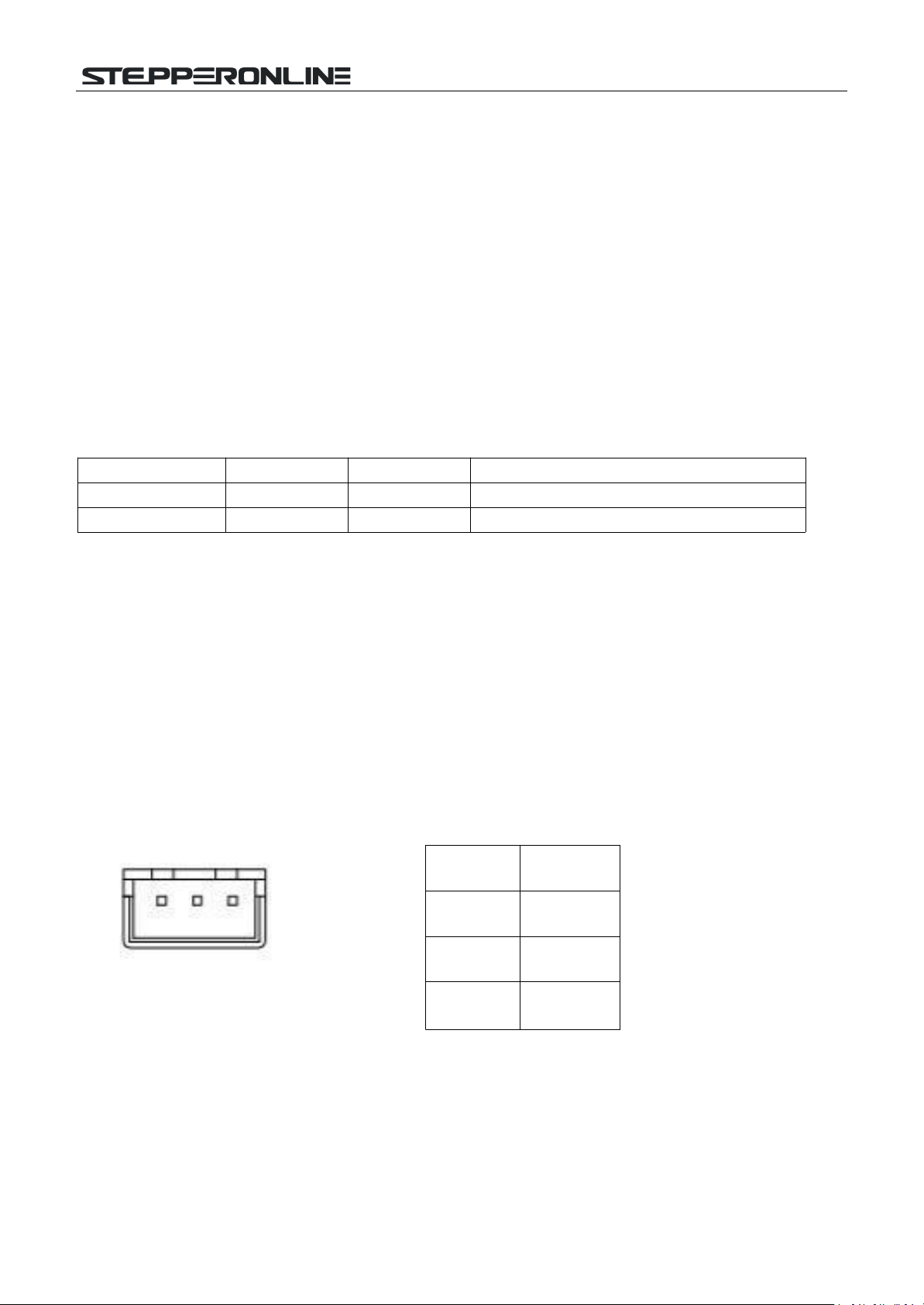
Pin
Function
1
A
2
GND
3
B
Address: 8000H-8017H are read and write registers
Address: 8018H-801FH are read-only registers
Other addresses are illegal
8000: First byte:
EN: At NW=0, 0: external EN low valid 1: external EN high valid
At NW=1, 0: EN not valid 1: EN valid
FR: At NW=0,
At NW=1,
0: external FR low valid
0: FR not valid
1: external FR high valid
1: FR valid
BK: At NW=0, 0: external BK low valid 1: external BK high valid
At NW=1,
KH:
0: BK not valid
0:
Speed closed-loop
mode
1: BK valid
1:
Speed open-loop
mode
NW
MDX
X12
Function
0
0
X
External analog speed
1
X
X
Internal
communication
control
2 pole pair start 01 06 80 00 09 02 27 9B
Write speed 1000 01 06 80 05 E8 03 BE 0A
Write
speed 1500 01 06 80 05 DC 05 28 C8
Natural
stop 01 06 80 00 08 02 26 0B
Braking
stop 01 06 80 00 0D 02 25 5B
6. Communication Wiring Method
RS-485 communications can be made by driving a conventional 3-pin 2.54 wiring port device.
The pinout of the conventional 3-pin 2.54 wiring port is defined as follows:
Table of contents
Other StepperOnline DC Drive manuals

StepperOnline
StepperOnline DM556T User manual

StepperOnline
StepperOnline BLD-AC750S User manual

StepperOnline
StepperOnline BLD-550S User manual

StepperOnline
StepperOnline DM556T User manual

StepperOnline
StepperOnline BLD-530S User manual

StepperOnline
StepperOnline DM860I User manual

StepperOnline
StepperOnline CLRS Series User manual

StepperOnline
StepperOnline DM860N User manual

StepperOnline
StepperOnline CL57T User manual

StepperOnline
StepperOnline CL42T User manual


