Pfaff 3119 User manual

296-12-18 462/002
Betriebsanleitung engl. 04.01
Instruction manual
3119
This instruction manual applies to machines from the
following serial numbers onwards:
# 873444

This instruction manual applies to all versions and subclasses listed under
"Specifications".
Reprinting, copying or translation of PFAFF instruction manuals, whether in whole or in part,
is not permitted without our prior permission and not without written indication of the
source.
G.M. PFAFF KAISERSLAUTERN
INDUSTRIEMASCHINEN AG
Postfach 3020
D-67653 Kaiserslautern
Königstr. 154
D-67655 Kaiserslautern
VTD Verlag
77901 Lahr

Contents
Contents .................................................................................Chapter – Page
1Safety ........................................................................................................................... 1 - 1
1.01 Regulations ................................................................................................................... 1 - 1
1.02 General notes on safety ................................................................................................ 1 - 1
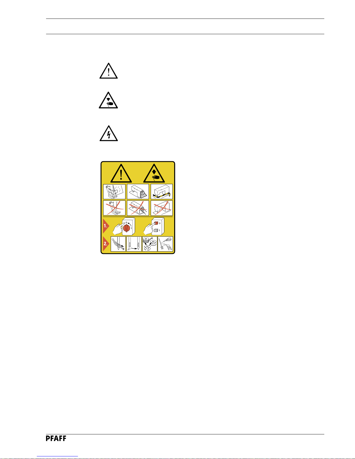
1.03 Safety symbols ............................................................................................................. 1 -2
1.04 Important notes for the user ......................................................................................... 1 - 2
1.05 Notes for operating and technical staff ......................................................................... 1 - 3
1.05.01 Operating staff .............................................................................................................. 1 - 3
1.05.02 Technical staff............................................................................................................... 1 - 3
1.06 Danger warnings........................................................................................................... 1 - 4
2Proper Use ................................................................................................................... 2 - 1
3Specifications .............................................................................................................. 3 - 1
3.01 General information....................................................................................................... 3 - 1
3.02 Stitch formations of the various sub-classes................................................................. 3 - 2
4Disposal of Machine ................................................................................................... 4 - 1
5Transportation, packing and storage......................................................................... 5 - 1
5.01 Transportation to customer’s premises ........................................................................ 5 - 1
5.02 Transportation inside customer’s premises .................................................................. 5 - 1
5.03 Disposal of packing materials........................................................................................ 5 - 1
5.04 Storage ......................................................................................................................... 5 - 1
6Explanation of symbols .............................................................................................. 6 - 1
7Controls ....................................................................................................................... 7- 1
7.01 On/off switch ................................................................................................................7- 1
7.02 Pedal ............................................................................................................................. 7 - 1
7.03 Preventing knife engagement ....................................................................................... 7 - 2
7.04 Control panel................................................................................................................. 7 - 3
8Installation and commissioning ................................................................................. 8 - 1
8.01 Installation..................................................................................................................... 8 - 1
8.01.01 Adjusting the table height ............................................................................................. 8 - 1
8.01.02 Installation variants ....................................................................................................... 8 - 2
8.01.03 Connecting the plug-type connections .......................................................................... 8 - 3
8.01.04 Fitting the reel stand ..................................................................................................... 8 - 4
8.02 Commissioning ............................................................................................................. 8 - 4
8.03 Switching the machine on / off ..................................................................................... 8 - 4
8.04 Setting up the machine control unit .............................................................................. 8 - 5
8.04.01 Establishing the sub-class ............................................................................................. 8 - 5
8.04.02 Setting parameter "202" ................................................................................................ 8 - 6
9Setting up .................................................................................................................... 9 -1
9.01 Inserting the needle ...................................................................................................... 9 - 1
9.02 Winding the bobbin thread / adjusting the preliminary thread tension........................... 9 - 2
9.03 Threading the bobbin case / adjusting the thread tension ............................................. 9 - 3
9.04 Changing the bobbin ..................................................................................................... 9 - 4
9.05 Threading the needle thread ......................................................................................... 9 - 5

Contents
Contents .................................................................................Chapter – Page
9.06 Selecting the buttonhole type ....................................................................................... 9 - 6
9.07 Adjusting the needle thread tension.............................................................................. 9 - 7
9.08 Adjusting the work clamp pressure............................................................................... 9 - 8
10 Sewing ....................................................................................................................... 10 -1
10.01 Operating panel with speed display ............................................................................ 10 - 1
10.02 Operating panel with display of the buttonhole model ................................................ 10 - 2
10.03 Selecting a buttonhole ................................................................................................ 10 - 3
10.04 Selecting the cut length of the buttonhole .................................................................. 10 - 4
11 Input ...........................................................................................................................11- 1
11.01 Summary of the function groups and parameters....................................................... 11 - 1
11.02 Selecting the function group and altering the parameters........................................... 11 - 2
11.03 Entering / altering the access code ............................................................................. 11 - 3
11.04 Allocating access rights............................................................................................... 11 - 4
11.05 Variable programs ....................................................................................................... 11 - 5
11.05.01 Copying programs....................................................................................................... 11 -5
11.05.02 Creating/modifying variable programs......................................................................... 11 - 6
11.05.03 Buttonhole models...................................................................................................... 11 -7
11.05.04 Table for recording personal variable programs........................................................... 11 -10
11.06 Special programs ........................................................................................................ 11 -12
11.07 PC-programs (optional)................................................................................................ 11 - 12
11.07.01 SAM (Sewing Application Manager)............................................................................ 11 -12
11.07.02 OSCA (On-/Offline Sewing Creativity Arrangement) ................................................... 11 -12
11.07.03 Data transfer between PC (SAM) and PFAFF 3119..................................................... 11 -13
12 Care and maintenance .............................................................................................. 12 - 1
12.01 Cleaning the machine.................................................................................................. 12 - 1
12.02 Cleaning the hook compartment ................................................................................. 12 - 2
12.03 Cleaning the air filter of air filter / lubricator................................................................. 12 - 3
12.04 Checking / adjusting the air pressure .......................................................................... 12 - 3
12.05 Oil level for the needle drive unit................................................................................. 12 - 4
12.06 Oil level for the hook ................................................................................................... 12 - 4
13 Adjustment ................................................................................................................ 13 - 1
13.01 Notes on adjusting ...................................................................................................... 13 - 1
13.02 Tools, gauges and other accessories .......................................................................... 13 - 1
13.03 Abbreviations .............................................................................................................. 13- 1
13.04 Toothed belts of hook drive unit.................................................................................. 13 - 2
13.05 Drive rods of bobbin thread trimming device .............................................................. 13 - 3
13.06 Switch for sewing start ............................................................................................... 13 - 4
13.07 Basic position of feed drive unit .................................................................................. 13 - 5
13.08 Preliminary adjustment of the work clamp.................................................................. 13 - 6
13.09 Toothed belts of the main drive unit............................................................................ 13 - 7
13.10 Preliminary adjustment of the needle height............................................................... 13 - 8
13.11 Position of the needle plate in relation to the needle .................................................. 13 - 9

Contents
Contents .................................................................................Chapter – Page
13.12 Sensor board of needle drive ( in dismantled state ) ................................................... 13 -10
13.13 Basic setting of the needle drive unit .......................................................................... 13 -12
13.14 Basic position of the work clamp
( lengthwise to the arm ) ........................................ 13 -13
13.15 Basic position of the work clamp ( crosswise to the arm ).......................................... 13 -14
13.16 Upper take-up lever position ( reference position )...................................................... 13 -15
13.17 Lifting elbow on work clamp ....................................................................................... 13 -16
13.18 Work clamp stroke...................................................................................................... 13 -17
13.19 Lifting cylinder of the work clamp ............................................................................... 13 -18
13.20 Cutting pressure of the knife unit ( in dismantled state )............................................. 13 -19
13.21 Position of the knife bracket and lower knife stop ...................................................... 13 -20
13.22 Upper knife stop ......................................................................................................... 13 -22
13.23 Knife control switch .................................................................................................... 13 -23
13.24 Knife motion................................................................................................................ 13 -24
13.25 Distance of knife to the needle bar ............................................................................. 13 -25
13.26 Changing the knife / knife height................................................................................. 13 -26
13.27 Functional test ............................................................................................................ 13-27
13.28 Needle thread cutter ( vertical and horizontal adjustment ) ......................................... 13 -28
13.29 Cam guide unit............................................................................................................ 13 -29
13.30 Needle thread cutter stroke ........................................................................................ 13 -30
13.31 Needle thread cutter switch........................................................................................ 13 -31
13.32 Needle thread cutter release....................................................................................... 13 -32
13.33 Catch........................................................................................................................... 13 -33
13.34 Swing out motion of the needle thread cutter............................................................. 13 -34
13.35 Needle bar rise and hook-to-needle clearance............................................................. 13 -35
13.36 Needle bar height and needle guard............................................................................ 13 -37
13.37 Bobbin case holder...................................................................................................... 13 -38
13.38 Hook lubrication .......................................................................................................... 13 -39
13.39 Knife position .............................................................................................................. 13 -40
13.40 Knife guard..................................................................................................................13-41
13.41 Needle thread tension release .................................................................................... 13 -42
13.42 Needle thread puller.................................................................................................... 13 -43
13.43 Side thread tension and slack thread regulator ........................................................... 13 -44
13.44 Bobbin winder ............................................................................................................. 13 -45
13.45 Retainer position (only for 3119-2/63).......................................................................... 13 -46
13.46 Carrying out a cold start .............................................................................................. 13 -46
13.47 Parameter settings...................................................................................................... 13 -47
13.47.01 Selecting and altering parameters............................................................................... 13 -47
13.47.02 List of parameters....................................................................................................... 13 -48
13.48 Error messages........................................................................................................... 13 -53
14.01 Wearing parts ............................................................................................................ 14 - 1
15.01 Circuit diagrams ........................................................................................................ 15 - 1

Safety
1 - 1
1 Safety
1.01 Regulations
This machine is constructed in accordance with the European regulations indicated in the
conformity and manufacturer's declarations.
In addition to this instruction manual, please also observe all generally accepted, statutory
and other legal requirements, including those of the user's country, and the applicable pol-
lution control regulations!
The valid regulations of the regional social insurance society for occupational accidents or
other supervisory authorities are to be strictly adhered to!
1.02 General notes on safety
●The machine must only be operated by adequately trained operators and only when the
instruction manual has been fully read and understood!
●All notices on safety and the instruction manual of the motor manufacturer are to be read
before the machine is put into operation!
●All notes on the machine concerning danger and safety must be observed!
●The machine must be used for the purpose for which it is intended and must not be
operated without its safety devices; all regulations relevant to safety must be adhered to.
●When part sets are changed (e.g. needle, presser foot, needle plate, feed dog or bob-bin),
during threading, when the workplace is left unattended and during maintenance work,
the machine must be isolated from the power supply by turning off the on/off switch or
removing the plug from the mains!
●Daily maintenance work must only be carried out by appropriately trained persons!
●Repairs and special maintenance work must only be carried out by qualified technical
staff or persons with appropriate training!
●During maintenance or repairs on the pneumatic system the machine must be isolated
from the compressed air supply! The only exception to this is when adjustments or
function checks are carried out by appropriately trained technical staff!
●Work on the electrical equipment must only be carried out by technical staff who are
qualified to do so!
●Work on parts or equipment connected to the power supply is not permitted! The only
exceptions to this are specified in regulations EN 50110.
●Conversion or modification of the machine must only be carried out under observation of
all relevant safety regulations!
●Only spare parts which have been approved by us are to be used for repairs! We draw
special attention to the fact that spare parts and accessories not supplied by us have not
been subjected to testing nor approval by us. Fitting and/or use of any such parts may
cause negative changes to the design characteristics of the machine. We shall not ac-
cept any liability for damage caused by the use of non-original parts.

Safety
1 - 2
1.03 Safety symbols
Danger!
Special points to observe.
Danger of injury to operating or technical staff!
Electric voltage!
Danger to operating or technical staff!
1.04 Important notes for the user
●This instruction manual belongs to the equipment of the machine and must be available
to the operating staff at all times.
This instruction manual must be read before the machine is operated for the first time.
●Both operating and technical staff must be instructed on the safety devices of the mach-
ine and on safe working methods.
●It is the duty of the user to operate the machine in perfect running order only.
●The user must ensure that none of the safety devices are removed nor put out of work-
ing order.
●The user must ensure that only authorized persons operate and work on the machine.
For further information please refer to your PFAFF agency.
I
Caution
Do not operate without finger guard and safety devices.
Before threading, changing bobbin and needle, cleaning
etc. switch off main switch.

Safety
1 - 3
1.05 Notes for operating and technical staff
1.05.01 Operating staff
Operating staff are the persons responsible for setting up, operating and cleaning the mach-
ine and for removing any disturbances in the sewing area.
The operating staff are obliged to observe the following points, and must:
●always observe the notes on safety in this instruction manual!
●avoid using any working methods which adversely effect the safety of the machine!
●avoid wearing loose-fitting clothing or jewelry such as necklaces or rings!
●also ensure that only authorized persons are allowed near the danger area of the
machine!
●immediately report to the user any changes to the machine that may affect its safety!
1.05.02 Technical staff
Technical staff are persons who have been trained in electrical engineering, electronics,
pneumatics and mechanical engineering. They are responsible for lubricating, servicing,
repairing and adjusting the machine.
The technical staff are obliged to observe the following points, and must:
●always observe the notes on safety in this instruction manual!
●switch off the on/off switch before carrying out adjustment and repair work and ensure it
cannot be switched on again unintentionally!
●never work on parts or equipment still connected to the power supply! Exceptions to this
are only permissible according to regulations EN 50110;
●isolate the machine from the compressed air supply when carrying out maintenance or
repair work on pneumatic equipment!
Exceptions to this are only permissible for function checks;
●replace all safety covers after carrying out maintenance or repair work!

Safety
1 - 4
56-001
1.06 Danger warnings
A working area of 1 m must be kept free both in front of and behind the mach-
ine, so that easy access is possible at all times.
Never put your hands in the sewing area during sewing!
Danger of injury by the needle!
During maintenance and adjustment work the knife must be secured with
locking device 1. Danger of injury from the knife!
Fig. 1 - 01
Do not operate the machine without the take-up lever guard 2!
Danger of injury from the movement of the take-up lever.
Do not operate the machine without eye shield 3!
Danger of injury from needle splinters! The type of eye shield is dependent on
the way the machine is installed.
Only operate the machine with cover 4closed.
Danger of injury from the hook!
56-002
4
3
2
3
1

Proper use
2 - 1
2 Proper use
The PFAFF 3119 is used for sewing purl or flat buttonholes with two flat or raised square
bars on linen and clothing.
Any use of these machines which is not approved by the manufacturer shall be
considered as improper use! The manufacturer shall not be liable for any dam-
age arising out of improper use! Proper use shall also be considered to include
compliance with the operation, adjustment, service and repair measures speci-
fied by the manufacturer!

Specifications
3 - 1
3 Specifications ▲
3.01 General information
Subclasses:
-1/51, -1/52, -2/51: ........................................................................ for sewing fine materials
-2/53, -3/51, -4/51: .......................................................for sewing medium-heavy materials
-2/63:.............................................................................. for sewing delicate knitted fabrics
Max. sewing speed:............................................................................................4200 min-1
Stitch type:.................................................................................................................... 304
Needle bar stroke:................................................................................................. 34.5 mm
Max. thickness of workpiece: ........................................................................... max. 4 mm
Max. work clamp clearance: ........................................................................ max. 12.5 mm
Fabric clearance (crosswise to sewing arm): ......................................................... 235 mm
Fabric clearance (lengthwise to sewing arm): .......................................................... 30 mm
Stitch formation: .......................................................... buttonhole, max. 48 mm x 5.5 mm
Length of buttonhole cut:...................................................................... 6.4 mm – 38.1 mm
Zig-zag stitch:................................................................................................. max. 5.5 mm
Number of stitches: ........................................................................... freely programmable
Feed type: .........................................................................................................intermittent
Power supply: .......................................190 – 240 V –20%, +10%, 50/60 Hz, single phase
Power consumption: ...................................................................................... max. 0.6 KVA
Input power rating:.................................................................................................. 0.7 kVA
Fuse protection: ............................................................................................. 1 x 16A, inert
Software status:.................................................................................. see parameter "104"
Working air pressure: .................................................................................................. 6 bar
Air consumption ..................................................................................... ~1.2 l / work cycle
Noise emission level at workplace with a sewing cycle of 4 sec.
On and 2 sec. Off:......................................................................................... LpA ≤ 81 dB(A)
( Noise measurement in accordance with DIN 45 635-48-B-1 )
Sewing head dimensions:
Length:...................................................................................................... approx. 514 mm
Width: ....................................................................................................... approx. 200 mm
Height: ...................................................................................................... approx. 450 mm
Weight of sewing head: ................................................................................. approx. 65 kg
Dimensions of base:
Length:.................................................................................................... approx. 1060 mm
Width: ....................................................................................................... approx. 600 mm
Height ....................................................................................................... approx. 820 mm
Weight of base incl. control box:.................................................................... approx. 45 kg
Needle system:............................................................................................................. 438
Needle size for fine materials:...................................................................................60 - 70
Needle size for medium-weight materials:..............................................................80 - 100
▲ Subject to alteration


Disposal of Machine
4 - 1
4 Disposal of Machine
●Proper disposal of the machine is the responsibility of the customer.
●The materials used for the machine are steel, aluminium, brass and various plastic
materials.
The electrical equipment comprises plastic materials and copper.
●The machine is to be disposed of according to the locally valid pollution control
regulations; if necessary, a specialist ist to be commissioned.
Care must be taken that parts soiled with lubricants are disposed of separately
according to the locally valid pollution control regulations!

Transportation, packing and storage
5 - 1
5 Transportation, packing and storage
5.01 Transportation to customer’s premises
All machines are delivered completely packed.
5.02 Transportation inside the customer’s premises
The manufacturer cannot be made liable for transportation inside the customer’s premises,
nor to other operating locations. Care must be taken that the machine is transported in an
upright position.To lift the machine with a suitable lifting appliance, lifting ring 1 delivered
with the machine can be screwed into the threaded hole on the machine.
5.03 Disposal of packing materials
The packing materials of these machines consist of paper, cardboard andVCE-fibre.
Proper disposal of the packing material is the responsibility of the customer.
5.04 Storage
If the machine is not in use, it can be stored as it is for a period of up to six months, but it
should be protected against dust and moisture.
If the machine is stored for longer periods, the individual parts, especially the surfaces of
moving parts, must be protected against corrosion, e.g. by a film of oil.
Fig. 5 - 01
1

Explanation of symbols
6 - 1
6 Explanation of symbols
In this instruction manual, work to be carried out or important information is accentuated by
symbols. These symbols have the following meanings:
Note, information
Cleaning, care
Lubrication
Maintenance, repairs, adjustment, service work
(only to be carried out by technical staff)

7 - 1
Controls
0
56-067
Fig. 7 - 01
1
7 Controls
7.01 On / off switch
●The machine is switched on or off by
turning the on / off switch 1.
7.02 Pedal
0= Neutral position
+1 = Work clamp lowered
+2 = Sewing
0+1
+2
Fig. 7 - 02

Controls
7 - 2
56-006
7.03 Preventing knife engagement
●By operating push button 1, knife
engagement at the end of the current
sewing cycle is prevented.
●By moving lever 2in the direction of the
arrow, the knife is mechanically locked.
This prevents knife engagement during
setting-up, maintenance and adjustment
work.
Fig. 7 - 03
1
2


8 - 1
Installation and commissioning
8 Installation and commissioning
The machine must only be installed and commissioned by qualified personnel!
All relevant safety regulations must be strictly adhered to!
If the machine is delivered without a table, be sure to use a stand and table top
that can hold the weight of the machine with its motor.
It is very important to ensure that the stand of the machine is firm and steady,
also during sewing.
8.01 Installation
The site where the machine is installed must be provided with suitable connections for
electric current.
It must be ensured that the standing surface of the machine site is firm and horizontal, and
that sufficient lighting is provided for.
For packing and transportation reasons the table top is in the lowered position.
The table height is adjusted as described below.
8.01.01 Adjusting the table height
●Loosen screws 1and 2and set the table height as required.
●Firmly tighten screw 1.
●Set the required pedal position and tighten screw 2.
Fig. 8 - 01
1
1
2
Other manuals for 3119
3
Table of contents
Other Pfaff Sewing Machine manuals

Pfaff
Pfaff 1080S User manual

Pfaff
Pfaff Creative Vision User manual

Pfaff
Pfaff 5704 User manual

Pfaff
Pfaff 3516-1/25 User manual

Pfaff
Pfaff 73 User manual

Pfaff
Pfaff 8309-023 User manual

Pfaff
Pfaff expression line User manual

Pfaff
Pfaff 433 User manual

Pfaff
Pfaff CREATIVE 4.0 - User manual

Pfaff
Pfaff expression 2.0 User manual

Pfaff
Pfaff 3734-2/01 User manual

Pfaff
Pfaff 118 User manual

Pfaff
Pfaff Embroidery Mode-Stitch-Out User manual

Pfaff
Pfaff 3586-2/02 User manual

Pfaff
Pfaff 1591 Guide

Pfaff
Pfaff 939 User manual

Pfaff
Pfaff 9083-2/99 User manual

Pfaff
Pfaff 1422-900/81 User manual

Pfaff
Pfaff 8304-040 User manual

Pfaff
Pfaff 3334 User manual