Pfaff 335 Guide

Adjustment Manual
335
296-12-18 642/002
Justieranleitung engl. 12.06
This Adjustment Manual is valid for machines from the
following serial numbers onwards:
# 2 734 226

The reprinting, copying or translation of PFAFF Service Manuals, whether in whole or in part,
is only permitted with our previous authorization and with written reference to the source.
PFAFF Industrie Maschinen AG
Postfach 3020
D-67653 Kaiserslautern
Königstr. 154
D-67655 Kaiserslautern

Index
Contents ..................................................................................Page
13 Adjustment ........................................................................................................................... 5
13.01 Notes on adjustment ............................................................................................................. 5
13.02 Tools, gauges and other accessories for adjusting ............................................................... 5
13.03 Abbreviations ......................................................................................................................... 5
13.04 Explanation of the symbols.................................................................................................... 5
13.01 Adjusting the basic machine .................................................................................................. 6
13.04.01 Lateral positioning of the feed dog ........................................................................................ 6
13.04.02 Lengthwise positioning of the feed dog ................................................................................ 7
13.04.03 Height of the bottom feed dog (only on machines with lifting phase – P-version)................. 8
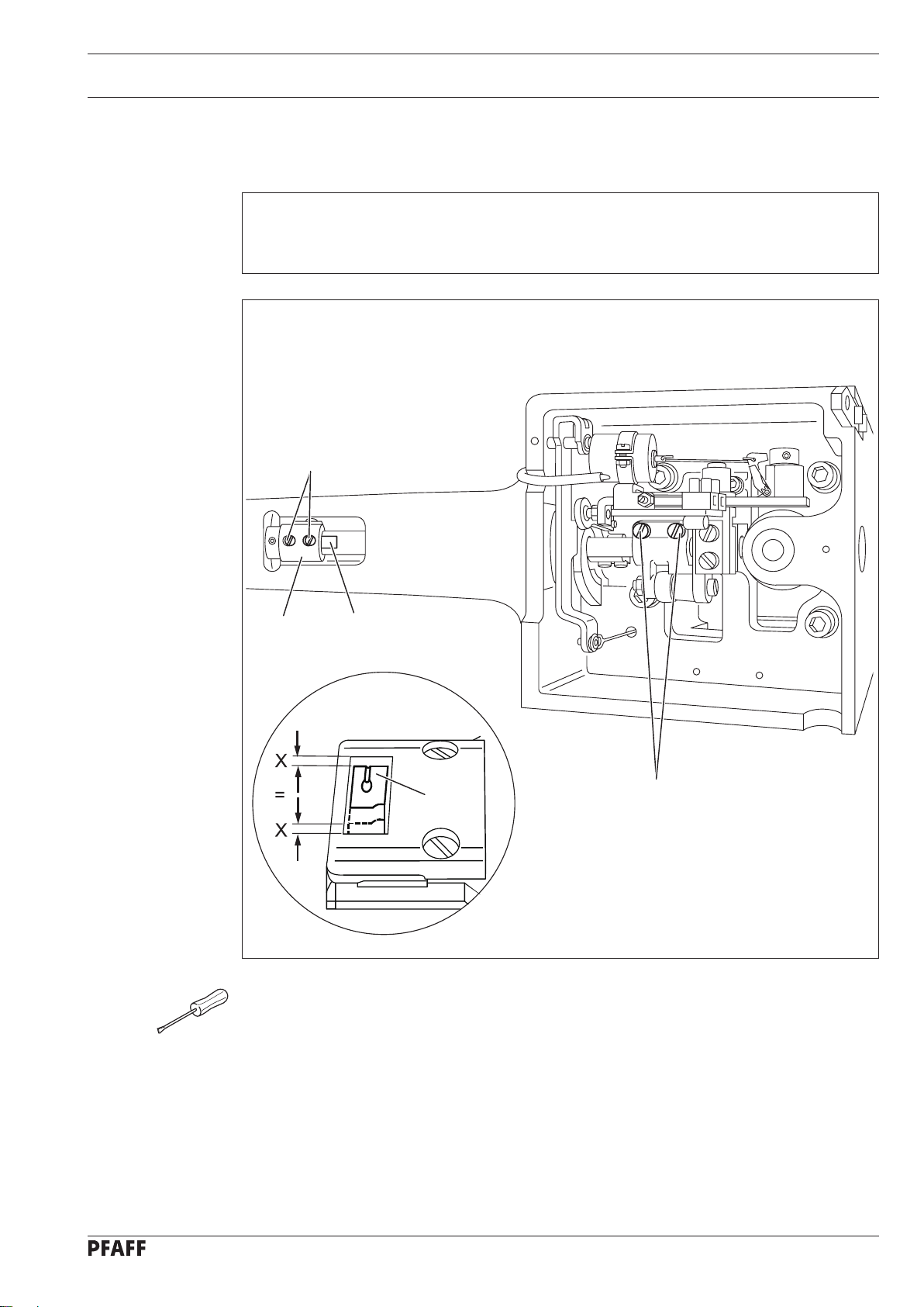
13.04.04 Centering the needle in the needle hole................................................................................ 9
13.04.05 Pre-adjusting the needle height ........................................................................................... 10
13.04.06 Driving motion of the top and bottom feed dogs................................................................. 11
13.04.07 Lifting motion of the bottom feed dog (only on machines with lifting phase – P-version).... 12
13.04.08 Needle rise, hook-to-needle clearance and needle height ................................................... 13
13.04.09 Vibrating presser lift ............................................................................................................. 14
13.04.10 Vibrating presser feeding motion......................................................................................... 15
13.04.11 Needle thread tension release............................................................................................. 16
13.04.12 Thread check spring ............................................................................................................. 17
13.04.13 Bobbin winder...................................................................................................................... 18
13.04.14 Regulating the pressure on the presser foot ....................................................................... 19
13.05 Adjusting the thread trimmer -900/52.................................................................................. 20
13.05.01 Preadjusting the control cam ............................................................................................... 20
13.05.02 Tripping lever height............................................................................................................. 21
13.05.03 Control pin ........................................................................................................................... 22
13.05.04 Engaging solenoid................................................................................................................ 23
13.05.05 Control pin height ................................................................................................................ 24
13.05.06 Front position of thread catcher ........................................................................................... 25
13.05.07 Lateral position of thread catcher ........................................................................................ 26
13.05.08 Control cam (final adjustment)............................................................................................. 27
13.05.09 Knife..................................................................................................................................... 28
13.05.10 Needle thread tension release............................................................................................. 29
13.05.11 Cutting test................................................................................................................................30

Index
Contents ..................................................................................Page
13.06 Parameter settings (only on machines with Quick-EcoDrive and control unit P40ED) ......... 31
13.06.01 Parameter list ....................................................................................................................... 31
14 Circuit diagrams ................................................................................................................. 32

Adjustment
5
13 Adjustment
Please observe all notes from Chapter 1 Safety of the instruction manual!
In particular care must be taken to see that all protective devices are refitted
properly after adjustment, see Chapter 1.06 Danger warnings of the instruction
manual!
If not otherwise stated, the machine must be disconnected from the electrical
power supply. Danger of injury due to unintentional starting of the machine!
13.01 Notes on adjustment
All following adjustments are based on a fully assembled machine and may only be carried
out by expert staff trained for this purpose.
Machine covers, which have to be removed and replaced to carry out checks and adjust-
ments, are not mentioned in the text.
The order of the following chapters corresponds to the most logical work sequence for
machines which have to be completely adjusted. If only specific individual work steps are
carried out, both the preceding and following chapters must be observed.
Screws, nuts indicated in brackets ( ) are fastenings for machine parts, which must be
loosened before adjustment and tightened again afterwards.
13.02 Tools, gauges and other accessories for adjusting
Screwdrivers with blade width from 2 to 10 mm
Spanners (wrenches) with jaw width from 7 to 14 mm
Allan keys from 2 to 6 mm
Metal rule (part No. 08-880 218-00)
Needle-rise gauge (part No. 61-111 600-01)
Gauge, (top feed stroke 7 mm) (Part No. 61-111 633-61)
Screw clamp (part No. 61-111 600-35)
13.03 Abbreviations
t.d.c. = top dead centre
b.d.c. = bottom dead centre
13.04 Explanation of the symbols
In this adjustment manual, symbols emphasize operations to be carried out or important in-
formation. The symbols used have the following meaning:
Note, information
Service, repair, adjustment, maintenance
(work to be carried out by qualified staff only)
●
●
●
●
●
●
●

Adjustment
6
13.01 Adjusting the basic machine
13.04.01 Lateral positioning of the feed dog
Requirement
The clearances from the left and right of the bottom feed dog 1 to the needle plate cutout
must be the the same size.
Move the bottom feed dog 1 (screws 2) in accordance with the requirement.●
Fig. 13 - 01
2
1

Adjustment
7
13.04.02 Lengthwise positioning of the feed dog
Requirement
With the stitch length set at its longest the clearances behind and in front of the bottom
feed dog 4 to the needle plate cutout must be the same.
Set the longest stitch length.
Move the clamp piece 1 (screws 2) as far to the left as possible on the clamp surface 3
of the rock shaft. The left screw must still be on the clamp surface.
Position feed dog 4 (screws 5) according to requirement.
●
●
●
Fig. 13 - 02
3
1
2
5
4

Adjustment
8
13.04.03 Height of the bottom feed dog (only on machines with lifting phase – P-version)
Requirement
When the stitch length is set at "0", in its highest position the bottom feed dog 4 should
be 0.8 - 1.1 mm above the top edge of the needle plate.
Set the stitch length at "0".
Adjust eccentric 1 and 2 (screws 3) in accordance with the requirement.
The bottom feed dog 4 should not touch cloth plate 5.
●
●
Fig. 13 - 03
2
3
4
1
5
3
4

Adjustment
9
13.04.04 Centering the needle in the needle hole
Requirement
With the stitch length set at "0"the needle must enter the needle hole exactly in the middle.
Unscrew the vibrating presser foot 1 and the presser foot 2.
Set the stitch length at "0"and bring the needle to its tdc.
Insert a new needle. Loosen screws 3, 4, 5 and 6.
Bring the needle to a position directly over the bottom feed dog by turning the
handwheel.
Move the needle bar frame 7 in accordance with the requirement.
Tighten screws 3, 4 and 5.
Position stop 8 so that it is touching the needle bar frame 7 and tighten screw 6.
The needle bar frame 7 in guide 9 and the vibrating presser drive shaft must
move freely.
●
●
●
●
●
●
●
Fig. 13 - 04
2
7
4
1
5
3
6
8
9
5

Adjustment
10
13.04.05 Pre-adjusting the needle height
Requirement
With the needle bar at its bdc the distance between the needle bar and the needle plate
must be 15 mm.
Move the needle bar 1 (screw 2) in accordance with the requirement without twisting it.●
Fig. 13 - 05
2
1

Adjustment
11
13.04.06 Driving motion of the top and bottom feed dogs
Requirement
With the longest stitch length set and the needle bar at its bdc the top and bottom feed
dogs should not move when the reverse feed lever is activated.
Set the longest stitch length.
Loosen screw 1 far enough so that the feed driving eccentric 2 can be turned on the
shaft with some difficulty.
Bring the needle to its bdc.
While keeping this position, move the feed driving eccentric 2 to the top and then move
it slightly so that the requirement is fulfilled when the reverse feed lever is activated.
Tighten screws 1.
●
●
●
●
●
Fig. 13 - 06
1
2

Adjustment
12
13.04.07 Lifting motion of the bottom feed dog
(only on machines with lifting phase – P-version)
Requirement
With the needle bar positioned at b.d.c., the bottom feed doc should be in the t.d.c.
position.
With the maximum stitch length set, when the balance wheel is turned the bottom
feed dog should reach the needle plate surface at the same time as the needle point.
1.
2.
Adjust eccentric 1 (screws 2) in accordance with the requirements.●
Fig. 13 - 07
1
2

Adjustment
13
13.04.08 Needle rise, hook-to-needle clearance and needle height
Requirement
With the stitch length set at "3" (1.8 mm after the bdc of the needle bar) the following
must be correct:
The hook point must be opposite the middle of the needle and the distance to the needle
must be 0.05 - 0.1 mm.
The top edge of the needle eye must be 0.8 mm from the hook point.
1.
2.
Set the stitch length at "3" and loosen screws 1 and 2 (screw 2 is on the back of the
machine).
Set the needle bar at b.d.c. and place the 1.8 mm thick feeler gauge with its cutout close
under the lower needle bar bearing.
Remove the measuring plate and turn the handwheel in its direction of rotation until the
screw clamp is touching the needle bar bearing.
Move the hook on the hook shaft in accordance with requirement 1.
Rotate the hook in accordance with requirement 2 (adjust needle height if necessary).
Bring the hook shaft bearing 3 to rest on the hook and tighten screw 2.
Taking care to ensure that the bevel gear 4 is resting on the bearing 5, tighten screws 1.
On machines with a thread trimmer the adjustment of the axial play on the
hook shaft and the adjustment of the hook shaft bearing 3 are not necessary.
●
●
●
●
●
●
●
Fig. 13 - 08
12
13
5
4

Adjustment
14
13.04.09 Vibrating presser lift
Requirement
With the vibrating presser lift at maximum and the stitch length set at "0", presser foot 1
and vibrating presser foot 2 must lift 7.0 mm from the needle plate when the handwheel
is rotated.
Set the vibrating presser lift at maximum and the stitch length at "0".
Allow the presser foot 1 to rest on the needle plate.
Turn the handwheel in its direction of rotation until the vibrating presser foot 2 has
reached its highest point.
Turn crank 3 (screws 4) in accordance with the requirement.
Carry out a check.
●
●
●
●
●
Fig. 13 - 9
1
2
3
4

Adjustment
15
13.04.10 Vibrating presser feeding motion
Requirement
With the presser foot 3 resting on the needle plate the vibrating presser 6 and the needle
point must both reach the needle plate at the same time with the vibrating presser stroke
at maximum.
Loosen nut 1.
Slide bolt 2 upwards in the elongated hole and tighten nut 1.
Allow the presser foot 3 to rest on the needle plate.
Loosen screws 4 enough so that the feed lifting eccentric 5 can be rotated with
difficulty.
Rotate the lifting eccentric 5 in accordance with the requirement.
Tighten screws 4.
Carry out a check.
●
●
●
●
●
●
●
Fig. 13 - 10
12
3
4
6
5

Adjustment
16
13.04.11 Needle thread tension release
Requirement
With the presser foot lifted, the two tension disks must be at least 0.5 mm apart.
Raise the presser foot using the hand lever.
Align the compression plate 1 behind the tension bearing board 2 in accordance with the
requirement.
When the tension is correct the release pin must not be under pressure.
●
●
Fig. 13 - 11
The distance of 0.5 mm is the minimum clearance. The clearance can range up
to more than 1 mm with thick threads.
2
1
3
0,5 mm

Adjustment
17
13.04.12 Thread check spring
Adjust stop 1 (screw 2) according to Requirement.
To adjust the pressure of the spring, turn screw 3 (screw 4).
●
●
The length of the spring movement can vary a little upwards or downwards due
to changes in the sewing parameters.
Requirement
The movement of the thread check spring must be finished when the needle point enters
the material (= approx. 7 mm spring movement).
Fig. 13 - 12
2
1
3
4

Adjustment
18
13.04.13 Bobbin winder
Requirement
With the bobbin winder engaged the winder spindle must be driven reliably. With the bob-
bin winder disengaged, however, the friction wheel 5 must not touch the drive wheel 1.
The bobbin winder must stop automatically when the thread wound on the bobbin has
reached a point approx. 1 mm below the bobbin rim.
1.
2.
Adjust the drive wheel 1 (screws 2) in accordance with requirement 1.
Place a bobbin on the winder spindle, thread the bobbin and switch on the bobbin
winder.
Shift the regulating pin 3 (screws 4) in accordance with requirement 2.
●
●
●
Fig. 13 - 13
2
3
1
2
4
5

Adjustment
19
13.04.14 Regulating the pressure on the presser foot
Requirement
The material must be fed perfectly even at top sewing speed. There must not be any
pressure marks on the material.
Turn screw 1 in accordance with the requirement.●
Fig. 13 - 14
4

Adjustment
20
13.05 Adjusting the thread trimmer -900/52
Requirement
With the take-up lever at its bdc, projection 4 on the control cam 2 must be directly un-
derneath the cam follower 5.
Loosen screws 1 through the hole in the machine housing.
Set the take-up lever at b.d.c.
Turn control cam 2 according to Requirement.
Move control cam 2 down against bearing 3 and tighten the accessible screw 1.
Make the second screw 1 accessible and tighten it also.
●
●
●
●
●
Fig. 13 - 15
2
1
2
4
3
5
13.05.01 Preadjusting the control cam
Please note that on all machines with thread trimmer -900/52 the stitch length
must be limited to 5.5 mm!
Other manuals for 335
5
Table of contents
Other Pfaff Sewing Machine manuals

Pfaff
Pfaff 1181 User manual

Pfaff
Pfaff creative 2170 Guide

Pfaff
Pfaff varimatic 6085 User manual

Pfaff
Pfaff dorina 72 User manual

Pfaff
Pfaff perfomance 2058 User manual

Pfaff
Pfaff hobby 1122 User manual

Pfaff
Pfaff 918 User manual

Pfaff
Pfaff 3734 -12 User manual

Pfaff
Pfaff 76 User manual

Pfaff
Pfaff 1445 User manual

Pfaff
Pfaff FREESTYLE 1527 User manual

Pfaff
Pfaff Creative Vision User manual

Pfaff
Pfaff CREATIVE 4.0 - User manual

Pfaff
Pfaff EXPRESSION 2014 User manual

Pfaff
Pfaff expression 2034 User manual

Pfaff
Pfaff 571 Guide

Pfaff
Pfaff 418 Series User manual

Pfaff
Pfaff 1181 User manual

Pfaff
Pfaff 28 User manual

Pfaff
Pfaff 900/56 User manual