Pfaff 337 Guide

ADJUSTMENT MANUAL
296-12-19 318/002
Adjustment manual engl. 11.15
This adjustment manual applies to machines
from the serial number 7 262 535 and
software version 0435/002 onwards.
337

Reprinting, reproduction and/or translation of PFAFF adjustment manuals
(including parts thereof) is only permitted with our prior agreement and
citation of the source.
PFAFF Industriesysteme
und Maschinen GmbH
Hans-Geiger-Str. 12 - IG Nord
D-67661 Kaiserslautern

Table of Contents
Contents ..................................................................................Page
13 Adjustment ........................................................................................................................... 5
13.01 Tools, gauges and other accessories .................................................................................... 5
13.02 Abbreviations ......................................................................................................................... 5
13.03 Explanation of symbols.......................................................................................................... 5
13.04 Adjusting basic machine ........................................................................................................ 6
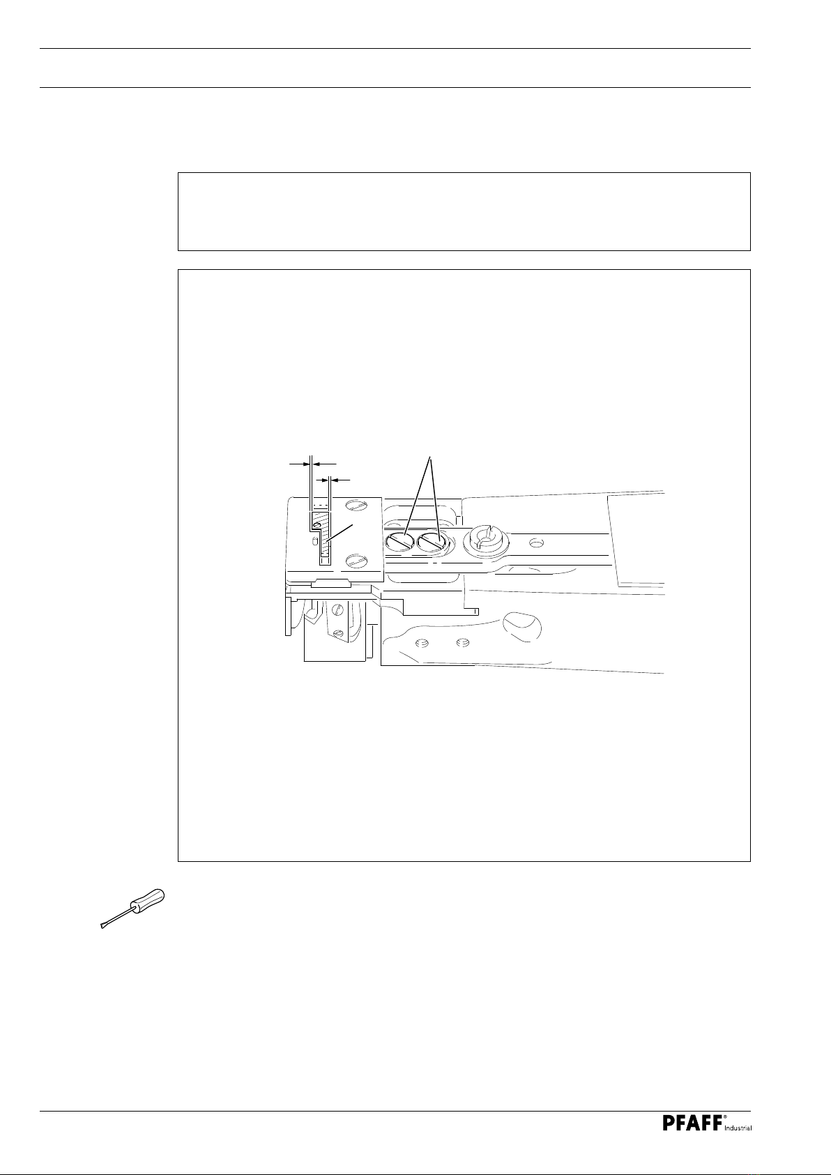
13.04.01 Feed dog position crossways to sewing direction................................................................. 6
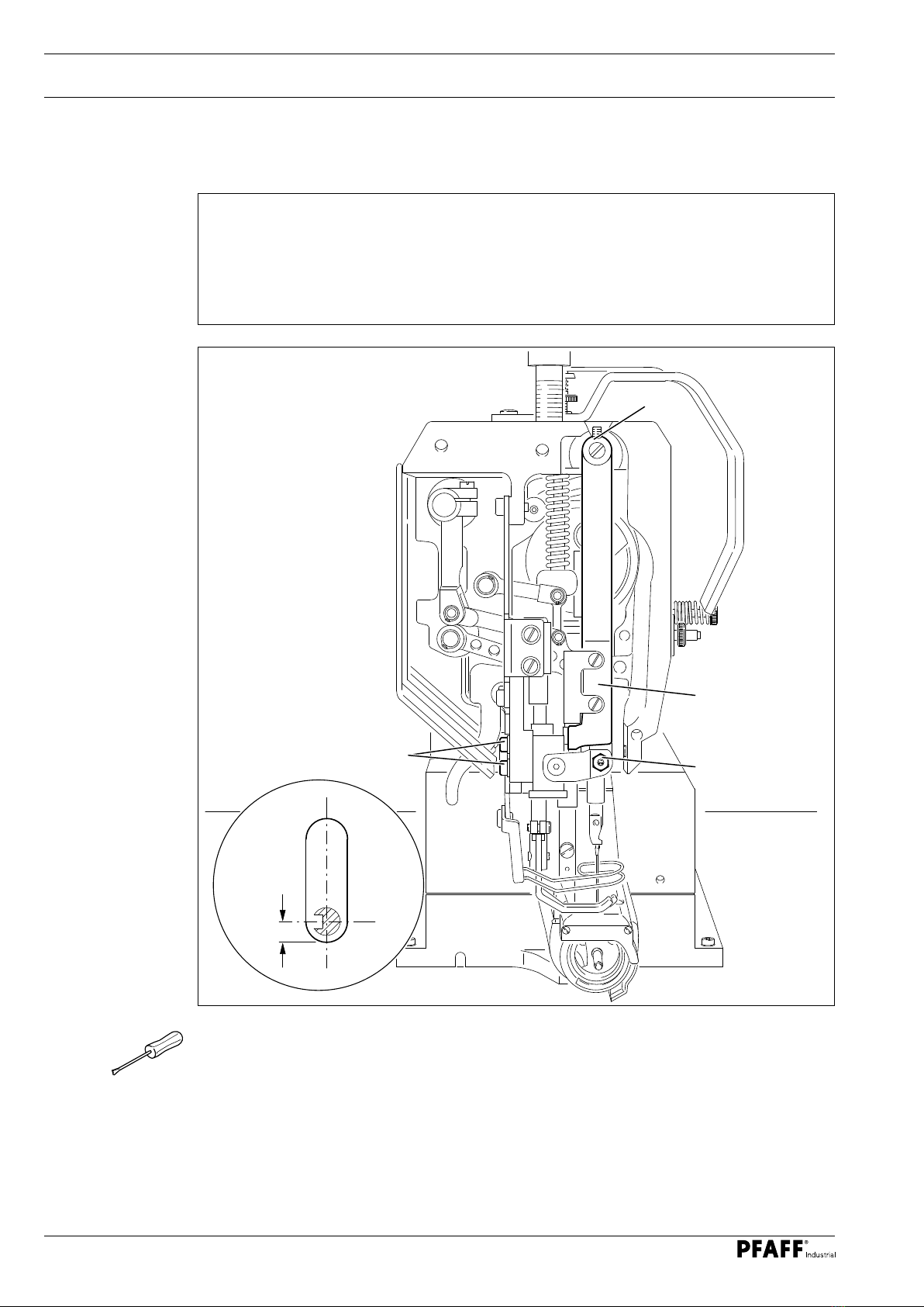
13.04.02 Feed dog position in sewing direction ................................................................................... 7
13.04.03 Needle position to needle hole .............................................................................................. 8
13.04.04 Needle height (pre-calibrating) ............................................................................................... 9
13.04.05 Bottom and top feed sliding movement .............................................................................. 10
13.04.06 Hook-to-needle clearance, needle bar rise, needle height and needle guard ...................... 11
13.04.07 Top feed lift.......................................................................................................................... 12
13.04.08 Top feed stroke movement ................................................................................................. 13
13.04.09 Top feed pendulum.............................................................................................................. 14
13.04.10 Needle thread tension release............................................................................................. 15
13.04.11 Thread check spring............................................................................................................. 16
13.04.12 Bobbin winder...................................................................................................................... 17
13.04.13 Presser foot pressure .......................................................................................................... 18
13.05 Adjusting thread trimmer -900/51 .................................................................................... 19
13.05.01 Control cam ( pre-calibrating ) .............................................................................................. 19
13.05.02 Tripping lever height ............................................................................................................ 20
13.05.03 Feed regulator pin................................................................................................................ 21
13.05.04 Engaging solenoid................................................................................................................ 22

Table of Contents
Contents ..................................................................................Page
13.05.05 Feed regulator pin height..................................................................................................... 23
13.05.06 Front turning point of thread catcher ................................................................................... 24
13.05.07 Aligning thread catcher laterally........................................................................................... 25
13.05.08 Control cam (recalibrating) ................................................................................................... 26
13.05.09 Knife..................................................................................................................................... 27
13.05.10 Test cut................................................................................................................................ 28
13.06 Parameter settings ............................................................................................................. 29
13.07 Internet update of control P40 CD ...................................................................................... 29
14 Circuit Diagrams ............................................................................................................... 30

Adjustment
5
13 Adjustment
Observe and comply with all instructions in the operating manual's chapter
1 Safety! In particular make sure that all safety covers are installed again
correctly after making adjustments, see chapter 1.06 Operating manual
hazard information!
Unless otherwise stated, the machine must be disconnected from the power
supply before all adjustment work!
Risk of injury due to accidental machine start-up!
Notes on adjustment
All adjustments in this manual are based on a fully assembled machine and may only be
carried out by technical staff trained for this purpose. Machine covers, which have to be
removed and replaced to carry out checks and adjustments, are not mentioned in the text.
The order of the following chapters corresponds to the most logical work sequence for
machines that have to be completely adjusted. Both the preceding and following chapters
must be observed if only specific individual work steps are carried out. Screws and nuts
indicated in brackets () are fastenings for machine parts, which must be loosened before any
adjustment and tightened again afterwards.
13.01 Tools, gauges and other accessories
O1 set of screwdrivers with blade widths from 2 to 10 mm
O1 set of wrenches with jaw widths from 7 to 14 mm
O1 set of Allen keys from 2 to 6 mm
O1 metal ruler (order no. 08-880 218-00)
ONeedle rise gauge (order no. 61-111 600-01)
OScrew clamp (order no. 61-111 600-35)
OTop feed lift gauge ( order no. 61-111 633-61)
13.02 Abbreviations
t.d.c. = top dead centre
b.d.c. = bottom dead centre
13.03 Explanation of symbols
Activities to be performed or important information in this adjustment manual are
emphasised by symbols. The symbols used have the following meaning:
Note, information
Maintenance, repairs, adjustment, service work
(only to be carried out by technical staff)

Adjustment
6
Fig. 13 - 01
13.04 Adjusting basic machine
13.04.01 Feed dog position crossways to sewing direction
Rule
The bottom transporter should have the same clearance on the right and left in the
needle plate recess.
OAdjust the bottom transporter 1 (screws 2) according to the rule.
1
2
X
X

Adjustment
7
13.04.02 Feed dog position in sewing direction
Rule
The bottom transporter 4 should have the same clearance at the front and back in the
needle plate recess in forward and reverse feed at the maximum stitch length setting.
OSet the maximum stitch length.
OPlace the clamping piece 1 (screws 2) as far as possible to the left on the clamping
surface 3 of the rock shaft. The left-hand screw must still be on the clamping surface.
OAdjust the bottom transporter 4 (screws 5) according to the rule.
Fig. 13 - 02
3
1
2
5
4
X
X

Adjustment
8
13.04.03 Needle position to needle hole
Fig. 13 - 03
Rule
1. In the sewing direction, a clearance of approximately 0.7 mm should remain between
the needle midpoint and the front inside edge of the needle hole.
2. The needle should be at the centre of the needle hole when diagonal to the sewing
direction.
OMove the needle directly over the needle hole by turning the handwheel.
OAdjust the needle bar frame 1 (nut 2 with lock nut) according to rule 1.
OMove the needle bar frame 1 (screws 3 and 4) according to rule 2.
2
4
1
3
0.7 mm

Adjustment
9
Fig. 13 - 04
13.04.04 Needle height (pre-calibrating)
Rule
When the needle bar is in b.d.c., the clearance between the needle bar and needle plate
should be 15 mm.
OAdjust the needle bar 1 ( screw 2 ) without twisting according to the rule.
1
2

Adjustment
10
13.04.05 Bottom and top feed sliding movement
OSet the maximum stitch length.
OLoosen the screws 1 only to such an extent that the eccentric 2 is difficult to turn on the
shaft.
OMove the needle bar to b.d.c.
OTurn the eccentric 2 according to the rule.
OTighten the screws 1.
Fig. 13 - 05
1
2
Rule
When, approaching from above, the needle bar's lower edge is located 33 mm above the
needle plate's upper edge, the top and bottom transporter should not move when the
reverse-feed lever is activated.
33 mm

Adjustment
11
13.04.06 Hook-to-needle clearance, needle bar rise, needle height and needle guard
Rule
When the needle bar rise is positioned 1.8 mm after b.d.c. of the needle bar and with
maximum stitch length regulation,
1. the hook point should be at the needle midpoint and have a clearance of 0.05 to
0.1 mm to the needle.
2. the upper edge of the eye of the needle should be 0.8 mm under the hook point.
OSet the maximum stitch length.
OLoosen screws 1 and 2 (screw 2 is located on the back of the machine).
OMove the needle bar to b.d.c. and slide the 1.8 mm thick feeler gauge with its cutout
tightly under the lower needle bar bearing. Move the screw clamp so that it touches the
feeler gauge and tighten it.
ORemove the feeler gauge and turn the handwheel in the direction of rotation until the
screw clamp rests on the needle bar bearing.
OAdjust the hook on the hook shaft according to rule 1
OTurn the hook according to rule 2 (readjust the needle height if necessary), see chapter
13.04.04 Needle height (pre-calibrating).
OMove the hook shaft bearing 3 until it abuts the hook and tighten the screw 2.
OMove the bevel gear 4 until it abuts the bearing 5 and tighten the screws 1.
The setting of the end play of the hook shaft and hook shaft bearing 3 is
omitted in machines with thread trimmer -900/51.
Fig. 13 - 06
12
13
5
4
0.05 - 0.1 mm
0.8 mm

Adjustment
12
Fig. 13 - 07
13.04.07 Top feed lift
Rule
When lever 1 is in the centre of its slotted lever, presser foot 3 and top feed foot 4
should be at the same height above the needle plate.
OSet the stitch length to "0".
OSet lever 1 (screw 2) into the centre of its slotted lever.
OFit the presser foot 3.
OTurn handwheel in the direction of rotation until top feed foot 4 reaches its upper turning
point.
OTurn the crank 5 (screw 6) according to the rule.
1
2
6
5
4
3
X

Adjustment
13
Fig. 13 - 08
13.04.08 Top feed stroke movement
Rule
When, approaching from above, the needle bar's lower edge is located 33 mm above the
needle plate's upper edge, the top transporter should not move when the slotted lever 3
moves up and down.
OLoosen the screws 1 until the eccentric 2 is difficult to turn on its shaft.
OMove the needle bar into the appropriate position.
OTurn the eccentric 2 according to the rule.
OTighten the screws 1.
1
2
3
33 mm

Adjustment
14
Fig. 13 - 09
13.04.09 Top feed pendulum
Rule
When the stitch length is set to "0"and the machine has a maximum gathering setting,
the presser rod 4 should be in the centre between needle bar guide and presser bar.
OSlide the connecting rod 1 (screw 2) in its slotted lever 3 until you feel it reach the upper
stop.
OSet the stitch length "0"and switch it to maximum gathering setting by operating the
pedal.
OAdjust the presser rod 4 (screw 5) according to the rule.
12
35
4

Adjustment
15
13.04.10 Needle thread tension release
Rule
When the presser foot is raised, both tension discs should be at least 0.5 mm apart.
ORaise the presser foot with the hand lever.
OAlign the pressure plate 1 behind the tension mounting plate 2 according to the rule.
The release pin 3 must not be loaded with effective tension.
Fig. 13 - 10
The clearance of 0.5 mm is the minimum size and may be over 1 mm with
thick types of yarn.
2
1
3
0.5 mm

Adjustment
16
Fig. 13 - 11
2
1
3
4
13.04.11 Thread check spring
OAdjust the stop 1 ( screw 2 ) according to the rule.
OTurn the screw 3 ( screw 4 ) to set the spring tension
The length of the thread check spring deflection may deviate slightly upwards
or downwards for reasons relating to the sewing technology.
Rule
The movement of the thread check spring 5 should be finished when the needle point
punctures the material (spring deflection = approx. 7 mm).
5
7 mm

Adjustment
17
1
2
5
Fig. 13 - 12
13.04.12 Bobbin winder
Rule
1. When the bobbin winder is switched on, the bobbin winder spindle should be moved
easily; when the bobbin winder is switched off, the friction wheel 5 must not touch
the drive wheel 1.
2. The bobbin winder should switch off automatically when the fill amount is still around
1 mm from the edge of the bobbin.
OAdjust the drive wheel 1 (screws 2) according to rule1.
OAdjust the bolt 3 (screws 4) according to rule 2.
3
4
1 mm

Adjustment
18
Fig. 13 - 13
13.04.13 Presser foot pressure
Rule
The material should be transported properly even at top sewing speed.
No pressure marks should appear on the material.
OTurn the screw 1 according to the rule.
1

Adjustment
19
Fig. 13 - 14
13.05 Adjusting thread trimmer -900/51
13.05.01 Control cam ( pre-calibrating )
Rule
When the thread lever is in b.d.c. the groove 4 of the control cam 2 should stand vertical
under the feed regulator pin 5.
OLoosen the screws 1 through the hole in the machine housing.
OMove the thread lever to b.d.c.
OTurn the control cam 2 according to the rule.
OMove the control cam 2 down so that it touches the bearing 3 and tighten the accessible
screw 1.
OMake the second screw 1 accessible and tighten it.
2
1
2
4
3
5

Adjustment
20
13.05.02 Tripping lever height
Rule
When the needle bar is in b.d.c., there should be a clearance of 1.0 mm between the trip-
ping lever 3 and the control cam 4.
OMove the needle bar to b.d.c.
OAdjust the carrier 1 (screws 2) of the tripping lever 3 in the elongated hole according to
the rule.
Fig. 1 3- 15
1
3
2
4
1 mm
Other manuals for 337
1
Table of contents
Other Pfaff Sewing Machine manuals

Pfaff
Pfaff 3574-2/02 User manual

Pfaff
Pfaff 3538-20/02 Guide

Pfaff
Pfaff synchrotronic 1229 User manual

Pfaff
Pfaff 51 User manual

Pfaff
Pfaff Hobby 521 User manual

Pfaff
Pfaff 3538-30/02 User manual

Pfaff
Pfaff tipmatic tiptronic 1151 User manual

Pfaff
Pfaff 421E1 User manual

Pfaff
Pfaff 487 User manual

Pfaff
Pfaff 1181 User manual

Pfaff
Pfaff hobby 4240 User manual

Pfaff
Pfaff HOBBYMATIC 800 User manual

Pfaff
Pfaff 16 User manual

Pfaff
Pfaff 2481-980/30 PLUSLINE Guide

Pfaff
Pfaff CREATIVE 4.0 - User manual

Pfaff
Pfaff POWERLINE 3741 User manual

Pfaff
Pfaff 5483 Series Guide

Pfaff
Pfaff hobbylock 4762 User manual

Pfaff
Pfaff Hobby 301 User manual

Pfaff
Pfaff 1070s User manual